

Parts Sheet - You are now at the Down-Load Site for Tol-O - Tolomatic
Parts Sheet - You are now at the Down-Load Site for Tol-O - Tolomatic
Parts Sheet - You are now at the Down-Load Site for Tol-O - Tolomatic

Create successful ePaper yourself
Turn your PDF publications into a flip-book with our unique Google optimized e-Paper software.
<strong>Parts</strong> <strong>Sheet</strong> #3600-4130_11_B3S20ps B3S20, M3S20 Options – 11<br />
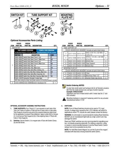
SWITCH KIT<br />
1 2<br />
3<br />
4<br />
TUBE SUPPORT KIT<br />
Optional Accessories <strong>Parts</strong> Listing<br />
Item<br />
B3S20<br />
Part No.<br />
M3S20<br />
Part No. Description QTY.<br />
SWITCH KIT<br />
Part Number Ordering Config. Code Ordering<br />
No Mounting Hardw<strong>are</strong> or FE conn. included Mounting Hardw<strong>are</strong> & FE conn. included<br />
Part NO. Description Code<br />
3600-9084 Switch Only, Reed, Form C, 5m BT<br />
3600-9085 Switch Only, Reed, Form C, Male Conn. BM<br />
3600-9082 Switch Only, Reed, Form A, 5m RT<br />
1<br />
3600-9083 Switch Only, Reed, Form A, Male Conn. RM<br />
3600-9086 Switch Only, Triac, 5m CT<br />
3600-9087 Switch Only, Triac, Male Conn. CM<br />
3600-9090 Switch Only, Hall-effect, Sinking, 5m KT<br />
3600-9091 Switch Only, Hall-effect, Sinking, Male Conn. KM<br />
3600-9088 Switch Only, Hall-effect, Sourcing, 5m TT<br />
3600-9089 Switch Only, Hall-effect, Sourcing, Male Conn. TM<br />
2503-1025 Connector (Female) 5 meter lead<br />
NOTE: When ordered by Config. Code Female connector & all mounting hardw<strong>are</strong> is included<br />
2 3420-9999 3420-9999 Switch Hardw<strong>are</strong> Kit 1<br />
5<br />
6<br />
7<br />
MOUNTING<br />
PLATE KIT<br />
8<br />
9<br />
10<br />
Item<br />
B3S20<br />
Part No.<br />
M3S20<br />
Part No. Description QTY.<br />
TUBE SUPPORT KIT<br />
3420-9006 4420-9006 KIT Includes all parts listed below<br />
3 2317-1015 4415-1011<br />
SHCS, 5/16-18 x .63/ M8 x<br />
1.25 x 12<br />
4<br />
4 3415-1046 4415-1014<br />
SFHCS, 1/4-20 x .44/ M6<br />
x 1 x 10<br />
4<br />
5 3420-1013 4420-1013 B3S20 Nut 4<br />
6 3420-1044 3420-1044 Tube Support 2<br />
7 3420-1013 4420-1013 B3S20 Nut 4<br />
Mounting Pl<strong>at</strong>e Kit<br />
3420-9056 4420-9030 KIT Includes all parts listed below<br />
8 3420-1013 4420-1013 T-Nut 2<br />
9 3420-1232 3420-1232 Mounting Pl<strong>at</strong>e 1/2" 1<br />
10 2307-1018 4415-1011 Socket Head Cap Screw 2<br />
Switch Ordering NOTES:<br />
To order field retrofit switch and hardw<strong>are</strong> kits <strong>for</strong> all <strong>Tol</strong>om<strong>at</strong>ic actu<strong>at</strong>ors:<br />
SW (Then <strong>the</strong> model and bore size, and type of switch required)<br />
Example: SWB3S20RT<br />
(Hardw<strong>are</strong> and Form A Reed switch with 5 meter lead <strong>for</strong> 2" size<br />
B3S actu<strong>at</strong>or)<br />
Mounting hardw<strong>are</strong> is required if replacing switch <strong>for</strong> any actu<strong>at</strong>or<br />
manufactured be<strong>for</strong>e 7/1/97<br />
OPTIONAL ACCESSORY ASSEMBLY INSTRUCTIONS<br />
1. TUBE SUPPORTS. Four T-Nuts (5, 7) <strong>are</strong> required on each side of <strong>the</strong><br />
Tube, two T-Nuts on bottom of Tube and two in lower slots on tube sides.<br />
Tube Supports should be secured <strong>at</strong> <strong>the</strong> required distances determined<br />
<strong>for</strong> <strong>the</strong> applic<strong>at</strong>ion to prevent Tube deflection. Apply Loctite #242 to Screws<br />
(3, 4) and secure Tube Supports (6) to Tube aligning holes in T-Nuts with<br />
holes in Tube Supports.<br />
2. Switches. Secure Switch (1) to magnet side of Tube with Switch Clamp<br />
(2) and Set Screw.<br />
3. SWITCHES<br />
NOTE: Form A Reed Switches should not be used in TTL logic<br />
circuits. A voltage drop caused by <strong>the</strong> L.E.D. indic<strong>at</strong>or will result.For<br />
applic<strong>at</strong>ions where TTL circuits <strong>are</strong> used, please contact <strong>the</strong> factory.<br />
WARNING: An ohmmeter is recommended <strong>for</strong> testing Reed Switches.<br />
NEVER use an incandescent light bulb as a high current rush may<br />
damage <strong>the</strong> switch.<br />
Reed and TRIAC switches <strong>are</strong> only recommended <strong>for</strong> signalling position,<br />
not directly powering solenoids. For shifting a solenoid, a relay<br />
or resistor is recommended between it and <strong>the</strong> Reed Switch. Switch<br />
r<strong>at</strong>ings must not be exceeded <strong>at</strong> any time.<br />
NOTE: For Hall Effect Switch Magnet, be sure <strong>the</strong> S pole of <strong>the</strong> magnet<br />
(indic<strong>at</strong>ed with black dot) is facing toward <strong>the</strong> switch (down).<br />
<strong>Tol</strong>om<strong>at</strong>ic • URL: http://www.tolom<strong>at</strong>ic.com • Email: help@tolom<strong>at</strong>ic.com • Fax: (763) 478-8080 • <strong>Tol</strong>l Free: 1-800-328-2174


