

BC3 ReCiRCulating Ball BeaRing Rodless CylindeR
BC3 ReCiRCulating Ball BeaRing Rodless CylindeR
BC3 ReCiRCulating Ball BeaRing Rodless CylindeR

Create successful ePaper yourself
Turn your PDF publications into a flip-book with our unique Google optimized e-Paper software.
abt MXP BC2 <strong>BC3</strong> BC4 LS MG CC PB ENGR<br />
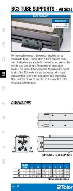
<strong>BC3</strong> TUBE SUPPORTS - All Sizes<br />
For intermediate support, tube support brackets can be<br />
mounted to the <strong>BC3</strong> model. Made of black-anodized aluminum,<br />
the brackets are attached to the bottom and sides of the<br />
cylinder tube with rail nuts. The number of tube support<br />
brackets required and their placement depends on the overall<br />
length of the <strong>BC3</strong> model and the load weight being moved<br />
and supported. Refer to the tube support data chart below.<br />
Note: Switches cannot be mounted on the same face of the<br />
actuator as tube supports.<br />
DIMENSIONS<br />
TUBE SUPPORT<br />
ORDER CODE<br />
TS_<br />
(_ = Number ordered)<br />
OPTIONAL TUBE SUPPORT<br />
BORE<br />
SIZE A B C D E F G<br />
10 1.00 2.75 2.250 0.25 1.53 1.76 1.09 0.206<br />
15 1.50 3.75 3.000 0.38 1.97 2.19 1.16 0.266<br />
20 2.00 4.00 3.375 0.31 2.56 2.84 1.50 0.328<br />
Dimensions in inches<br />
PERFORMANCE<br />
LOAD WEIGHT (lbs.)<br />
2200<br />
2000<br />
1800<br />
1600<br />
1400<br />
1200<br />
1000<br />
C<br />
TUBE SUPPORT REQUIREMENTS<br />
800<br />
600<br />
400<br />
200<br />
A<br />
B<br />
Max Distance Between Supports (mm) “L”<br />
0<br />
76.2<br />
152.4<br />
228.6<br />
304.8<br />
381.0<br />
457.2<br />
533.4<br />
609.6<br />
685.8<br />
762.0<br />
838.2<br />
914.4<br />
<strong>BC3</strong>20:<br />
<strong>BC3</strong>15:<br />
<strong>BC3</strong>10:<br />
0<br />
0<br />
0 3 6 9 12 15 18 21 24 27 30 33 36<br />
Max Distance Between Supports (in.) “L”<br />
Weight<br />
F<br />
Ø G<br />
D<br />
Maximum Allowable Load<br />
L<br />
E<br />
3d cad available at<br />
www.tolomatic.com<br />
997.8<br />
907.2<br />
816.4<br />
725.8<br />
635.0<br />
544.3<br />
453.6<br />
362.9<br />
272.2<br />
181.4<br />
90.7<br />
LOAD WEIGHT (kgs.)<br />
BORE<br />
SIZE A B C D E F G<br />
M10 25 69.85 57.15 6.4 38.9 44.7 27.7 5.232<br />
M15 40 95.30 76.20 9.7 50.0 55.6 29.5 6.756<br />
M20 50 101.60 85.73 7.9 65.0 72.1 38.1 8.331<br />
Dimensions in millimeters<br />
<strong>BC3</strong> _12 1.800.328.2174


