

BC3 ReCiRCulating Ball BeaRing Rodless CylindeR
BC3 ReCiRCulating Ball BeaRing Rodless CylindeR
BC3 ReCiRCulating Ball BeaRing Rodless CylindeR

Create successful ePaper yourself
Turn your PDF publications into a flip-book with our unique Google optimized e-Paper software.
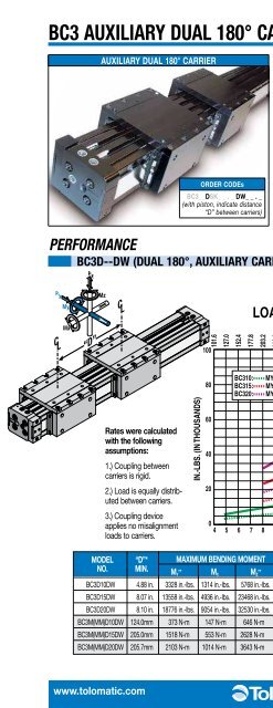
<strong>BC3</strong> AUXILIARY DUAL 180° CARRIER - All Sizes<br />
AUXILIARY DUAl 180° CARRIER<br />
AUXILIARY DUAL 180° CARRIER<br />
Rates were calculated<br />
with the following<br />
assumptions:<br />
1.) Coupling between<br />
carriers is rigid.<br />
2.) Load is equally distributed<br />
between carriers.<br />
3.) Coupling device<br />
applies no misalignment<br />
loads to carriers.<br />
ORDER CODEs<br />
<strong>BC3</strong>_ _DSK_ _ . _ DW_ _ . _<br />
(with piston, indicate distance<br />
“D” between carriers)<br />
IN.-LBS. (IN THOUSANDS)<br />
100<br />
80<br />
60<br />
40<br />
20<br />
0<br />
4<br />
The auxiliary dual 180° carrier option substantially increases<br />
load carrying capacity and bending moments. Auxiliary carriers<br />
can only be ordered with an internal piston. When ordering,<br />
determine the minimum distance required between carriers<br />
(dimension “D” in Auxiliary Dual 180° Carrier Bending<br />
Moments chart below). Determine your working stroke. Enter<br />
these into your configuration string. (Example<br />
Ordering<br />
Procedure<br />
<strong>BC3</strong>D15SK50.00DW10.00) The configurator will calculate<br />
the overall length of the actuator.<br />
NOTE: Breakaway pressure will increase when using<br />
auxiliary dual 180° carriers.<br />
PERFORMANCE<br />
<strong>BC3</strong>D--DW (DUAL 180°, AUXILIARY CARRIER) BENDING MOMENTS AND load<br />
LOAD vs. DISTANCE <strong>BC3</strong> SERIES<br />
“D” MILLIMETERS<br />
101.6<br />
127.0<br />
152.4<br />
177.8<br />
203.2<br />
228.6<br />
254.0<br />
279.0<br />
304.8<br />
330.2<br />
355.6<br />
381.0<br />
406.4<br />
431.8<br />
457.2<br />
482.6<br />
508.0<br />
533.4<br />
558.8<br />
584.2<br />
609.6<br />
635.0<br />
<strong>BC3</strong>10: MY Moment MZ Moment<br />
<strong>BC3</strong>15: MY Moment MZ Moment<br />
<strong>BC3</strong>20: MY Moment MZ Moment<br />
0<br />
5 6 7 8 9 10 11 12 13 14 15 16 17 18 19 20 21 22 23 24 25<br />
“D” INCHES<br />
Rates were calculated with the following assumptions:<br />
1.) Coupling between carriers is rigid. 2.) Load is equally distributed between carriers.<br />
3.) Coupling device applies no misalignment loads to carriers.<br />
MODEL “D”* MAXIMUM BENDING MOMENT MAXIMUM lOAD<br />
NO. MIN. M y<br />
** M x M z<br />
** F z F Y<br />
<strong>BC3</strong>D10DW 4.88 in. 3328 in.-lbs. 1314 in.-lbs. 5768 in.-lbs. 1364 lbs. 2364 lbs.<br />
<strong>BC3</strong>D15DW 8.07 in. 13558 in.-lbs. 4936 in.-lbs. 23468 in.-lbs. 3360 lbs. 5816 lbs.<br />
<strong>BC3</strong>D20DW 8.10 in. 18776 in.-lbs. 9054 in.-lbs. 32530 in.-lbs. 4636 lbs. 8032 lbs.<br />
<strong>BC3</strong>M(MM)D10DW 124.0mm 373 N-m 147 N-m 646 N-m 619 kgs. 1072 kgs.<br />
<strong>BC3</strong>M(MM)D15DW 205.0mm 1518 N-m 553 N-m 2628 N-m 1524 kgs. 2638 kgs.<br />
<strong>BC3</strong>M(MM)D20DW 205.7mm 2103 N-m 1014 N-m 3643 N-m 2103 kgs. 3643 kgs.<br />
11.30<br />
9.04<br />
6.78<br />
4.52<br />
2.26<br />
* D is distance between carriers.<br />
** loads calculated are at minimum “D”,<br />
for substantially higher My + Mz loads<br />
increase “D’ and refer to graph at left<br />
N-m (IN THOUSANDS)<br />
ENGR PB CC MG LS BC4 <strong>BC3</strong> BC2 MXP ABT<br />
www.tolomatic.com<br />
<strong>BC3</strong>_17


