

BC3 ReCiRCulating Ball BeaRing Rodless CylindeR
BC3 ReCiRCulating Ball BeaRing Rodless CylindeR
BC3 ReCiRCulating Ball BeaRing Rodless CylindeR

You also want an ePaper? Increase the reach of your titles
YUMPU automatically turns print PDFs into web optimized ePapers that Google loves.
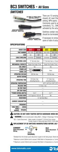
<strong>BC3</strong> SWITCHES - All Sizes<br />
SWITCHES<br />
QUICK-DISCONNECT<br />
COUPLER - MALE END<br />
sPeCiFiCations<br />
There are 10 sensing choices: DC reed, form A (open) or form C (open or<br />
closed); AC reed (Triac, open); Hall-effect, sourcing, PNP (open); Hall-effect,<br />
sinking, NPN (open); each with either flying leads or QD (quick disconnect).<br />
Commonly used to send analog signals to PLC (programmable logic<br />
controllers), TLL, CMOS circuit or other controller device. These switches are<br />
activated by the actuator’s magnet.<br />
Switches contain reverse polarity protection. QD cables are shielded; shield<br />
should be terminated at flying lead end.<br />
If necessary to remove factory installed switches, be sure to reinstall on the<br />
same of side of actuator with scored face of switch toward internal magnet.<br />
Caution: do not oveR tighten switCh haRdwaRe when installing!<br />
** waRning: Do not exceed power rating (Watt = Voltage X Amperage). Permanent damage to sensor will occur.<br />
*QD = Quick Disconnect; Male coupler is located 6" [152mm} from sensor,<br />
Female coupler to fl ying lead (part #2503-1025) distance is 197" [5m] also see Cable Shielding specifi cation above<br />
RePlaCeMent oF Qd switChes ManuFaCtuRed BeFoRe July 1, 1997: It will be necessary to replace or rewire the female end coupler.<br />
CuRRent<br />
Quick disconnect<br />
wiring<br />
-<br />
DC REED, AC REED (TRIAC)<br />
AND HALL-EFFECT<br />
BLUE<br />
QUICK-DISCONNECT<br />
COUPLER - FEMALE END<br />
Reed dC Reed aC hall-eFFeCt dC<br />
oRdeR Code R T R M B T B M C T C M T T T M K T K M<br />
PaRt nuMBeR 3600-9082 3600-9083 3600-9084 3600-9085 3600-9086 3600-9087 3600-9088 3600-9089 3600-9090 3600-9091<br />
lead 5m QD* 5m QD* 5m QD* 5m QD* 5m QD*<br />
CaBle shielding Unshielded Shielded† Unshielded Shielded† Unshielded Shielded† Unshielded Shielded† Unshielded Shielded†<br />
switChing logiC "A" Normally Open "C" Normally Open or Closed Triac Normally Open<br />
PNP (Sourcing) Normally<br />
Open<br />
NPN (Sinking) Normally Open<br />
MeChaniCal ContaCts Single-Pole Single-Throw Single-Pole Double-Throw Single-Pole Single-Throw NO, These Are Solid State Components<br />
Coil diReCt Yes Yes Yes —<br />
PoweR led None<br />
None<br />
None<br />
None<br />
None<br />
signal led Red Red Red<br />
oPeRating voltage 200 Vdc max. 120 Vdc max. 120 Vac max. 5 - 25 Vdc<br />
outPut Rating — — 25 Vdc, 200mA dc<br />
oPeRating tiMe<br />
BLACK<br />
0.6 msec max.<br />
(including bounce)<br />
SIGNAL<br />
+<br />
BROWN<br />
0.7 msec max.<br />
(including bounce)<br />
old<br />
Quick disconnect<br />
wiring<br />
BLUE<br />
SIGNAL<br />
+<br />
BLACK<br />
-<br />
BROWN<br />
†<br />
Shielded from the female quick disconnect coupler to the fl ying leads. Shield should be terminated at fl ying lead end.<br />
— < 10 micro sec.<br />
oPeRating teMPeRatuRe -40°F [-40°C] to 158°F [70°C] 0°F [-18°C] to 150°F [66°C]<br />
Release tiMe 1.0 msec. max. — —<br />
on tRiP Point — — 150 Gauss maximum<br />
oFF tRiP Point — — 40 Gauss minimum<br />
**PoweR Rating (watts) 10.0 § 3.0 § § 10.0 5.0<br />
voltage dRoP 2.6 V typical at 100 mA NA — —<br />
ResistanCe 0.1 Ω Initial (Max.) — —<br />
CuRRent ConsuMPtion —<br />
1 Amp at<br />
86°F [30°C]<br />
0.5 Amp at<br />
140°F [60°C]<br />
200 mA at 25 Vdc<br />
FReQuenCy — 47 - 63 Hz —<br />
CaBle Min. statiC<br />
0.630" [16mm]<br />
Bend<br />
Radius dynaMiC<br />
Not Recommended<br />
Reed switch life expectancy: Up to<br />
200,000,000 cycles (depending on load current,<br />
duty cycle and environmental conditions)<br />
ENGR PB CC MG LS BC4 <strong>BC3</strong> BC2 MXP ABT<br />
§<br />
Maximum current 500mA (not to exceed 10VA) Refer to Temperature vs. Current graph and Voltage Derating graph<br />
§§<br />
Maximum current 250mA (not to exceed 3VA) Refer to Temperature vs. Current graph and Voltage Derating graph<br />
www.tolomatic.com<br />
<strong>BC3</strong>_19


