âWires-onlyâ VDSL2 Modem Test Plan - NICC
âWires-onlyâ VDSL2 Modem Test Plan - NICC
âWires-onlyâ VDSL2 Modem Test Plan - NICC

Create successful ePaper yourself
Turn your PDF publications into a flip-book with our unique Google optimized e-Paper software.
24<br />
<strong>NICC</strong> ND 1436 V1.1.2 (2013-09)<br />
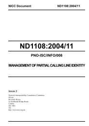
Power Meter<br />
Baluns<br />
Spectrum<br />
Analyser<br />
PC<br />
DSLAM<br />
Match<br />
Pad<br />
Line Simulator<br />
CPE<br />
PC<br />
PC<br />
Figure B.4 : <strong>Test</strong> Configuration for Measuring Downstream PSD<br />
Details of the impedance matching pad used are contained in Annex B.1.3 .<br />
1) Configure the DSLAM to implement an E-side electrical length (ESEL) 4 value of 30dB and<br />
configure a port with the default band profile.<br />
2) Set the line simulator to a loop length of 100m of TP-100 cable with noise injection disabled<br />
(i.e. noise free).<br />
3) Connect the CPE modem to the DSLAM using the <strong>Test</strong> Configuration shown in Figure B.4.<br />
4) Ensure that the CPE modem has attained synchronisation.<br />
5) Capture the downstream PSD and wideband power and compare against Part B of the BT<br />
ANFP [6].<br />
6) Check that the full 17MHz spectrum is used.<br />
Note that this test can be performed as part of requirement R.<strong>VDSL2</strong>.5.<br />
Expected Outcome – This test will be deemed a “Pass” if the full 17MHz spectrum is observed (i.e.<br />
use of downstream band between 12 and 17.664MHz) and that the downstream transmit power<br />
does not exceed 14.5dBm. If these criteria are not met, then the result is a “Fail”.<br />
R.<strong>VDSL2</strong>.3<br />
This requirement has been removed from the current revision of SIN 498.<br />
R.<strong>VDSL2</strong>.4 Compliance with UK ANFP Part C<br />
Refer to Annex C.<br />
R.<strong>VDSL2</strong>.5 Support of 998ADE17 Band <strong>Plan</strong><br />
4 The ITU-T G.993.2 Recommendation uses the term E-side Electrical Length (or ESEL) to refer to the loss of the cable connecting the exchange to<br />
the cabinet. The UK ANFP uses the term Cabinet Assigned Loss (or CAL) to describe the same parameter. In both cases, the insertion loss is<br />
measured at a frequency of 300kHz.<br />
<strong>NICC</strong> Standards Limited