âWires-onlyâ VDSL2 Modem Test Plan - NICC
âWires-onlyâ VDSL2 Modem Test Plan - NICC
âWires-onlyâ VDSL2 Modem Test Plan - NICC

Create successful ePaper yourself
Turn your PDF publications into a flip-book with our unique Google optimized e-Paper software.
36<br />
<strong>NICC</strong> ND 1436 V1.1.2 (2013-09)<br />
B.1.2.8.3 Ethernet, WAN and OAM<br />
NOTE : Additional <strong>Test</strong> requirements are for further study.<br />
R.<strong>VDSL2</strong>.18 R.OAM.4 Support of “Dying gasp”<br />
Description – The <strong>Modem</strong> should support “dying gasp” as defined in Section 11.3.3.2 of G.993.2<br />
[3] and Section 7.1.1.2.3 of G.997.1 [10].<br />
Note: “Dying gasp” is not a mandatory requirement in SIN 498 but CPE providers are encouraged<br />
to implement this in their modems as it will enable the Openreach <strong>Test</strong> & Diagnostic systems to<br />
differentiate between a modem being turned off by the end user (loss of power) or a loss of signal<br />
(loss of connectivity) caused by a potential network or home wiring issue. This will support CPE<br />
providers in their diagnostic approach to ensure that their End Users have checked relevant setup<br />
prior to submitting a fault to Openreach and thus ensure the correct cause of action and avoiding<br />
an unnecessary cost due to potential chargeable visits due to End User issues.<br />
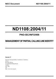
<strong>Test</strong> procedure –<br />
Noise Generator/<br />
Injector<br />
DSLAM<br />
Line Simulator<br />
NTE5 +<br />
iSSFP<br />
CPE<br />
PC<br />
PC<br />
Figure B.8 : <strong>Test</strong> Configuration for verifying “Dying Gasp”<br />
1) Configure DSLAM to implement an ESEL value of 30dB and configure a port with the<br />
default band profile.<br />
2) Connect the DSLAM and the CPE using the <strong>Test</strong> Configuration shown in Figure B.8.<br />
3) Set line simulator to simulate a loop length of 100m with noise injection disabled (i.e.<br />
noise free).<br />
4) Once the CPE has attained synchronisation, verify that no additional alarms have been<br />
raised on the EMS.<br />
5) Disconnect the plug from the power socket on the CPE. The modem should now power<br />
off.<br />
6) Check and record the EMS alarm messages.<br />
7) Replace power plug in socket and allow modem to resynchronise.<br />
8) Repeat steps 5 and 6 but this time switch off the power at the mains socket (or<br />
disconnect PSU from socket).<br />
9) Check and record the EMS alarm messages.<br />
<strong>NICC</strong> Standards Limited