RD Series Owner's Manual - Magnum Energy
RD Series Owner's Manual - Magnum Energy
RD Series Owner's Manual - Magnum Energy

Create successful ePaper yourself
Turn your PDF publications into a flip-book with our unique Google optimized e-Paper software.
Installation<br />
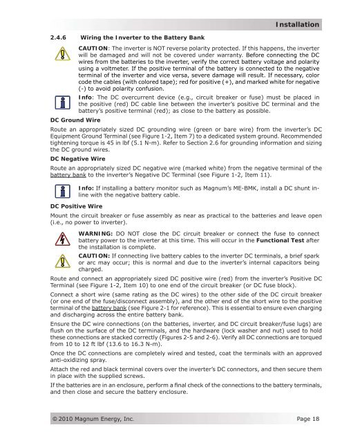
2.4.6 Wiring the Inverter to the Battery Bank<br />
CAUTION: The inverter is NOT reverse polarity protected. If this happens, the inverter<br />
will be damaged and will not be covered under warranty. Before connecting the DC<br />
wires from the batteries to the inverter, verify the correct battery voltage and polarity<br />
using a voltmeter. If the positive terminal of the battery is connected to the negative<br />
terminal of the inverter and vice versa, severe damage will result. If necessary, color<br />
code the cables (with colored tape); red for positive (+), and marked white for negative<br />
(-) to avoid polarity confusion.<br />
Info: The DC overcurrent device (e.g., circuit breaker or fuse) must be placed in<br />
the positive (red) DC cable line between the inverter’s positive DC terminal and the<br />
battery’s positive terminal (red); as close to the battery as possible.<br />
DC Ground Wire<br />
Route an appropriately sized DC grounding wire (green or bare wire) from the inverter’s DC<br />
Equipment Ground Terminal (see Figure 1-2, Item 7) to a dedicated system ground. Recommended<br />
tightening torque is 45 in lbf (5.1 N-m). Refer to Section 2.6 for grounding information and sizing<br />
the DC ground wires.<br />
DC Negative Wire<br />
Route an appropriately sized DC negative wire (marked white) from the negative terminal of the<br />
battery bank to the inverter’s Negative DC Terminal (see Figure 1-2, Item 11).<br />
Info: If installing a battery monitor such as <strong>Magnum</strong>’s ME-BMK, install a DC shunt inline<br />
with the negative battery cable.<br />
DC Positive Wire<br />
Mount the circuit breaker or fuse assembly as near as practical to the batteries and leave open<br />
(i.e., no power to inverter).<br />
WARNING: DO NOT close the DC circuit breaker or connect the fuse to connect<br />
battery power to the inverter at this time. This will occur in the Functional Test after<br />
the installation is complete.<br />
CAUTION: If connecting live battery cables to the inverter DC terminals, a brief spark<br />
or arc may occur; this is normal and due to the inverter’s internal capacitors being<br />
charged.<br />
Route and connect an appropriately sized DC positive wire (red) from the inverter’s Positive DC<br />
Terminal (see Figure 1-2, Item 10) to one end of the circuit breaker (or DC fuse block).<br />
Connect a short wire (same rating as the DC wires) to the other side of the DC circuit breaker<br />
(or one end of the fuse/disconnect assembly), and the other end of the short wire to the positive<br />
terminal of the battery bank (see Figure 2-1 for reference). This is essential to ensure even charging<br />
and discharging across the entire battery bank.<br />
Ensure the DC wire connections (on the batteries, inverter, and DC circuit breaker/fuse lugs) are<br />
flush on the surface of the DC terminals, and the hardware (lock washer and nut) used to hold<br />
these connections are stacked correctly (Figures 2-5 and 2-6). Verify all DC connections are torqued<br />
from 10 to 12 ft lbf (13.6 to 16.3 N-m).<br />
Once the DC connections are completely wired and tested, coat the terminals with an approved<br />
anti-oxidizing spray.<br />
Attach the red and black terminal covers over the inverter’s DC connectors, and then secure them<br />
in place with the supplied screws.<br />
If the batteries are in an enclosure, perform a final check of the connections to the battery terminals,<br />
and then close and secure the battery enclosure.<br />
© 2010 <strong>Magnum</strong> <strong>Energy</strong>, Inc.<br />
Page 18