RD Series Owner's Manual - Magnum Energy
RD Series Owner's Manual - Magnum Energy
RD Series Owner's Manual - Magnum Energy

You also want an ePaper? Increase the reach of your titles
YUMPU automatically turns print PDFs into web optimized ePapers that Google loves.
Installation<br />
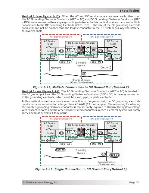
Method 2 (see Figure 2-17): When the AC and DC service panels are near each other, then<br />
the AC Grounding Electrode Conductor (GEC – AC) and DC Grounding Electrode Conductor (GEC<br />
– DC) can be connected to a single grounding electrode. In this method — since there are multiple<br />
connections to the DC Grounding Electrode (GEC – DC) — the size of the DC grounding electrode<br />
conductor can not be smaller than the largest conductor in the DC system (usually the batteryto-inverter<br />
cable).<br />
AC Electrical System<br />
DC Electrical System<br />
AC Service<br />
Panel<br />
GBB<br />
Neutral<br />
SBJ<br />
GEC-AC<br />
GC<br />
AC<br />
N eutral<br />
EGC - AC<br />
<strong>RD</strong> <strong>Series</strong> Inverter/Charger<br />
Hot<br />
Grounding<br />
System<br />
GE<br />
Positive<br />
DC<br />
N egative<br />
GC<br />
AC Ground D C Ground SBJ<br />
EGC - DC<br />
GEC-DC<br />
DC Service<br />
Panel<br />
Negative<br />
GBB<br />
Grounding Electrode<br />
(AC and DC sides shared)<br />
Figure 2-17, Multiple Connections to DC Ground Rod (Method 2)<br />
Method 3 (see Figure 2-18): The AC Grounding Electrode Conductor (GEC – AC) is bonded to<br />
the DC ground point and the DC Grounding Electrode Conductor (GEC – DC) is the only connection<br />
to the grounding electrode, which must be a rod, pipe, or plate electrode.<br />
In this method, since there is only one connection to the ground rod, the DC grounding electrode<br />
conductor is not required to be larger than #6 AWG (13 mm 2 ) copper. The reasoning for allowing<br />
this smaller grounding electrode conductor is that it is only required to stabilize the system voltage<br />
with respect to earth and the other properly sized conductors in each electrical system will safely<br />
carry any fault currents if they occur.<br />
AC Electrical System<br />
DC Electrical System<br />
AC Service<br />
Panel<br />
GBB<br />
Neutral<br />
SBJ<br />
GC<br />
AC<br />
N eutral<br />
EGC - AC<br />
<strong>RD</strong> <strong>Series</strong> Inverter/Charger<br />
Hot<br />
Positive<br />
DC<br />
N egative<br />
GC<br />
AC Ground D C Ground SBJ<br />
EGC - DC<br />
DC Service<br />
Panel<br />
Negative<br />
GBB<br />
GEC-AC<br />
Grounding<br />
System<br />
GE<br />
GEC-DC<br />
Grounding Electrode<br />
(DC side dedicated)<br />
Figure 2-18, Single Connection to DC Ground Rod (Method 3)<br />
© 2010 <strong>Magnum</strong> <strong>Energy</strong>, Inc.<br />
Page 30