RD Series Owner's Manual - Magnum Energy
RD Series Owner's Manual - Magnum Energy
RD Series Owner's Manual - Magnum Energy

You also want an ePaper? Increase the reach of your titles
YUMPU automatically turns print PDFs into web optimized ePapers that Google loves.
2.7 Inverter Notification Requirements<br />
Installation<br />
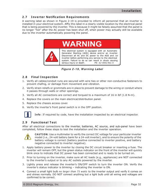
A warning label as shown in Figure 2-19 is provided to inform all personnel that an inverter is<br />
installed in your electrical system. Affix this label in a clearly visible location by the electrical panel<br />
that is being powered by the inverter. This is because it might be falsely assumed that the panel is<br />
no longer “hot” after the AC power has been shut off, when power may actually still be available<br />
due to the inverter automatically powering the panel.<br />
This electrical system is equipped with an Automatic<br />
Generator Starting (AGS) device and/or an inverter.<br />
Disconnect all AC and DC power to to the AGS and and/or<br />
inverter before performing any service to the electrical<br />
system. Failure to do so can result in shock causing<br />
serious iinjury or death . PN: 62-0002 Rev A<br />
Figure 2-19, Warning Label<br />
PN: 62-0002 Rev A<br />
2.8 Final Inspection<br />
1. Verify all cables/conduit runs are secured with wire ties or other non-conductive fasteners to<br />
prevent chafing, or damage from movement and vibration.<br />
2. Verify strain reliefs or grommets are in place to prevent damage to the wiring or conduit where<br />
it passes through walls or other openings.<br />
3. Verify all AC connections are correct and torqued to a maximum of 16 in lbf (1.8 N-m).<br />
4. Replace the covers on the main electrical/distribution panel.<br />
5. Replace the chassis access cover.<br />
6. Verify the inverter’s front panel switch is in the OFF position.<br />
Info: If required by code, have the installation inspected by an electrical inspector.<br />
2.9 Functional Test<br />
After all electrical connections to the inverter, batteries, AC source, and sub-panel have been<br />
completed, follow these steps to test the installation and the inverter operation.<br />
CAUTION: Use a multimeter to verify the correct DC voltage for your particular inverter<br />
model (i.e., 24-volt battery bank for a 24-volt inverter), and to ensure the polarity of the<br />
battery voltage is correct (battery positive connected to inverter positive, and battery<br />
negative connected to inverter negative).<br />
1. Apply battery power to the inverter by closing the DC circuit breaker or inserting a fuse. The<br />
inverter will remain OFF, but the green status indicator on the front of the inverter will quickly<br />
blink once to indicate that DC power has been connected and is ready to be turned on.<br />
2. Prior to turning on the inverter, make sure all AC loads (e.g., appliances) are NOT connected<br />
to the inverter’s output or to any AC outlets powered by the inverter.<br />
3. Lightly press and release the inverter’s ON/OFF switch to turn the inverter ON. Verify the<br />
inverter’s status indicator is blinking – indicating the inverter is ON.<br />
4. Connect a small light bulb no larger than 75 watts to the inverter output and verify it comes on<br />
and shines normally. DO NOT connect anything but a light bulb until all wiring and voltages are<br />
confirmed to be correct.<br />
© 2010 <strong>Magnum</strong> <strong>Energy</strong>, Inc.<br />
Page 32