RD Series Owner's Manual - Magnum Energy
RD Series Owner's Manual - Magnum Energy
RD Series Owner's Manual - Magnum Energy

You also want an ePaper? Increase the reach of your titles
YUMPU automatically turns print PDFs into web optimized ePapers that Google loves.
Installation<br />
2.6 Grounding Inverters<br />
The inverter/charger should always be connected to a permanent, grounded wiring system. An<br />
inverter system that is properly grounded will limit the risk of electrical shock, reduce radio frequency<br />
noise from the inverter and minimize excessive surge voltages induced by lightning. This is done<br />
by ensuring there is a well-defined, very low-resistance path from the electrical system to the<br />
grounding system. This low-resistance path helps stabilize the electrical system voltage with respect<br />
to ground and carries fault currents directly to ground if the electrical system malfunctions.<br />
To understand how the conductors in the electrical circuit will be connected to the system ground,<br />
the following terms should be understood:<br />
• Grounded Conductor (GC): The wire/cable in the electrical system that normally carries current (usually<br />
the AC neutral and/or the DC negative); and is intentionally connected or “bonded” to the ground<br />
system. This wire or the ends of this wire should be colored white or gray.<br />
• Equipment Grounding Conductor (EGC): A wire/cable that does not normally carry current and is used<br />
to connect the exposed metal parts of equipment that might be accidentally energized to the grounding<br />
electrode system or the grounded conductor. This wire or the ends of this wire should be green or green<br />
with a yellow stripe; or this wire can be bare copper.<br />
• Grounding Electrode Conductor (GEC): The wire/cable that does not normally carry current and connects<br />
the grounded conductor and/or the equipment grounding conductor to the grounding electrode at the<br />
service equipment.<br />
• Grounding Electrode (GE): A ground rod or conducting element that establishes an electrical connection<br />
to the earth.<br />
• System bonding jumper (SBJ) The connection between the grounded circuit conductor in the electrical<br />
system and the equipment grounding conductor at a separately derived system.<br />
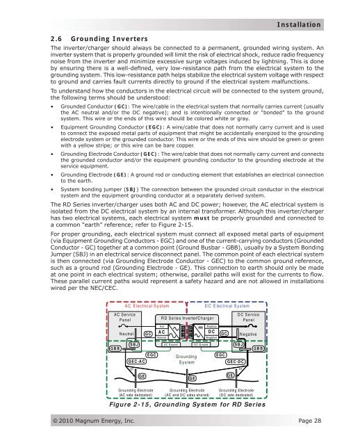
The <strong>RD</strong> <strong>Series</strong> inverter/charger uses both AC and DC power; however, the AC electrical system is<br />
isolated from the DC electrical system by an internal transformer. Although this inverter/charger<br />
has two electrical systems, each electrical system must be properly grounded and connected to<br />
a common “earth” reference; refer to Figure 2-15.<br />
For proper grounding, each electrical system must connect all exposed metal parts of equipment<br />
(via Equipment Grounding Conductors - EGC) and one of the current-carrying conductors (Grounded<br />
Conductor - GC) together at a common point (Ground Busbar - GBB), usually by a System Bonding<br />
Jumper (SBJ) in an electrical service disconnect panel. The common point of each electrical system<br />
is then connected (via Grounding Electrode Conductor - GEC) to the common ground reference,<br />
such as a ground rod (Grounding Electrode - GE). This connection to earth should only be made<br />
at one point in each electrical system; otherwise, parallel paths will exist for the currents to flow.<br />
These parallel current paths would represent a safety hazard and are not allowed in installations<br />
wired per the NEC/CEC.<br />
AC Service<br />
Panel<br />
GBB<br />
AC Electrical System<br />
Neutral<br />
SBJ<br />
GC<br />
EGC<br />
GEC-AC<br />
or<br />
GE<br />
Grounding Electrode<br />
(AC side dedicated)<br />
DC Electrical System<br />
DC Service<br />
<strong>RD</strong> <strong>Series</strong> Inverter/Charger<br />
Panel<br />
Hot<br />
AC<br />
Neutral<br />
Grounding<br />
System<br />
GE<br />
Positive<br />
DC<br />
N egative<br />
GC<br />
AC Ground DC Ground SBJ<br />
Grounding Electrode<br />
(AC and DC sides shared)<br />
EGC<br />
GEC-DC<br />
GE<br />
Negative<br />
Grounding Electrode<br />
(DC side dedicated)<br />
GBB<br />
Figure 2-15, Grounding System for <strong>RD</strong> <strong>Series</strong><br />
or<br />
© 2010 <strong>Magnum</strong> <strong>Energy</strong>, Inc.<br />
Page 28