RD Series Owner's Manual - Magnum Energy
RD Series Owner's Manual - Magnum Energy
RD Series Owner's Manual - Magnum Energy

Create successful ePaper yourself
Turn your PDF publications into a flip-book with our unique Google optimized e-Paper software.
Installation<br />
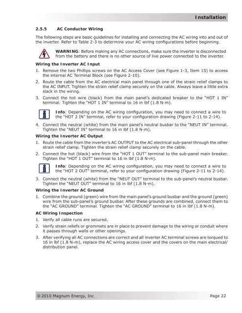
2.5.5 AC Conductor Wiring<br />
The following steps are basic guidelines for installing and connecting the AC wiring into and out of<br />
the inverter. Refer to Table 2-3 to determine your AC wiring configurations before beginning.<br />
WARNING: Before making any AC connections, make sure the inverter is disconnected<br />
from the battery and there is no other source of live power connected to the inverter.<br />
Wiring the Inverter AC Input<br />
1. Remove the two Phillips screws on the AC Access Cover (see Figure 1-3, Item 15) to access<br />
the internal AC Terminal Block (see Figure 2-10).<br />
2. Route the cable from the AC electrical main panel through one of the strain relief clamps to<br />
the AC INPUT. Tighten the strain relief clamp securely on the cable. Always leave a little extra<br />
slack in the wiring.<br />
3. Connect the hot wire (black) from the main panel’s dedicated breaker to the “HOT 1 IN”<br />
terminal. Tighten the “HOT 1 IN” terminal to 16 in lbf (1.8 N-m).<br />
Info: Depending on the AC wiring configuration, you may need to connect a wire to<br />
the “HOT 2 IN” terminal, refer to your configuration drawing (Figure 2-11 to 2-14).<br />
4. Connect the neutral (white) from the main panel’s neutral busbar to the “NEUT IN” terminal.<br />
Tighten the “NEUT IN” terminal to 16 in lbf (1.8 N-m).<br />
Wiring the Inverter AC Output<br />
1. Route the cable from the inverter’s AC OUTPUT to the AC electrical sub-panel through the other<br />
strain relief clamp. Tighten the strain relief clamp securely on the cable.<br />
2. Connect the hot (black) wire from the “HOT 1 OUT” terminal to the sub-panel main breaker.<br />
Tighten the “HOT 1 OUT” terminal to 16 in lbf (1.8 N-m).<br />
Info: Depending on the AC wiring configuration, you may need to connect a wire to<br />
the “HOT 2 OUT” terminal, refer to your configuration drawing (Figure 2-11 to 2-14).<br />
3. Connect the neutral (white) from the “NEUT OUT” terminal to the sub-panel’s neutral busbar.<br />
Tighten the “NEUT OUT” terminal to 16 in lbf (1.8 N-m).<br />
Wiring the Inverter AC Ground<br />
1. Combine the ground (green) wire from the main panel’s ground busbar and the ground (green)<br />
wire from the sub-panel’s ground busbar. After these grounds are combined, connect them to<br />
the “AC GROUND” terminal. Tighten the “AC GROUND” terminal to 16 in lbf (1.8 N-m).<br />
AC Wiring Inspection<br />
1. Verify all cable runs are secured.<br />
2. Verify strain reliefs or grommets are in place to prevent damage to the wiring or conduit where<br />
it passes through walls or other openings.<br />
3. After verifying all AC connections are correct and all inverter AC terminal screws are torqued to<br />
16 in lbf (1.8 N-m), replace the AC wiring access cover and the covers on the main electrical/<br />
distribution panel.<br />
© 2010 <strong>Magnum</strong> <strong>Energy</strong>, Inc.<br />
Page 22