PHOTOMOD VectOr (raster images processing) - Racurs
PHOTOMOD VectOr (raster images processing) - Racurs
PHOTOMOD VectOr (raster images processing) - Racurs

You also want an ePaper? Increase the reach of your titles
YUMPU automatically turns print PDFs into web optimized ePapers that Google loves.
<strong>PHOTOMOD</strong><br />
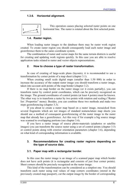
1.3.6. Horizontal alignment.<br />
This operation causes placing selected <strong>raster</strong> points on one<br />
horizontal line. The <strong>raster</strong> is rotated about the first selected point.<br />
1.4. Raster region.<br />
When loading <strong>raster</strong> <strong>images</strong> to the database there may be <strong>raster</strong> work region<br />
created. To create <strong>raster</strong> region you should consequently load each <strong>raster</strong> image and<br />
georeference them to the same coordinate system.<br />
The combination of <strong>raster</strong> and vector maps for the same terrain districts is useful<br />
for creating and updating work regions quickly. In this case you are able to resolve<br />
application tasks related to <strong>raster</strong> and vector objects representations.<br />
2. How to choose a type of <strong>raster</strong> transformation.<br />
In case of creating of large-scale plans (layouts), it is recommended to use a<br />
transformation by corner points of a map sheet (chapter 3.1).<br />
When creating small scale digital maps (smaller than 1:50 000) in order to<br />
increase the accuracy of the output <strong>raster</strong> image you should transform a <strong>raster</strong> image,<br />
taken into account arch points of the map border (chapter 3.2).<br />
If there is no map border on the <strong>raster</strong> image (or it exists partially), you can<br />
transform <strong>raster</strong> by control point coordinates, which can be precisely recognized on<br />
the image. The ground coordinates of control points (at least 4 points) must be known.<br />
The other way is to transform a <strong>raster</strong> by two points with rotation and scaling (“Raster<br />
list | Properties” menu). Besides, you can combine these two methods and make two<br />
steps georeferencing (chapter 3.3).<br />
If you about to create a <strong>raster</strong> map based on a <strong>raster</strong> image, mosaicked from<br />
several fragments which are not <strong>images</strong> of standard nomenclature map sheets you<br />
should use a method of consequent georeferencing of the <strong>raster</strong> image to the <strong>raster</strong><br />
map that already has a georeference. Act this way if for example a big source image<br />
was scanned to overlapping portions (see chapter 3.4).<br />
If you have a <strong>raster</strong> image of source photo-materials (airphotos or satellite<br />
<strong>images</strong>) you can transform the source <strong>raster</strong> using a set of control points (chapter 3.5)<br />
or control points along with exterior orientation parameters (chapter 3.6), depending<br />
on what kind of corresponding information is available.<br />
3. Recommendations for creating <strong>raster</strong> regions depending on<br />
the type of source data.<br />
3.1. Paper map with a rectangular border.<br />
In this case the <strong>raster</strong> image is an image of a scanned paper map which border<br />
does not have arch points (it is rectangular and consists of just four corner points).<br />
Sheet corners should be precisely recognized on the <strong>raster</strong> image.<br />
This kind of the transformation can be considered as a simplest one. You should<br />
transform each <strong>raster</strong> using real values of map corners coordinates (stored in the<br />
previously created map passport), cut the output image by the border of corresponding<br />
© 2009 6