Oxygen Analyzer Type ZRY/ZFK - Coulton Instrumentation
Oxygen Analyzer Type ZRY/ZFK - Coulton Instrumentation
Oxygen Analyzer Type ZRY/ZFK - Coulton Instrumentation

You also want an ePaper? Increase the reach of your titles
YUMPU automatically turns print PDFs into web optimized ePapers that Google loves.
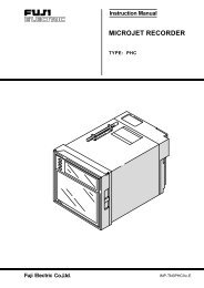
Instruction Manual<br />
ZIRCONIA OXYGEN<br />
ANALYZER CONVERTER<br />
TYPE: <strong>ZRY</strong><br />
OXYGEN ANALYZER<br />
Vol% O2<br />
INZ-TN1<strong>ZRY</strong>a-E
PREFACE<br />
We are grateful for your purchase of Fuji Electric’s Zirconia <strong>Oxygen</strong> <strong>Analyzer</strong> Converter (<strong>ZRY</strong>).<br />
• First read this instruction manual carefully until an adequate understanding is acquired, and then<br />
proceed to installation, operation and maintenance of the analyzer converter. Wrong handling may<br />
cause an accident or injury.<br />
• The specifications of this analyzer converter will be changed without prior notice for further product<br />
improvement.<br />
• Modification of this analyzer converter is strictly prohibited unless a written approval is obtained<br />
from the manufacturer. Fuji Electric will not bear any responsibility for a trouble caused by such<br />
a modification.<br />
• This instruction manual shall be stored by the person who actually uses the analyzer converter.<br />
• After reading the manual, be sure to store it at a place easier to access.<br />
• This instruction manual should be delivered to the end user without fail.<br />
Manufacturer:<br />
<strong>Type</strong>:<br />
Date of manufacture:<br />
Product nationality:<br />
Fuji Electric Co., Ltd.<br />
Described in Fuji Electric’s company nameplate on main frame<br />
Described in Fuji Electric’s company nameplate on main frame<br />
Japan<br />
Request<br />
• It is prohibited to transfer part or all of this manual without Fuji Electric’s<br />
permission in written format.<br />
• Description in this manual will be changed without prior notice for further<br />
improvement.<br />
© Fuji Electric Co., Ltd. 1998<br />
Issued in June, 1998<br />
Rev. 1st edition April, 2000<br />
i
CAUTION ON SAFETY<br />
First of all, read this “Caution on safety” carefully, and then use the analyzer in the correct way.<br />
• The cautionary descriptions listed here contain important information about safety, so they should always be<br />
observed. Those safety precautions are ranked 2 levels; DANGER and CAUTION.<br />
DANGER<br />
Wrong handling may cause a dangerous situation, in which there is a<br />
risk of death or heavy injury.<br />
CAUTION<br />
Wrong handling may invite a dangerous situation, in which there is a<br />
possibility of medium-level trouble or slight injury or only physical<br />
damage is predictable.<br />
• Even an undesirable action described in “ CAUTION ” may lead to a grave result depending on situation.<br />
Be sure to observe DANGER and CAUTION because they are both important for ensuring safety.<br />
Caution on installation and transport of gas analyzer<br />
DANGER<br />
CAUTION<br />
• This unit is not explosion-proof type. Do not use it in a place with<br />
explosive gases to prevent explosion, fire or other serious accidents.<br />
• This unit should be installed in a place which conforms to the conditions<br />
noted in the instruction manual. Otherwise, it may cause electric<br />
shocks, fire or malfunction of the unit.<br />
• During installation work, care should be taken to keep the unit free<br />
from entry of cable chips or other foreign objects. Otherwise, it may<br />
cause fire, trouble or malfunction of the unit.<br />
• For installation, observe the rule on it given in the instruction manual<br />
and select a place where the weight of gas analyzer can be endured.<br />
Installation at an unsuited place may cause turnover or fall and there<br />
is a risk of injury.<br />
• For lifting the gas analyzer, be sure to wear protective gloves. Bare<br />
hands may invite an injury.<br />
• Before transport, fix the casing so that it will not open. Otherwise, the<br />
casing may be separated and fall to cause an injury.<br />
• The gas analyzer is heavy. It should be transported carefully by two or<br />
more persons if manually required. Otherwise, body may be damaged<br />
or injured.<br />
Caution on piping<br />
DANGER<br />
• If leaked gas contains oxygen at a high concentration, there is a risk of<br />
fire.<br />
• Connect pipes correctly referring to the instruction manual. Wrong<br />
piping may cause gas leakage.<br />
ii
Caution on wiring<br />
CAUTION<br />
• The unit must be earthed as specified. Otherwise, it may cause electric<br />
shocks, malfunction, etc.<br />
• Be sure to use a power supply of correct rating. Connection of power<br />
supply of incorrect rating may cause fire.<br />
• Wiring work must be performed with the main power set to OFF to<br />
prevent electric shocks.<br />
• Use wiring materials that match the rating of the unit. Use of wiring<br />
materials out of rating may cause fire.<br />
Caution on use<br />
CAUTION<br />
• During operation, avoid opening the casing and touching the internal<br />
parts. Otherwise, you may suffer a burn or shock hazard.<br />
• Avoid touching the detector with bare hand during operation. Otherwise,<br />
you may suffer a burn because the detector may have reached a<br />
high temperature (about 800°C).<br />
• During operation, avoid removing and placing the detector on or near<br />
a combustible material. Otherwise, fire may occur.<br />
Caution on maintenance and check<br />
CAUTION<br />
• Before maintenance and check, be sure to turn off the main power<br />
supply and wait until the detector is cooled adequately. Otherwise,<br />
you may suffer a burn.<br />
• Before removing the detector from the flue for maintenance and check,<br />
make sure the furnace is stopped. Otherwise, you may suffer a burn.<br />
• Before working, take off a wrist watch, finger ring or the like metallic<br />
accessories. And never touch the instrument with a wet hand. Otherwise,<br />
you will have a shock hazard.<br />
• If the fuse is blown, eliminate the cause, and then replace it with the<br />
one of the same capacity and type as before. Otherwise, shock hazard<br />
or fault may be caused.<br />
Others<br />
CAUTION<br />
• If the cause of any fault cannot be determined despite reference to the<br />
instruction manual, be sure to contact your dealer or Fuji Electric’s<br />
technician in charge of adjustment. If the instrument is disassembled<br />
carelessly, you may have a shock hazard or injury.<br />
• Do not use a replacement part other than specified by the instrument<br />
maker. Otherwise, adequate performance will not be provided. Besides,<br />
an accident or fault may be caused.<br />
• Replacement parts such as a maintenance part should be disposed of<br />
as incombustibles.<br />
iii
CONTENTS<br />
PREFACE................................................................................................................................................ i<br />
CAUTION ON SAFETY ....................................................................................................................... ii<br />
CONTENTS .......................................................................................................................................... iv<br />
1. GENERAL DESCRIPTION ...........................................................................................................1<br />
1.1 Direct insertion type zirconia oxygen analyzer ................................................................................... 1<br />
1.2 Confirmation of delivered components ............................................................................................... 1<br />
1.3 Confirmation of type of delivered components................................................................................... 1<br />
2. NAME AND FUNCTION OF EACH PART ................................................................................. 2<br />
2.1 Name and function of converter part................................................................................................... 2<br />
2.2 Name and function of display and control panel................................................................................. 2<br />
3. INSTALLATION ............................................................................................................................ 3<br />
3.1 Location for installation ...................................................................................................................... 3<br />
3.2 Installation ........................................................................................................................................... 3<br />
4. WIRING AND PIPING .................................................................................................................. 4<br />
4.1 Before wiring ...................................................................................................................................... 4<br />
4.2 Wiring to each teminal ........................................................................................................................ 4<br />
4.3 Wiring and piping diagram ................................................................................................................. 5<br />
5. PREPARATION FOR OPERATION ............................................................................................. 6<br />
6. OPERATION AND STOP ............................................................................................................. 6<br />
6.1 Starting ................................................................................................................................................ 6<br />
6.2 Shutdown............................................................................................................................................. 6<br />
6.3 Key operation flow diagram (outline) ................................................................................................. 7<br />
6.4 Check on alarm data ............................................................................................................................ 8<br />
6.5 <strong>Oxygen</strong> detector standard output ........................................................................................................ 8<br />
7. SETTING OF CALIBRATION GAS CONCENTRATION .......................................................... 9<br />
7.1 How to set span calibration gas concentration .................................................................................... 9<br />
7.2 How to set zero calibration gas concentration .................................................................................... 9<br />
8. CALIBRATION ............................................................................................................................ 10<br />
8.1 Preparation ........................................................................................................................................ 10<br />
8.2 Manual calibration ............................................................................................................................ 10<br />
9. RANGE SELECTION .................................................................................................................. 11<br />
10. ADJUSTMENT ............................................................................................................................. 12<br />
10.1 Zirconia input signal adjustment ....................................................................................................... 12<br />
10.2 Temperature input adjustment ........................................................................................................... 13<br />
10.3 Current output adjustment ................................................................................................................. 14<br />
10.4 Setting of detector control temperature ............................................................................................. 15<br />
10.5 Selection of alarm contact output ...................................................................................................... 16<br />
11. MAINTENANCE AND CHECK ................................................................................................. 17<br />
11.1 Check................................................................................................................................................. 17<br />
11.2 Fuse replacement ............................................................................................................................... 17<br />
11.3 Troubleshooting ................................................................................................................................ 18<br />
12. APPENDIX ................................................................................................................................... 19<br />
12.1 Specification ...................................................................................................................................... 19<br />
12.2 Designation of type (PILC code table).............................................................................................. 20<br />
12.3 Outline diagram (unit:mm) ............................................................................................................... 22<br />
iv
1. GENERAL DESCRIPTION<br />
This instruction manual describes the installation, operation and maintenance of the single-channel type<br />
converter, so read through it before using the converter. For the sensor, flow guide tube used with the converter,<br />
refer to relevant instruction manuals.<br />
1.1 Direct insertion type zirconia oxygen analyzer<br />
The direct insertion type zirconia oxygen analyzer consists of a direct insertion type zirconia detector (type<br />
<strong>ZFK</strong>) and converter (type <strong>ZRY</strong>).<br />
It is used to measure oxygen concentration in waste gas during combustion for controlling gas combustion.<br />
1.2 Confirmation of delivered components<br />
Inspect the external appearance and number of accessories to confirm there is no damage or shortage of parts.<br />
List of components and accessories<br />
Converter<br />
Accessories of converter<br />
• Power fuse (0.5A) ------------------------------ 1<br />
• Heater fuse (3A)-------------------------------- 1<br />
CAUTION<br />
Power voltage for the converter must conform to that for the detector (<strong>ZFK</strong>2 or 5)<br />
to be connected. Don’t use any power voltage different from the power specifications<br />
of the detector.<br />
Because it may result in damage to the sensor.<br />
100/115V AC for <strong>ZFK</strong> 2 14-0<br />
5<br />
200/220V AC, or 230V AC for <strong>ZFK</strong> 2 3 4-0<br />
5 5<br />
1.3 Confirmation of type of delivered components<br />
Check model name on specification nameplate to confirm that the delivered components are as described in<br />
Item 12.2 Designation of type (PILC code table).<br />
-1-
2. NAME AND FUNCTION OF EACH PART<br />
2.1 Name and function of converter part<br />
<br />
OXYGEN ANALYZER<br />
Vol% O2<br />
<br />
FUSE AC250V<br />
3.15A T 500mA T<br />
HEATER POWER<br />
<br />
<br />
<br />
<br />
<br />
<br />
No.<br />
<br />
<br />
<br />
<br />
<br />
<br />
<br />
Name<br />
Cover fixing screw (4 places)<br />
Operation panel fixing screw (3 places)<br />
Fuse (0.5A)<br />
Fuse (3A)<br />
Terminal block<br />
Cable inlet<br />
Cable gland<br />
Function<br />
Screw for opening or closing the cover.<br />
Screw for fixing the operation panel to the case.<br />
Fuse for the power supply of the converter.<br />
Fuse for the heater for O 2<br />
sensor.<br />
Connect cables from external equipments.<br />
Use to insert external cable.<br />
Cable inlet to insert the exclusive cable for the sensor.<br />
2.2 Name and function of display and control panel<br />
1<br />
OXYGEN ANALYZER<br />
Vol% O2<br />
ZERO SPAN CAL. ESC<br />
+ - ENT SET<br />
1 2 3 4 5 6 7 8 9 10 111213 14<br />
+ - + - + -<br />
N L<br />
T.C Zr.SIG A.OUT ALARM HEATER FG POWER<br />
FUSE AC250V<br />
3.15A T 500mA T<br />
HEATER<br />
POWER<br />
2 3 4 5<br />
No.<br />
<br />
<br />
<br />
<br />
<br />
Name<br />
<strong>Oxygen</strong> concentration<br />
display<br />
ZERO key<br />
SPAN key<br />
CAL key<br />
ESC key<br />
}<br />
Function<br />
Displays oxygen gas concentration.<br />
Refer to each operation procedure flow in chapter 6 to<br />
10.<br />
-2-
3. INSTALLATION<br />
CAUTION<br />
• Install the analyzer safely and securely so that it will not fall.<br />
3.1 Location for installation<br />
The location for installation should meet the following conditions.<br />
(1) Space for routine inspection and wiring available.<br />
(2) Vibration, dust, dirt and humidity are minimal.<br />
(3) No direct influence of radiation from heating furnace or the like (converter).<br />
(4) Non-corrosive atmospheric environment.<br />
(5) No electric machinery nearby, which may cause noise trouble (such as motor, transformer) or produce<br />
electromagnetic and electrostatic induction.<br />
(6) Ambient temperature within -10 to +50 and ambient humidity less than 90%RH (converter).<br />
3.2 Installation<br />
3.2.1 Panel mounting<br />
Mounting dimension (unit ; mm)<br />
<br />
<br />
<br />
<br />
Mounting method<br />
Panel face<br />
No. Name Piece<br />
1 Converter 1<br />
2 Pan head screw<br />
M8 4<br />
Excluded from the<br />
scope of supply<br />
(<br />
(<br />
<br />
<br />
-3-
4. WIRING AND PIPING<br />
CAUTIONS<br />
• Wiring work must be carried out with all power supplies turned off.<br />
Otherwise, you may suffer electric shock.<br />
• The analyzer should be grounded without fail (Class 3 grounding).<br />
4.1 Before wiring<br />
Power supply voltage to the converter should match with that of the sensor (<strong>Type</strong> <strong>ZFK</strong>2 or 5).<br />
For wiring to the power supply, use 600V vinyl insulation power cable (JISC3307) of 1.25mm 2<br />
or equivalent.<br />
For the wiring of thermocouple, be sure to use a compensating wire.<br />
Exclusive cable (6 cores in total) between the sensor and converter should be installed in a cable<br />
conduit for protection. It should be separated from power cable for prevention of noise.<br />
For use of the exclusive cable, see Item 12.2 Designation of type.<br />
Output signal cable should be separated more than 30cm away from power line to prevent effect<br />
of induction noise. Shielded cables should be used and grounded at one point with M4 screw<br />
with toothed washer.<br />
Note) When connecting cables to external terminal block, recommended insulation sleeve solderless<br />
terminals should be used (for M4 screw).<br />
4.2 Wiring to each teminal<br />
OXYGEN ANALYZER<br />
Vol% O2<br />
FUSE AC250V<br />
3.15A T 500mA T<br />
HEATER POWER<br />
External terminal block<br />
1 2 3 4 5 6 7 8 9 10 111213 14<br />
N L<br />
-4-<br />
THERMO-<br />
COUPLE<br />
SIGNAL<br />
ZIRCONIA<br />
SIGNAL<br />
DC420mA<br />
ANALOG<br />
OUTPUT<br />
ALARM<br />
CONTACT<br />
OUTPUT<br />
SIGNAL<br />
DETECTOR<br />
HEATER<br />
POWER<br />
SUPPLY<br />
POWER<br />
SUPPLY
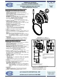
4.3 Wiring and piping diagram<br />
With flow guide tube<br />
Flow guide<br />
tube<br />
Sensor<br />
4-core exclusive<br />
cable<br />
Converter<br />
<br />
-5-<br />
Calibration<br />
gas<br />
inlet<br />
1R/min<br />
<br />
<br />
<br />
<br />
<br />
<br />
Red<br />
White<br />
Blue<br />
Yellow<br />
Black<br />
White<br />
2-core<br />
exclusive cable<br />
Flow rater<br />
0.2 to 2R/min<br />
Manual operated<br />
valve for zero gas<br />
Manual operated<br />
valve for span gas<br />
Pressure reducing<br />
valve for standard<br />
gas<br />
AC power supply<br />
Standard gas<br />
O2/N2 (ZBM)<br />
Pressure reducing valve<br />
<strong>Instrumentation</strong> air<br />
or standard gas (ZBM)
5. PREPARATION FOR OPERATION<br />
Preparation can be performed after installation or on the bench.<br />
Wiring check (Refer to 4.2, 4.3)<br />
h<br />
<br />
Confirmation of the power supply specifications (Confirm the specifications of the main power supply<br />
and voltage.)<br />
h<br />
Piping check (Refer to 4.3)<br />
h<br />
<br />
<br />
<br />
<br />
Power ON<br />
• Turn ON the power<br />
• LED lighted.<br />
• The analyzer is set in measurement display mode after warm-up (15 minutes).<br />
h<br />
Warmup (After 15 minutes from power ON, accurate measurement data may be obtained.)<br />
h<br />
Standard gas (composition gas) concentration setting<br />
For the standard gas concentration to be used, see Chapter 7.<br />
h<br />
Calibration<br />
At the first operation, perform manual calibration after warmup using a calibration gas.<br />
Refer to chapter 8 for calibration procedures.<br />
h<br />
Operation<br />
6. OPERATION AND STOP<br />
6.1 Starting<br />
After correct wiring and piping has been completed, turn the converter power ON, and measuring operation<br />
will start.<br />
Note : 15 minutes is required for warming-up after power ON.<br />
Caution before starting operation<br />
Furnace operation should be started after 15 minutes. or more of warmup time has elapsed.<br />
When a sensor is to be installed in a furnace during operation, take care to blow out harmful<br />
gas from the furnace and then install the fully warmed up sensor quickly.<br />
6.2 Shutdown<br />
(1) When a process (furnace etc.) is to be shutdown for a short time (about one week)<br />
The sensor should be operated continuously to avoid possible deterioration of platinum electrodes<br />
and destruction of its element by repeating power ON-OFF operation in a wet condition (depending<br />
on the condition in furnace and/or ambient conditions)<br />
(2) When a process (furnace etc.) is to be shutdown for a long time<br />
Turn OFF the analyzer after gas in the furnace has been replaced completely by ambient air.<br />
-6-
6.3 Key operation flow diagram (outline)<br />
ZERO<br />
All of 3 digits blink<br />
Zero calibration (Item 8.2)<br />
SPAN<br />
All of 3 digits blink<br />
Span calibration (Item 8.2)<br />
ZERO<br />
<br />
ESC<br />
1st digit blinks<br />
Calibration gas concentration setting zero (Item 7.2)<br />
SPAN<br />
<br />
ESC<br />
1st digit blinks<br />
Calibration gas concentration setting span (Item 7.1)<br />
ENT ESC<br />
Keep key on for 5 sec. Decimal point in<br />
1st digit blinks<br />
ENT<br />
Decimal point in<br />
2nd digit blinks<br />
ZERO<br />
SPAN<br />
2nd digit blinks<br />
Zirconia input signal<br />
adjustment zero (Item 10.1)<br />
Zirconia input signal<br />
adjustment span (Item 10.1)<br />
3rd digit blinks<br />
ZERO<br />
Temperature input adjustment zero (Item 10.2)<br />
2nd digit blinks in 700 display.<br />
SPAN<br />
Temperature input adjustment span (Item 10.2)<br />
3rd digit blinks in 800 display.<br />
ENT<br />
Keep key on for 5 sec.<br />
ZERO ESC<br />
000 is displayed.<br />
Current output adjustment zero (Item 10.3)<br />
SPAN <br />
ESC<br />
100 is displayed.<br />
Current output adjustment span (Item 10.3)<br />
ESC<br />
Keep key on for 3 sec.<br />
Detector<br />
temperature<br />
display<br />
ESC<br />
Keep key on<br />
for 3 sec.<br />
Alarm data display (Item 6.4)<br />
CAL<br />
error clear (calibration error only)<br />
Note) How to cancel operation<br />
Press the ESC key during setting to cancel operation midway, returning to measurement display.<br />
-7-
6.4 Check on alarm data<br />
When a fault (error) warning output appears at the converter alarm contact output terminals (No. 7 and No.<br />
8), the alarm data can be checked by the following operation.<br />
Measurement<br />
display<br />
ESC<br />
Keep key on for 3 sec.<br />
ESC<br />
Keep key on for 3 sec.<br />
Alarm data display<br />
CAL<br />
error clear (calibration error only)<br />
After checking the alarm data, press the CAL key and the alarm of zero/span calibration error will be<br />
cleared.<br />
Alarm data<br />
The 3rd digit<br />
Temperature error<br />
The 2nd digit<br />
Zero calibration error<br />
The 1st digit<br />
Span calibration error<br />
; 50°C (or more) higher than the detector control temperature<br />
; 50°C (or less) lower than the detector control temperature<br />
; Difference of more than 5%O2 between zero calibration gas<br />
concentration and zero calibration set value<br />
Blank; Normal<br />
; Difference of more than 5%O2 between span calibration gas<br />
concentration and span calibration set value<br />
Blank; Normal<br />
Conditions of converter alarm contact output (between No.7 and No.8 terminals)<br />
The 5th digit of<br />
converter code<br />
symbols<br />
Power OFF<br />
Power ON,<br />
normal<br />
Power ON,<br />
alarm<br />
B Open Open Closed<br />
C Open Closed Open<br />
6.5 <strong>Oxygen</strong> detector standard output<br />
O2 concentration<br />
%<br />
Output value<br />
mV<br />
O2 concentration<br />
%<br />
Output value<br />
mV<br />
O2 concentration<br />
%<br />
Output value<br />
mV<br />
0.01<br />
168.15<br />
5.0<br />
31.20<br />
25.0<br />
-4.266<br />
0.1<br />
117.41<br />
10.0<br />
15.93<br />
30.0<br />
-8.284<br />
0.5<br />
81.94<br />
15.0<br />
6.991<br />
40.0<br />
-14.623<br />
1.0<br />
66.67<br />
20.0<br />
0.651<br />
50.0<br />
-19.54<br />
1.5<br />
57.73<br />
20.6<br />
0<br />
2.0<br />
51.39<br />
21.0<br />
-0.4238<br />
-8-
7. SETTING OF CALIBRATION GAS CONCENTRATION<br />
While setting zero/span calibration concentration, press the ZERO key once, then the number of the digit<br />
increases by one digit, and press the SPAN key, then the number of the digit decreases by one digit. Setting<br />
digit is moved to the right by one by pressing the ENT key. However, if the ENT is pressed while setting the<br />
3rd digit, calibration concentration setting will be ended.<br />
Note) Pressing the ESC key allows the setting to be canceled midway.<br />
7.1 How to set span calibration gas concentration<br />
Description<br />
• Set span calibration gas concentration. Use air generally.<br />
• For air, set 20.6% O 2<br />
.<br />
• The settable range is from 10.0 to 29.9% O 2<br />
.<br />
Order<br />
<br />
<br />
<br />
<br />
Operation<br />
Key operation<br />
SPAN + ESC<br />
ENT , ZERO<br />
ENT , ZERO<br />
ENT<br />
How to set the span calibration gas concentration to 21.0% O 2<br />
.<br />
(It is generally set to 20.9% O 2<br />
before shipment).<br />
Description<br />
Displayed message<br />
Press the SPAN key and ESC key simultaneously,<br />
then the lamp begins to blink (the<br />
number in the 1st digit blinks).<br />
Press the ENT key to blink the 2nd digit. Press<br />
the ZERO key to change “0” to “1”.<br />
Press the ENT key to blink the 3rd digit. Press<br />
the ZERO key (increase) to change “9” to “0”.<br />
Press the ENT key, then the display set to 21.0<br />
returns to measurement display status.<br />
To cancel the setting, press the ESC key.<br />
Measurement diaplay<br />
7.2 How to set zero calibration gas concentration<br />
Description<br />
• Set zero calibration gas concentration. Set the value specified on the gas cylinder.<br />
• For zero gas, Use O 2<br />
gas of 1.01% or less.<br />
• The settable range is from 0.00 to 99.9% O 2<br />
.<br />
Order<br />
<br />
<br />
Operation<br />
Key operation<br />
ZERO + ESC<br />
ENT , ENT ,<br />
SPAN<br />
How to set the zero calibration gas concentration to 1.00% O 2<br />
.<br />
(It is generally set to 1.01% O 2<br />
before shipment).<br />
Description<br />
Press the ZERO key and ESC key simultaneously,<br />
then the lamp begins to blink (the<br />
number in the 1st digit blinks).<br />
Press the ENT key twice to blink 3rd digit.<br />
Press the SPAN key (decrease) to change “1” to<br />
“0”.<br />
Displayed message<br />
<br />
ENT<br />
Press the ENT key, then the display that is set<br />
to 1.00 returns to measurement display status.<br />
Measurement diaplay<br />
To cancel the setting, press the ESC key.<br />
-9-
8. CALIBRATION<br />
In order to maintain good accuracy, proper calibration using calibration gas is necessary.<br />
Perform manual operation (Refer to 8.2).<br />
8.1 Preparation<br />
• Wiring/piping check<br />
Wiring and piping work should be made correctly referring to Item. 4.3. The main plug of standard gas<br />
should be left open. Since high pressure is present at piping connections, use blind-nut type joints and<br />
take special care with regard to air-tightness. Calibration gas flow should be 1 to 1.5r/min.<br />
• Setting of calibration gas concentration<br />
Referring to Chapter 7 “Setting of calibration gas concentration”, set the oxygen concentration in standard<br />
gas cylinder to be used.<br />
8.2 Manual calibration<br />
Caution before operation<br />
• Span/zero is calibrated once.<br />
• Calibration should be performed in the order of span and zero.<br />
• For calibration, allow calibration gas to flow into the sensor. When the sensor output signal is stabilized,<br />
key operation is performed to complete the processing.<br />
Order<br />
<br />
Operation<br />
Key operation<br />
Performing span calibration.<br />
Description<br />
Open the stop valve to flow span gas.<br />
Displayed message<br />
Measurement diaplay<br />
<br />
SPAN<br />
Press SPAN , then the message at right appears.<br />
All of 3 digits blink.<br />
<br />
<br />
ENT<br />
When display is stabilized, press ENT key and<br />
span calibration is completed.<br />
Close the stop valve.<br />
To cancel span calibration, press the ESC key.<br />
(All of 3 digits blink)<br />
Measurement diaplay<br />
Order<br />
<br />
Operation<br />
Key operation<br />
Performing zero calibration.<br />
Description<br />
Open the stop valve to flow zero gas.<br />
Displayed message<br />
Measurement diaplay<br />
<br />
ZERO<br />
Press ZERO , then the message at right<br />
appears. All of 3 digits blink.<br />
<br />
<br />
ENT<br />
When display is stabilized, press ENT key and<br />
zero calibration is completed.<br />
Close the stop valve.<br />
To cancel span calibration, press the ESC key.<br />
(All of 3 digits blink)<br />
Measurement diaplay<br />
-10-
9. RANGE SELECTION<br />
Open the door by removing 4 screws (M5).<br />
Remove 3 mounting screws (M3) fastening the operation panel. Remove the operation panel.<br />
Set the range selection switch at the near of the operation panel at range position.<br />
Operation panel<br />
J1 : 0 to 10%range<br />
J2 : 0 to 5%range<br />
J3 : 0 to 25%range<br />
Set before delivery<br />
-11-
10. ADJUSTMENT<br />
10.1 Zirconia input signal adjustment<br />
Description<br />
• This is used to adjust zero/span input of zirconia sensor signal.<br />
• This adjustment should be made when required accuracy cannot be obtained after calibration.<br />
In general, do not perform the above operation because it is based on the factory adjustment mode.<br />
(1) How to adjust zero input<br />
Order<br />
Operation (example)<br />
Key operation<br />
How to adjust zero input<br />
Description<br />
Displayed message<br />
<br />
Apply a voltage of 0±0.01mV to external<br />
terminals of 3(+) and 4( ).<br />
<br />
ENT + ESC<br />
Hold down the ENT key and ESC key<br />
simultaneously for more than 5 seconds, then<br />
the decimal point in the 1st digit begins to<br />
blink.<br />
<br />
ENT<br />
Press the ENT key, then the decimal point in<br />
the 2nd digit begins to blink.<br />
<br />
ZERO<br />
Press the ZERO key to blink the number in the<br />
2nd digit.<br />
<br />
ENT<br />
After confirming that voltage is applied to the<br />
terminals, press the ENT key, and then zero<br />
input adjustment can be performed.<br />
To cancel adjustment, press the ESC key.<br />
(2) How to adjust span input<br />
Order<br />
Operation (example)<br />
Key operation<br />
How to adjust span input<br />
Description<br />
Displayed message<br />
<br />
Apply a voltage of 50±0.01mV to external<br />
terminals of 3(+) and 4( ).<br />
<br />
ENT + ESC<br />
Hold down the ENT key and ESC key<br />
simultaneously for more than 5 seconds, then<br />
the decimal point in the 1st digit begins to<br />
blink.<br />
<br />
ENT<br />
Press the ENT key, then the decimal point in<br />
the 2nd digit begins to blink.<br />
<br />
SPAN<br />
Press the SPAN key to blink the number in the<br />
3rd digit.<br />
<br />
ENT<br />
After confirming that voltage is applied to the<br />
terminals, press the ENT key, and then span<br />
input adjustment can be performed.<br />
To cancel adjustment, press the ESC key.<br />
-12-
10.2 Temperature input adjustment<br />
Description<br />
• This is used to adjust zero/span adjustment of the thermocouple.<br />
In general, do not perform the above operation because it is based on the factory adjustment mode.<br />
(1) How to perform zero adjustment of thermocouple input<br />
Order<br />
<br />
Operation (example)<br />
Key operation<br />
How to perform zero adjustment of thermocouple input<br />
Description<br />
Apply a voltage confirming to 700 to external<br />
terminals, 1(+) and 2(-).<br />
Displayed message<br />
<br />
<br />
<br />
ENT + ESC<br />
ZERO<br />
ENT<br />
Hold down the ENT key and ESC key simultaneously<br />
for more than 5 seconds, then the decimal<br />
point in the 1st digit begins to blink.<br />
Press the ZERO key, 2nd digit blinks in 700 display.<br />
After confirming that voltage is applied to the terminals,<br />
press the ENT key, and then zero adjustment can<br />
be performed.<br />
To cancel adjustment, press the ESC key.<br />
(2) How to perform span adjustment of thermocouple input<br />
Order<br />
Operation (example)<br />
Key operation<br />
How to perform span adjustment of thermocouple input<br />
Description<br />
Displayed message<br />
<br />
<br />
ENT + ESC<br />
Apply a voltage confirming to 800 to external<br />
terminals, 1(+) and 2(-).<br />
Hold down the ENT key and ESC key simultaneously<br />
for more than 5 seconds, then the decimal<br />
point in the 1st digit begins to blink.<br />
<br />
<br />
SPAN<br />
ENT<br />
Press the SPAN key, 3rd digit blinks in 800 display.<br />
After confirming that voltage is applied to the terminals,<br />
press the ENT key, and then span adjustment<br />
can be performed.<br />
To cancel adjustment, press the ESC key.<br />
-13-
10.3 Current output adjustment<br />
Description<br />
• This adjustment should be made when<br />
required accuracy can not be obtained after<br />
calibration.<br />
This is adjusted prior to delivery, so no<br />
further adjustment is required for normal<br />
operation.<br />
• Adjust current by connecting an ammeter<br />
and a load resistor of 250Ω to external<br />
terminals 5(+) and 6( ).<br />
<br />
250Ω<br />
Ammeter<br />
<br />
<br />
Order<br />
Operation (example)<br />
Key operation<br />
How to perform zero adjustment of current output<br />
Description<br />
Displayed message<br />
<br />
ENT<br />
Hold down the ENT key for more than 5<br />
seconds, then the decimal point in the 3rd digit<br />
begins to blink.<br />
<br />
ZERO + ESC<br />
Press the ZERO key and ESC key simultaneously,<br />
and zero adjustment mode (000<br />
display) is displayed.<br />
<br />
SPAN or<br />
SPAN + ESC<br />
Press the SPAN key (increase) or press SPAN<br />
key + ESC key simultaneously (decrease) so<br />
that the ammeter may read 4mA.<br />
<br />
ENT<br />
When the ammeter reads 4±0.05mA, press the<br />
ENT key. Zero adjustment is performed.<br />
To cancel zero adjustment, press the ESC key.<br />
Order<br />
Operation (example)<br />
Key operation<br />
How to perform span adjustment of current output<br />
Description<br />
Displayed message<br />
<br />
ENT<br />
Hold down the ENT key for more than 5<br />
seconds, then the decimal point in the 3rd digit<br />
begins to blink.<br />
<br />
SPAN + ESC<br />
Press the SPAN key and ESC key simultaneously,<br />
and span adjustment mode (100<br />
display) is displayed.<br />
<br />
ZERO or<br />
ZERO + ESC<br />
Press the ZERO key (increase) or press ZERO<br />
key + ESC key simultaneously (decrease) so<br />
that the ammeter may read 20mA.<br />
<br />
ENT<br />
When the ammeter reads 20±0.05mA, press the<br />
ENT key. Span adjustment is performed.<br />
To cancel span adjustment, press the ESC key.<br />
-14-
10.4 Setting of detector control temperature<br />
Description<br />
• Setting of control temperature is required according to types of the detector to be connected.<br />
<strong>Type</strong> of detector and control temperature<br />
<strong>ZFK</strong>2 (general use type) .... Set to 800°C<br />
<strong>ZFK</strong>5 (corrosion-proof type) ... Set to 750°C<br />
In general, do not perform the above operation because it is based on the factory adjustment mode.<br />
When the detector needs to be replaced with another type, it becomes necessary to change the set value.<br />
Order<br />
<br />
<br />
<br />
<br />
<br />
Order<br />
<br />
<br />
<br />
<br />
<br />
Operation (example)<br />
Key operation<br />
ENT + ESC<br />
ZERO<br />
SPAN<br />
ZERO<br />
ENT<br />
(or ESC )<br />
Setting to 750°C (<strong>ZFK</strong>5)<br />
Description<br />
Press the ENT key and ESC key at the same<br />
time for more than 5 seconds, and the decimal<br />
point in the lst digit begins to blink.<br />
When the ZERO key is pressed, the detector is<br />
set in the temperature control mode with the figure<br />
700 displayed and the 2nd digit begins to blink.<br />
Next, press the SPAN key. The figure “7” in<br />
the 1st digit begins to blink.<br />
Then, press the ZERO key. The figure “7”<br />
blinking in the 1st digit disappears and the 2nd<br />
digit begins to blink.<br />
Press the ENT key (or ESC key), and the<br />
control temperature is set to 750°C when the<br />
display returns to the measurement mode.<br />
To cancel the above operation, press the ESC key.<br />
* Do not press the ESC key under the condition of .<br />
Operation (example)<br />
Key operation<br />
ENT + ESC<br />
SPAN<br />
ZERO<br />
SPAN<br />
ENT<br />
(or ESC )<br />
Setting to 800°C (<strong>ZFK</strong>2)<br />
Description<br />
Press the ENT key and ESC key at the same<br />
time for more than 5 seconds, and the decimal<br />
point in the lst digit begins to blink.<br />
When the SPAN key is pressed, the detector is<br />
set in the temperature control mode with the figure<br />
800 displayed and the 2nd digit begins to blink.<br />
Next, press the ZERO key. The figure “8” in<br />
the 1st digit begins to blink.<br />
Then, press the SPAN key. The figure “8”<br />
blinking in the 1st digit disappears and the 3rd<br />
digit begins to blink.<br />
Press the ENT key (or ESC key), and the<br />
control temperature is set to 800°C when the<br />
display returns to the measurement mode.<br />
To cancel the above operation, press the ESC key.<br />
* Do not press the ESC key under the condition of .<br />
Displayed message<br />
Measurement display<br />
Displayed message<br />
Measurement display<br />
-15-
10.5 Selection of alarm contact output<br />
Description<br />
• Select the converter alarm contact output.<br />
• Select the contact output from the 5th digit of the converter code symbols.<br />
The 5th digit of code symbol:<br />
B.... Normal Open contact is selected.<br />
C.... Normal Close contact is selected.<br />
For details of alarm contact output, refer to Item 6.4 Check on alarm data (Page 8).<br />
In general, do not perform the above operation because it is based on the factory adjustment mode.<br />
Order<br />
<br />
<br />
<br />
<br />
Operation (example)<br />
ENT<br />
Key operation<br />
ENT + ESC<br />
ZERO<br />
ENT<br />
Selection of alarm contact output<br />
Description<br />
When the ENT key is pressed for more than 5<br />
seconds, the decimal point in the 3rd digit<br />
begins to blink.<br />
Press the ENT key and ESC key at the same<br />
time to display the setting of the present contact<br />
output.<br />
Normal Open contact<br />
Normal Close contact<br />
By pressing the ZERO key,<br />
are selected alternately.<br />
and<br />
By pressing the ENT key, the setting is finished<br />
when the display returns to the measurement<br />
mode.<br />
To cancel the above operation, press the ESC key.<br />
Displayed message<br />
Normal Open contact<br />
Normal Close contact<br />
Measurement display<br />
-16-
11. MAINTENANCE AND CHECK<br />
11.1 Check<br />
In order to keep the instrumentation operating in good condition, perform the following periodical maintenance<br />
and check.<br />
Perform maintenance and check once every year or 2, or at time of furnace check.<br />
Check items<br />
Measures<br />
Zero, span calibration Calibrate once every week (Refer to Chapter 8 “Calibration”)<br />
Daily<br />
check<br />
Periodical<br />
check<br />
Deterioration of packings<br />
and O-rings<br />
Check for loose cable<br />
ground<br />
Check the remain pressure<br />
in the calibration gas<br />
cylinder<br />
Clogging or corrosion of<br />
flow guide tubes<br />
Clogging or corrosion of<br />
ejector type sampling prove<br />
Clogging of air outlet of<br />
ejectors<br />
If deteriorated, replace with new ones.<br />
Retighten or replace the packing.<br />
Check the amount using primary pressure.<br />
Remove the flow guide tube from the furnace wall, remove the<br />
detector and wash the flow guide tube with water.<br />
Remove the ejector from the furnace wall, disassemble the<br />
prove and wash it with water.<br />
Remove the ejector from the furnace wall and clean the air<br />
outlet located in the heat insulation layer of the furnace wall.<br />
11.2 Fuse replacement<br />
When a fuse blows, turn off the power switch, and replace the fuse after investigating the cause.<br />
Open the front cover of the sensor. Two<br />
fuses are located at lower right. The right<br />
fuse is for protection of the sensor circuit<br />
and the left one is for protection of the<br />
heater.<br />
Take care that these fuses are different<br />
each other in the rated current.<br />
For replacement, use a vessel style (flatblade)<br />
screwdriver or coin.<br />
Push down the cap on the fuse holder and<br />
rotate about 1/4 turn counterclockwise<br />
until the cap is removed from the fuse<br />
holder.<br />
Then, replace the fuse with a new one.<br />
For heater<br />
3.15A<br />
For sensor circuit<br />
0.5A<br />
Next, push in the cap and rotate about 1/4 turn clockwise until it is fitted to the fuse holder.<br />
Fuse unit specifications (Reference)<br />
For circuit<br />
For heater<br />
Specification<br />
ø5.2 × 20mm 0.5A JIS C 6575 MF51 250V 0.5A<br />
ø5.2 × 20mm 3A JIS C 6575 MF51 250V 3.15A<br />
-17-
11.3 Troubleshooting<br />
Symptoms<br />
No display<br />
Indication<br />
does not<br />
change or<br />
slow response<br />
Indication<br />
too high or<br />
too low<br />
Probable causes<br />
Converter fuse blown<br />
out<br />
Filter and/or flow<br />
guide tube clogged<br />
Sensor element<br />
deterioration<br />
Decrease in flow<br />
velocity of exhaust gas<br />
Loose flange and its<br />
surroundings<br />
Deteriorated<br />
O-rings<br />
Senor malfunction<br />
Break of wiring<br />
Checking methods<br />
Check the fuse and supply voltage specification.<br />
Visual check of filter and flow guide tube for<br />
contamination or clogging.<br />
Check for loosen and gas leaks at piping<br />
connections and mounting place of detector.<br />
Change over between zero and span gas and<br />
check if 5 minutes or longer is needed for<br />
90% response.<br />
Check response to process gas after shutting<br />
down calibration gas.<br />
Move the direction (mounting position) of<br />
“arrow” of the flow guide slightly.<br />
Check for gas leaks in detector and mounting<br />
part of flow guide tube flange.<br />
Check for leaks from the outside.<br />
Check for gas leaks at calibration gas inlet.<br />
Check sensor element voltage (mV) for<br />
higher or lower than other sensor when<br />
flowing zero gas<br />
Ohmic check of wiring<br />
Remedy<br />
Replace fuse<br />
Check power supply<br />
voltage<br />
Clean or replace filter<br />
Tighten pipe connections<br />
Replace sensor element<br />
Increase process gas<br />
flow into the flow<br />
guide tube<br />
Tighten mounting<br />
screws<br />
Replace O-ring<br />
Seal<br />
Tighten connectors<br />
Replace sensor element<br />
Replace<br />
Wrong wiring<br />
Wiring check<br />
Correct wiring<br />
Lower power supply<br />
voltage<br />
Break of thermocouples<br />
Blown heater fuse<br />
Break in sensor heater<br />
Indication difference<br />
between dry and wet<br />
base measurement<br />
Check of supply voltage specification<br />
Ohmic check<br />
Ohmic check of fuse<br />
Check heater resistance<br />
50 to 55Ω for 115V, 200 to 250Ω for 220V<br />
(Excluding wiring resistance)<br />
<strong>Oxygen</strong> concentration is higher in dry base.<br />
Check supply<br />
voltage<br />
Replace sensor element<br />
Replace fuse<br />
Replace sensor element<br />
Normal<br />
-18-
12. APPENDIX<br />
12.1 Specification<br />
(1) General<br />
• Measured gas : <strong>Oxygen</strong> contained in non-combustible gas<br />
• Measuring method : Direct inserting type zirconia system<br />
• Measuring range : 0 to 5%, 1 to 10% and 1 to 25% (selected by setting pin)<br />
• <strong>Oxygen</strong> concentration : 4 to 20mA DC (allowable load resistance 500Ω max.)<br />
output signal<br />
Input-output isolation, linear characteristic versus oxygen concentration<br />
• Alarm contact output : • Contact specifications; 1 point, 1a, 250V AC, 2A<br />
• Contact function; Fault (error)<br />
Alarm contact Close/Open is as specified.<br />
• Self-diagnosis function : Detector temperature error, zero calibration error, span calibration error<br />
• Repeatability : ±1% FS<br />
• Linearity : ±2% FS<br />
• Response speed : Within 7 sec for 90% response (from calibration gas inlet)<br />
• Power supply : 100/115, 200/220 or 230V AC 50/60Hz<br />
• Power consumption : 15VA + 50VA in normal operation<br />
15VA + 200VA at startup<br />
• Warmup-time : 15 minutes approx.<br />
• Cable : Maximum length between sensor and converter 100m (To be ordered separately)<br />
(2) <strong>Oxygen</strong> detector (type <strong>ZFK</strong>2, 5)<br />
• Measuring instrument : General use <strong>ZFK</strong>2<br />
For corrosive gas <strong>ZFK</strong>5<br />
• Measured gas temperature : -20 to 600°C for flow guide tube type (for general use, corrosive gas)<br />
• Measured gas pressure : -3 to +3kPa {-300 to +300mmH 2<br />
O}<br />
• Flow guide tube : Without blow-down nozzle<br />
Flange : JIS-5K 65A FF<br />
Insertion length (according to specification) : 0.3, 0.5, 0.75, 1.0m<br />
• Ambient temperature : -20 to 60°C (for cable section)<br />
125°C or less at the sensor flange surface with power ON<br />
• Structure : Dust/rain-proof structure (IEC standard IP55)<br />
• Filter : Alumina (filtration accuracy 50µ) and quartz paper<br />
• Material of gas-contacting : General use detector : Zirconia, SUS316, SUS304, platinum<br />
parts For corrosive gas detector : Zirconia, titanium, platinum, SUS316 (flow guide tube)<br />
• Detector mounting : Horizontal ±45°, surrounding air should be clean.<br />
• Outline dimensions : (L × max. dia.) 210 × 100mm (sensor)<br />
• Mass : Sensor, approx. 1.6kg<br />
Flow guide tube of 1m (general use type), approx. 5kg<br />
• Finish color : Silver and SUS metalic color<br />
(3) <strong>Oxygen</strong> converter (type <strong>ZRY</strong>)<br />
• Display : 3-digit LED<br />
• Calibration method : Manual calibration with calibration key<br />
• Calibration gas : • Setting range for zero gas; 0.01 to 9.99% O 2<br />
span gas; 10.0 to 29.9% O 2<br />
• Recommended concentration of calibration gas :<br />
zero gas; 0.25 to 2.0% O 2<br />
span gas; 20.6 to 21.0% O 2<br />
(air)<br />
• Structure : Dust/rain-proof structure (IEC standard IP65)<br />
Use a block cap of G1/2 for useless wiring port.<br />
To prevent water leak, use cable gland for other wiring ports.<br />
to prevent water leak.<br />
• Mounting method : Mounting on panel surface<br />
• Finish color : Munsell 6PB35/10.5, Silver<br />
• Outline dimensions (H × W × D) : 230 × 220 × 95mm<br />
• Mass : Approx. 4.5kg<br />
• Ambient temperature : -10 to 50°C<br />
• Ambient humidity : 90%RH or less<br />
• Power source : 90 to 230V AC 50/60Hz<br />
-19-
12.2 Designation of type (PILC code table)<br />
(1) <strong>Type</strong> of converter<br />
(2) <strong>Type</strong> of detector<br />
1 2 3 4 5 6 7 8 9 10 1112<br />
Z R Y 1 1 1 - 1 R E 0<br />
B<br />
C<br />
Y<br />
D<br />
R<br />
0<br />
Option<br />
Without selector cock<br />
With selector cock<br />
Specification<br />
Standard<br />
Description<br />
Alarm contact output, measurement output<br />
“Close” at alarm, 4 to 20mA DC<br />
“Open” at alarm, 4 to 20mA DC<br />
Thermocouple specification<br />
Thermocouple R<br />
1 2 3 4 5 6 7 8 9 10 11 12 13 14 Digits<br />
<strong>ZFK</strong> R 4 - -<br />
Description<br />
Application<br />
2<br />
5<br />
General use<br />
For corrosive gas (refuse incinerator)<br />
Calibration gas inlet<br />
1<br />
Polyproprenejoint forø6 tube<br />
2<br />
Brass joint for ø1/4 in. tube<br />
Power supply<br />
1<br />
3<br />
100/115V AC 50/60Hz<br />
200/220V AC 50/60Hz<br />
5<br />
230V AC 50/60Hz(CE-marking approved)<br />
Flow guide tube<br />
Flange material<br />
<strong>Type</strong><br />
0Y0<br />
5A3<br />
5A5<br />
5A7<br />
5A1<br />
5B3<br />
5B5<br />
5B7<br />
5B1<br />
ZZZ<br />
None<br />
SUS304<br />
SUS304<br />
SUS304<br />
SUS304<br />
SUS316<br />
SUS316<br />
SUS316<br />
SUS316<br />
Others<br />
General use<br />
General use<br />
General use<br />
General use<br />
For corrosive gas<br />
For corrosive gas<br />
For corrosive gas<br />
For corrosive gas<br />
NOTE)<br />
Y<br />
A<br />
Y<br />
A<br />
B<br />
Z<br />
Protection cover<br />
Without<br />
With<br />
Reference air inlet<br />
None<br />
Rc 1/8<br />
NPT 1/8<br />
None-standard spec.<br />
Other none-standard items<br />
Length<br />
300mm<br />
500mm<br />
750mm<br />
1000mm<br />
300mm<br />
500mm<br />
750mm<br />
1000mm<br />
As for the flange dimension, JIS 5K-65A FF is standard.<br />
-20-
(3) <strong>Type</strong> of exclusive cable connecting converter to sensor<br />
1 2 3 4 5 6 7 8 9 Digit<br />
Z R Z 1<br />
P<br />
R<br />
Specification<br />
For <strong>ZRY</strong><br />
<strong>Type</strong><br />
For thermocouple R<br />
Description<br />
Y<br />
Y<br />
Y<br />
Y<br />
Y<br />
Y<br />
Y<br />
Y<br />
Y<br />
Y<br />
Y<br />
Y<br />
A<br />
B<br />
C<br />
D<br />
A<br />
B<br />
C<br />
D<br />
E<br />
F<br />
G<br />
H<br />
J<br />
K<br />
L<br />
M<br />
A<br />
B<br />
C<br />
D<br />
Flexible conduit length<br />
Without<br />
Without<br />
Without<br />
Without<br />
Without<br />
Without<br />
Without<br />
Without<br />
Without<br />
Without<br />
Without<br />
Without<br />
6m<br />
10m<br />
15m<br />
20m<br />
Max. flexible conduit length 20m<br />
Max. cable length 100m<br />
Cable length<br />
6m<br />
10m<br />
15m<br />
20m<br />
30m<br />
40m<br />
50m<br />
60m<br />
70m<br />
80m<br />
90m<br />
100m<br />
6m<br />
10m<br />
15m<br />
20m<br />
0<br />
1<br />
2<br />
Termination<br />
Without<br />
One end (sensor <strong>ZFK</strong> side)<br />
Both ends<br />
(4) <strong>Type</strong> of replacement sensor<br />
1 2 3 4 5 6 7 8<br />
<strong>ZFK</strong> R 4 -<br />
2<br />
5<br />
1<br />
2<br />
1<br />
3<br />
5<br />
9 10 11 12 13 Digits<br />
0 Y0<br />
YY<br />
Description<br />
Application<br />
General use<br />
For corrosive gas (refer to incinerater)<br />
Calibration gas inlet<br />
Polyproprene joint for ø6 tube<br />
Brass joint for ø1/4 in. tube<br />
Power supply<br />
100/115VAC 50/60Hz<br />
200/220V AC 50/60Hz<br />
230V AC 50/60Hz (CE-marking approved)<br />
-21-
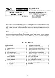
12.3 Outline diagram (unit:mm)<br />
20<br />
2-ø9<br />
72<br />
195<br />
312<br />
220<br />
Selector cock<br />
Provided when "D" is<br />
specified in 6th digit<br />
of PILC code.<br />
Not provided when "Y".<br />
3.2 95<br />
14 230<br />
ø15<br />
Cable gland<br />
For ø23.5/ø15.8 tube<br />
39<br />
5-G1/2<br />
40 40 40 40<br />
Connection diagram<br />
1<br />
2<br />
3<br />
4<br />
5<br />
6<br />
7<br />
8<br />
9<br />
10<br />
11 12 13 14<br />
N<br />
L<br />
Thermocouple<br />
signal<br />
Zirconia<br />
signal<br />
Analog<br />
output<br />
Alarm<br />
contact<br />
output<br />
signal<br />
Detector<br />
heater<br />
power<br />
supply<br />
Power<br />
supply<br />
Conditions of converter alarm contact output<br />
(between No.7 and No.8 terminals)<br />
The 5th digit of<br />
converter code<br />
symbols<br />
Power OFF<br />
Power ON,<br />
normal<br />
Power ON,<br />
alarm<br />
B Open Open Closed<br />
C Open Closed Open<br />
-22-