

ASPIRE Winter 10 - Aspire - The Concrete Bridge Magazine
ASPIRE Winter 10 - Aspire - The Concrete Bridge Magazine
ASPIRE Winter 10 - Aspire - The Concrete Bridge Magazine

Create successful ePaper yourself
Turn your PDF publications into a flip-book with our unique Google optimized e-Paper software.
1.<br />
2.<br />
3.<br />
<strong>The</strong> precaster’s recommendations during<br />
preliminary design included limiting the<br />
arch rib’s weight of each segment to<br />
140 kips. However, due to the amount<br />
of reinforcement required in the arch<br />
segments the weight reached 160 kips. To<br />
handle the arch-rib segments in the plant,<br />
the arch casting form was strategically<br />
positioned so two travel lifts could nest<br />
and lift in tandem.<br />
<strong>The</strong> precaster also worked with the<br />
reinforcing bar supplier to provide longer<br />
than typical length bars. This avoided<br />
the need to splice bars within the arch<br />
segments, which would have added time<br />
and complexity. Rather than the typical<br />
60-ft-long bars, the supplier fabricated<br />
70-ft-long pieces.<br />
Securing the longitudinal No. 14 reinforcement<br />
within the complex steel cage<br />
of reinforcing bars also posed a challenge.<br />
Typically, the stirrups would be tied into<br />
position and the No. 14 bars threaded<br />
through by hand. But the grid was too<br />
tight to allow that to be accomplished<br />
safely and efficiently. Instead, a woven<br />
tube that constricts as it’s pulled was<br />
placed over the end of each bar and then<br />
pulled through to the opposite end with<br />
a winch. This approach worked efficiently<br />
and provided better safety than working<br />
with the bars by hand.<br />
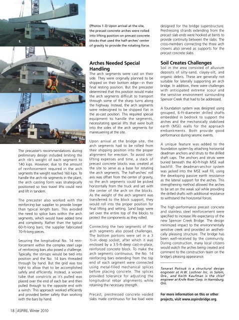
(Photos 1-3) Upon arrival at the site,<br />
the precast concrete arches were rolled<br />
into lifting position on precast concrete<br />
blocks that used the half-arches’ center<br />
of gravity to provide the rotating force.<br />
Arches Needed Special<br />
Handling<br />
<strong>The</strong> arch segments were cast on their<br />
side. <strong>The</strong>y were originally planned to be<br />
shipped on their bottom edge—in their<br />
final resting position. But the precaster<br />
determined that this position would make<br />
the arch segments difficult to transport<br />
through some of the sharp turns along<br />
the highway. Instead, the arch segments<br />
were redesigned to be shipped flat in<br />
the as-cast position. This required special<br />
equipment to handle the segments,<br />
necessitating special lifts that were built<br />
into the sides of the arch segments for<br />
maneuvering at the site.<br />
Upon arrival at the bridge site, the<br />
arch segments had to be rolled from<br />
their shipping position into the proper<br />
alignment for erection. To avoid sitelifting<br />
expenses and time, a stack of<br />
precast concrete blocks was created at<br />
the site to serve as a base for rotating<br />
the arch segments. <strong>The</strong> half-arches’ roll<br />
axis was offset from the center of gravity,<br />
so the arch segments could be picked<br />
horizontally from the truck and set with<br />
the center of the arch on the blocks.<br />
As the weight of the arch segment was<br />
transferred to the block support, they<br />
would roll into the proper position for<br />
final lifting and setting. Sand bags were<br />
set over the entire top of the blocks to<br />
protect the components as they rolled.<br />
Connecting the two segments of the<br />
arch segments also posed challenges.<br />
<strong>The</strong> bottom portions were set in a 3<br />
½-in.-deep socket, after which it was<br />
enclosed by a 3.5-ft-deep cast-in-place,<br />
reinforced concrete block. To make the<br />
arch segments continuous, the No. 14<br />
reinforcing bars extending from the top<br />
end of each segment were connected<br />
using metal-filled mechanical splices<br />
before placing concrete. <strong>The</strong> splices<br />
provided tolerance for adjusting the<br />
longitudinal rebar alignments while<br />
retaining the necessary strength.<br />
Precast, prestressed concrete voided<br />
slabs made continuous for live load were<br />
designed for the bridge superstructure.<br />
Prestressing strands extending from the<br />
precast slab ends were hooked at bents to<br />
provide continuity between the slabs. <strong>The</strong><br />
cross-members connecting the three arch<br />
crowns also served as supports for the<br />
precast concrete slabs.<br />
Soil Creates Challenges<br />
Soil in the area consisted of alluvium<br />
deposits of silty-sand, clayey-silt, and<br />
organic debris. <strong>The</strong>se are generally not<br />
suitable for laterally supporting an arch<br />
bridge. In addition, there were challenges<br />
with anticipated extreme scour and<br />
the sensitive environment surrounding<br />
Spencer Creek that had to be addressed.<br />
A foundation system was designed using<br />
grouped, 6-ft-diameter drilled shafts<br />
embedded in bedrock to support the<br />
arches and the mechanically stabilized<br />
earth (MSE) walls for the approach<br />
embankments. Both provide good<br />
performance during seismic events.<br />
A unique feature was added to the<br />
foundation system by attaching horizontal<br />
deadman anchors and struts to the drilled<br />
shaft caps. <strong>The</strong> anchors and struts were<br />
buried beneath the 40-ft-high MSE wall<br />
backfill. <strong>The</strong> deadman-anchor system<br />
was jacked into the MSE wall fill, using<br />
the developing passive earth resistance<br />
as the lateral support for the arches. This<br />
strengthening method allowed the arches<br />
to be set on the weak soil while providing<br />
the drilled shafts with additional resistance<br />
to withstand the horizontal forces.<br />
<strong>The</strong> high-performance precast concrete<br />
and stainless steel reinforcement were<br />
specified to increase life expectancy of the<br />
new Spencer Creek <strong>Bridge</strong>. <strong>The</strong> design<br />
minimized impact to the environmentally<br />
sensitive creek and provided an aesthetically<br />
pleasing structure. <strong>The</strong> bridge has<br />
been well-received by the community.<br />
During construction, many local citizens<br />
would watch the arches being created and<br />
comment to the construction team on the<br />
bridge’s pleasing appearance.<br />
____________<br />
Tanarat Potisuk is a structural design<br />
engineer at H.W. Lochner Inc. in Salem,<br />
Ore., and Keith Kaufman is the chief<br />
engineer at Knife River Corp. in Harrisburg,<br />
Ore.<br />
For more information on this or other<br />
projects, visit www.aspirebridge.org.<br />
18 | <strong>ASPIRE</strong>, <strong>Winter</strong> 20<strong>10</strong>


