herrenknecht ag softground tbms > 40 ft - SCATnow
herrenknecht ag softground tbms > 40 ft - SCATnow
herrenknecht ag softground tbms > 40 ft - SCATnow

Create successful ePaper yourself
Turn your PDF publications into a flip-book with our unique Google optimized e-Paper software.
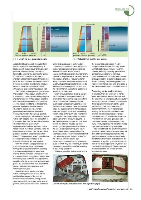
MIXSHIELDS<br />
xh<br />
Air pressure<br />
Air bubble<br />
Pb<br />
Pb<br />
Pw<br />
Pb<br />
h<br />
Air bubble pressure Pb<br />
Pb<br />
Slurry ( )<br />
h<br />
Slurry ( )<br />
Earth Water Slurry<br />
pressure pressure pressure<br />
Pb<br />
Fig 3: Mixshield face support principle<br />
area behind the pressure bulkhead or from<br />
inside the pressure chamber (figure 4). In<br />
locations with shallow cover and high water<br />
pressure, the level of slurry can only be<br />
lowered by a third of the diameter for access<br />
to the excavation chamber, in order to<br />
maintain sufficient safety <strong>ag</strong>ainst the risk of a<br />
blow out. In such cases, the required balance<br />
between excavation chamber and pressure<br />
chamber has to be controlled from the<br />
atmospheric area behind the pressure wall.<br />
The use of a submerged wall gate enables<br />
the isolation of the pressure chamber from<br />
the excavation chamber. By closing the gate,<br />
maintenance work in the pressure chamber<br />
can be carried out under reduced pressure<br />
or even free air conditions. In this scenario,<br />
pressure regulation of the excavation<br />
chamber is carried out via a remote<br />
pressurised bentonite tank air bubble,<br />
usually mounted on the back-up gantries.<br />
A new development for areas of sticky soil<br />
with a high clogging risk is the separation of<br />
the suction area from the rest of the pressure<br />
chamber. This was successfully<br />
implemented in the Mixshield used for the<br />
Weser tunnel, in northern Germany. Here, the<br />
invert area was isolated from the rest of the<br />
pressure chamber. Separate connection<br />
lines (or “compensation pipes”) provided the<br />
necessary pressure exchange to the<br />
excavation chamber for face support.<br />
With this system, a large percent<strong>ag</strong>e of<br />
the total flow volume can be circulated<br />
through the excavation chamber reducing<br />
the slurry density in specific areas and<br />
making it more constant. This results in less<br />
muck accumulation/clogging, as well as less<br />
secondary wear and more even operational<br />
conditions for the slurry circuit and treatment<br />
plant. The isolated suction area created still<br />
accommodates the rock crusher and<br />
submerged wall gate.<br />
Maintenance and service operations<br />
within working pressures of over 3.6 bar –<br />
and therefore outside of the normal<br />
framework of compressed air regulations –<br />
were successfully performed under special<br />
permits on the fourth Elbe tunnel and Weser<br />
Earth Water<br />
pressure pressure<br />
tunnel at air pressures of up to 4.5 bar.<br />
Professional divers can be employed for<br />
underwater operations or pressure levels<br />
beyond 3.6 bar for access into the<br />
suspension filled excavation chamber and/or<br />
for work to be performed in the invert area of<br />
the pressure chamber. Requirements for<br />
diving operations need to be established at<br />
an early st<strong>ag</strong>e of the project and have to be<br />
addressed in the design and installation of<br />
the TBM. Different applications also have to<br />
be defined. For example:<br />
Short-term, submerged dives to explore<br />
the tunnel face or to inspect cutter tools:<br />
Divers enter the bentonite suspension from<br />
the air bubble in the pressure chamber.<br />
Submerged wall doors are used to access<br />
the excavation chamber. These are located<br />
below the suspension level in the pressure<br />
chamber. This procedure was successfully<br />
implemented at the fourth Elbe River tunnel.<br />
Long-term, for major maintenance and<br />
repair work and/or pressures beyond 4.2<br />
bar: Special dive techniques, such as those<br />
used in the offshore industry are used<br />
(involving mixed gas or saturation diving). In<br />
the case of saturation diving, dive crews<br />
remain under pressurised conditions for<br />
extended periods. The divers are transferred<br />
from an above ground “living chamber” to<br />
the TBM via a mobile shuttle lock.<br />
Depending on their tasks and the pressure<br />
levels at which they are operating, the divers<br />
can work for several hours before returning<br />
to their “living chamber”.<br />
Whenever possible, maintenance work in<br />
Slurry<br />
pressure<br />
xh<br />
Fig 4: Reduced front level for face access<br />
Jaw crusher (le<strong>ft</strong>) and rotary sizer with <strong>ag</strong>itators (right)<br />
the pressurised area is done in a dry<br />
compressed air environment using masks<br />
for the breathing gas mixture. The entire<br />
process, including breathing gas mixtures,<br />
atmosphere, durations, or individual<br />
pressure levels, has to be precisely planned<br />
and supervised by experienced specialists.<br />
Saturation diving for tunnelling operations<br />
was used for the first time on a large scale at<br />
the Westershelde project, in the Netherlands.<br />
Crushing rocks and boulders<br />
In principle, there are two ways to handle<br />
rocks and boulders. Firstly, if the matrix of<br />
the tunnel face is strong enough, disc cutters<br />
excavate rocks and boulders. In most cases,<br />
this excavation mechanism can be used<br />
successfully down to boulder sizes of<br />
<strong>40</strong>0mm to 600mm. The remaining rock<br />
entering the excavation chamber is then<br />
crushed into smaller particles by a rock<br />
crusher located in the invert of the machine.<br />
The maximum allowable grain size a<strong>ft</strong>er<br />
crushing is dictated by the design of the<br />
slurry circuit, especially the size of discharge<br />
pipe, pump type and slurry flow speed.<br />
As a rule of thumb the practical maximum<br />
grain size can be considered to be about 30-<br />
<strong>40</strong>% of the discharge pipe diameter. The<br />
typical arrangement in the suction area for<br />
conditions with boulders and cobbles is the<br />
installation of a grill for grain size limitation in<br />
front of the suction pipe and a hydraulic jaw<br />
crusher in front of the grill. Different size jaw<br />
crusher capacities are used in different<br />
machine diameters:<br />
MAY 2008 Tunnels & Tunnelling International 39