herrenknecht ag softground tbms > 40 ft - SCATnow
herrenknecht ag softground tbms > 40 ft - SCATnow
herrenknecht ag softground tbms > 40 ft - SCATnow

Create successful ePaper yourself
Turn your PDF publications into a flip-book with our unique Google optimized e-Paper software.
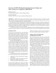
Figure 2.<br />
Figure 3.<br />
World’s largest Mixshield Ø15.4 m for Shanghai.<br />
Changjian under River Tunnels, Shanghai.<br />
expected geology are local intercalations of silty and<br />
sandy layers and shell residues.<br />
Due to a ground-water level of up to 47 m above<br />
the centre of the tunnel, the TBMs are designed for a<br />
maximum working pressure of 6.5 bar. At the deepest<br />
point the tunnel will run about 65 m below the<br />
surface.<br />
The tunnel lining consists of precast reinforced concrete<br />
segments with an inside diameter of 13.7 m. One<br />
tunnel ring consists of 9 + 1 segments and has a length<br />
of 2 m. For both tunnels altogether 7,500 segment rings<br />
are needed. They will be delivered with two special<br />
trucks from the segment fabrication yard, which is<br />
about 1.5 km away, to the jobsite.<br />
A feature of the cutting wheel design are six accessible<br />
main spokes, which are sealed <strong>ag</strong>ainst the water<br />
pressure.To avoid adhesion of sticky clay at the cutting<br />
wheel, the centre area is equipped with an own slurry<br />
circuit. Large openings in the cutting wheel optimise<br />
the flow of material and reduce the risk of block<strong>ag</strong>e of<br />
material in the centre.<br />
In order to get reliable information about the condition<br />
of the so<strong>ft</strong> ground tools and buckets, especially<br />
in the loaded outer area of the cutting wheel, ten cutting<br />
tools (2 buckets and eight so<strong>ft</strong> ground tools) are<br />
equipped with an electronic wear detection system.<br />
The system generates online data on the state of<br />
the selected cutting tools and gives early warning of<br />
possible wear to the TBM staff.<br />
With this electronic wear detection system maintenance<br />
works can be planned and the service life of<br />
the tools can be optimised, thereby minimising costly<br />
chamber accesses under compressed air.<br />
The heart of the system is a new tool support with<br />
integrated sender electronics.This is permanently connected<br />
to the so<strong>ft</strong> ground tool through induction loops<br />
and “detects” whether the wear limit is reached. For<br />
this purpose the sender is electrically connected with<br />
a power supply. If the probe is intact a certain current<br />
flows but if the probe is destroyed due to wear of the<br />
tool this is “sensed” by the sender through a significantly<br />
higher fault current. The sender is inductively<br />
connected with the receiver and the tool probe through<br />
a small gap. A LED informs the machine driver of the<br />
wear. With this automatic method of wear detection<br />
unnecessary maintenance could be avoided.<br />
The design of the cutting wheel was conceived in<br />
order to allow man access to its interior space under<br />
atmospheric air pressure, sealed from the ground water<br />
pressure outside.<br />
Tool change devices, which are integrated in the cutting<br />
wheel, allow the personnel to replace tools under<br />
atmospheric conditions from the interior of the cutting<br />
wheel.<br />
The tool change device has two functions:<br />
1 To serve as receptacle for the tools.<br />
2 To allow the outward and inward airlock transit of<br />
the tools.<br />
In order to flush the devices there are flushing<br />
connections installed on the rear case.<br />
This tool change device consists of the following<br />
main components:<br />
1 Front casing. This forms the connection to the steel<br />
structure of the cutterhead and is circumferentially<br />
welded to it.<br />
2 Rear casing. It is flange-mounted to the front casing<br />
and assumes in connection with the front casing the<br />
guidance of the slider and of the sliding pipe.<br />
3 Slider.<br />
4 Sliding pipe. The sliding pipe receives the cutting<br />
tool.<br />
The sliders are opened in the working position. In<br />
this position the cutting wheel is made water tight by<br />
the front seal. In case of dam<strong>ag</strong>e of this seal, the circumferential<br />
profile seal located around the slider and<br />
the rear seal would assure the leak tightness.<br />
A further feature, which has to be mentioned, is<br />
the installation of road elements by the back-up of the<br />
Mixshield. The back-up is composed of three trailers.<br />
The first one contains all necessary equipment and<br />
supply material for the functioning of the excavation<br />
1172