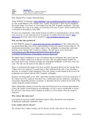
MIXSHIELDS Excavation chamber Pressure chamber 1 1 15% 15% 15% 15% 1 2 Flushing excavation chamber crown Flushing centre cutting wheel Flushing excavation chamber invert Flushing stone crusher 1 50% 50% 5 4 20% 5 <strong>40</strong>% 3 3 50% <strong>40</strong>% 10% <strong>40</strong>% 10% 20% 3 4 5 Bentonite nozzles 10% 10% Bentonite distribution 60% <strong>40</strong>% Infront behind the submerged wall Above: Fig 7 - Example of suspension supply to excavation and pressure chamber Le<strong>ft</strong>: 17” monobloc cutter, on the ESCSO Project in Portland, USA • 4m-6.5m: max boulder size 500mm • 6m-10m: max boulder size 800mm • 9m: max boulder size 1200mm Early attempts to use “in-line” crushers or boulder traps in the discharge pipe were unsuccessful and have therefore nearly disappeared from modern designs. The amount, size and consistency of the anticipated rock influences the choice of cutterhead configuration and cutter tools. Disc cutters are the most effective tools for excavating hard rock. However, the cutting tools for handling rocks and boulders with a Mixshield require different features in order to operate under pressurised slurry conditions. In particular, the cutter seal and seal gap design differs, to effectively prevent the penetration of muck and slurry (mud packing), but also provide the least possible friction to ensure the cutters are rolling properly across the tunnel face. For face pressures above 4 bar, compensating disc cutter systems have been developed that can handle high outside pressures as well as significant pressure variations, which on a 12m slurry machine is in the range of 1.5 bar from crown to invert. If rolling is restricted due to inner friction, or the cutter is jammed, it will no longer be available for regular excavation and will only grind on one side. Two-ring cutters provide a better performance at lower single-ring thrust capacity, as they enable several cutting or face contact patterns for the same number of bearing seals and therefore a better relationship between cutting ring- and inner friction. The use of two-ring cutters also requires fewer housing positions on the cutterhead and, for this reason, provides more options for cutterhead openings to REFERENCES 1. B Maidl, M Herrenknecht & L Anheuser, 1996. “Mechanised Shield Tunnelling” Ernst & Sohn 2. W Burger, 2007. “Design Principles For So<strong>ft</strong> Ground Cutterheads” Proc. RETC 2007, Toronto 3. W Burger, 2006. “Hard Rock Cutterhead Design” Proc. NAT 2006, Chic<strong>ag</strong>o optimise muck flow. In many cases, the use of two-ring cutters in the inner face and centre area and singlering cutters for outer face and periphery area is a good compromise. Grain size limiters in the muck openings are installed to keep loose rock or large boulders at the tunnel face, so they can be broken down by the cutters. The design and layout of the size limiters has to be decided on the basis of anticipated ground conditions and installed crusher capacity. Special care also has to be given to the working levels of the different tool types on a mixed face cutterhead. Disk cutters should be positioned 30mm to 50mm ahead of the so<strong>ft</strong> ground tools to ensure that hard rock or boulders are first attacked by the appropriate tool type. Positive results have been achieved on several mixed face slurry machines using specially designed Monoblock cutters, with a reduced risk of secondary wear to noncutting related elements of the cutters, such as split rings or hubs. The combination of mixed face cutterhead tool arrangements and jaw crusher-suction grill arrangements has proven effective when dealing with variable face conditions or cobbles and boulders. The need to manually intervene in order to remove or split boulders has been reduced dramatically and can be considered an exception these days. Clogging risks The problem of clogging can be addressed in several ways: choice of tools, quantity of fresh suspension supply, flushing and/or <strong>ag</strong>itation systems in the excavation chamber, flow in the chamber and the geometrical design and shape of cutterhead, excavation and pressure chamber. The preferred method in adhesive ground conditions is the use of wide cutting tools, in order to achieve bigger cuttings or clay chips. This also reduces the number of tools required to cover the full face. The use of fewer cutting tools increases the free areas between the individual tool sockets and therefore reduces the risk of “bridge building” and adhesion at the cutterhead. A high circulation or flushing quantity in the excavation chamber, in combination with a suitable cutterhead design, encour<strong>ag</strong>es free flow of excavated muck and reduces the time cuttings remain in the chamber to a minimum. Optimisation of the flow and a reduction in the time taken for muck to pass through the excavation chamber also have positive effects on wear reduction. This was demonstrated on the CTRL’s Thames Tunnel drives, in London, where two Mixshields were used to mine through chalk layers containing a large amount of abrasive flint. Flushing nozzles at the centre of the cutterhead supply fresh suspension close to the tunnel face where the soil excavation takes place. These feed lines in the rotating cutterhead are supplied via single or multiple channel rotary joints in the cutterhead centre. Feed line outlet arrangements in front of the submerged wall ensure a sufficient quantity of supply to the rear face of the cutterhead in the excavation chamber. For Mixshields operating in adhesive ground, there is a general tendency to feed fresh suspension in front of the submerged wall. Each individual supply line into the excavation chamber or the cutterhead can be controlled from the TBM’s cabin, with information about the flow and pressure of each individual line being fed back to the operator. Depending on the ground and the direction of cutterhead rotation, adaptation and optimisation of the feed-line flushing pattern is also possible. The installation of mixing arms behind the cutterhead is also a common solution to assist flushing. There are two ways to avoid adhesion or muck settlement in the pressure chamber area. Mechanical <strong>ag</strong>itator wheels in the invert area can assist muck flow. Alternatively, rotary sizers (see p39) can be used to cut clay chips to size, while not obscuring continuous conveying into the suction pipe. Additional flushing nozzles in the pressure chamber can also assist flow. T&T Part 2 of this article, due to be published next month, will focus on potential future developments of Mixshield technology. <strong>40</strong> Tunnels & Tunnelling International MAY 2008
REFERENCE PAPER: LIFTING THE LID ON MIXSHIELD PERFORMANCE.