Development of Circularly Polarized Microstrip ... - CEReS - åè大å¦
Development of Circularly Polarized Microstrip ... - CEReS - åè大å¦
Development of Circularly Polarized Microstrip ... - CEReS - åè大å¦

You also want an ePaper? Increase the reach of your titles
YUMPU automatically turns print PDFs into web optimized ePapers that Google loves.
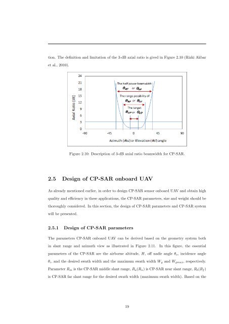
tion. The definition and limitation <strong>of</strong> the 3-dB axial ratio is gived in Figure 2.10 (Rizki Akbar<br />
et al., 2010).<br />
Figure 2.10: Description <strong>of</strong> 3-dB axial ratio beamwidth for CP-SAR.<br />
2.5 Design <strong>of</strong> CP-SAR onboard UAV<br />
As already mentioned earlier, in order to design CP-SAR sensor onboard UAV and obtain high<br />
quality and efficiency in these applications, the CP-SAR parameters, size and weight should be<br />
thoroughly considered. In this section, the design <strong>of</strong> CP-SAR parameters and CP-SAR system<br />
will be presented.<br />
2.5.1 Design <strong>of</strong> CP-SAR parameters<br />
The parameters CP-SAR onboard UAV can be derived based on the geometry system both<br />
in slant range and azimuth view as illustrated in Figure 2.11.<br />
In this figure, the essential<br />
parameters <strong>of</strong> the CP-SAR are the airborne altitude, H, <strong>of</strong>f nadir angle θ o , incidence angle<br />
θ i , and the desired swath width and the maximum swath width W g and W gmax , respectively.<br />
Parameter R m is the CP-SAR middle slant range, R a (R n ) is CP-SAR near slant range, R b (R f )<br />
is CP-SAR far slant range for the desired swath width (maximum swath width). Based on the<br />
19