Development of Circularly Polarized Microstrip ... - CEReS - åè大å¦
Development of Circularly Polarized Microstrip ... - CEReS - åè大å¦
Development of Circularly Polarized Microstrip ... - CEReS - åè大å¦

Create successful ePaper yourself
Turn your PDF publications into a flip-book with our unique Google optimized e-Paper software.
equired (Tamakuma and Iwasak, 2003 and James and Hall, 1989). <strong>Microstrip</strong> antenna on its<br />
own doesnt generate circular polarization; subsequently, some changes should be done to the<br />
patch antenna to be able to generate the circular polarization (Suzuki et al., 1987). The most<br />
commonly used feeding techniques in circular polarization generation are dual feed and single<br />
feed. However, with some phase adjustment, the multiple feed also can be employed to generate<br />
the circular polarization antenna (Yohandri et al., 2012).<br />
3.3.1 Dual feed circularly polarized microstrip antenna<br />
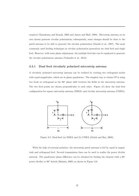
A circularly polarized microstrip antenna can be realized by exciting two orthogonal modes<br />
with equal magnitudes, which are in phase quadrature. The simplest way to obtain CP is using<br />
two feeds at orthogonal as the 90 o phase shift between the fields in the microstrip antenna.<br />
The two feed points are chosen perpendicular to each other. Figure 3.5 show the dual feed<br />
configuration for square microstrip antenna (SMSA) and circular microstrip antenna (CMSA).<br />
Figure 3.5: Dual-feed (a) SMSA and (b) CMSA (Girish and Ray, 2003).<br />
With the help <strong>of</strong> external polarizer, the microstrip patch antenna is fed by equal in magnitude<br />
and orthogonal feed. Several transmission lines can be used to realize the power divider<br />
network. The quadrature phase difference can be obtained by feeding the element with a 90 o<br />
power divider or 90 o hybrid (Balanis, 2005) as shown in Figure 3.6.<br />
37