Eurotubi Pressfitting System - Technical Guide ... - Damstahl
Eurotubi Pressfitting System - Technical Guide ... - Damstahl
Eurotubi Pressfitting System - Technical Guide ... - Damstahl

You also want an ePaper? Increase the reach of your titles
YUMPU automatically turns print PDFs into web optimized ePapers that Google loves.
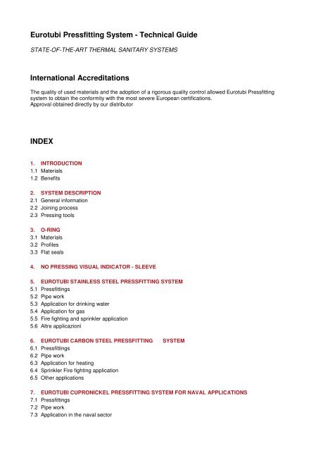
<strong>Eurotubi</strong> <strong>Pressfitting</strong> <strong>System</strong> - <strong>Technical</strong> <strong>Guide</strong><br />
STATE-OF-THE-ART THERMAL SANITARY SYSTEMS<br />
International Accreditations<br />
The quality of used materials and the adoption of a rigorous quality control allowed <strong>Eurotubi</strong> <strong>Pressfitting</strong><br />
system to obtain the conformity with the most severe European certifications.<br />
Approval obtained directly by our distributor<br />
INDEX<br />
1. INTRODUCTION<br />
1.1 Materials<br />
1.2 Benefits<br />
2. SYSTEM DESCRIPTION<br />
2.1 General information<br />
2.2 Joining process<br />
2.3 Pressing tools<br />
3. O-RING<br />
3.1 Materials<br />
3.2 Profiles<br />
3.3 Flat seals<br />
4. NO PRESSING VISUAL INDICATOR - SLEEVE<br />
5. EUROTUBI STAINLESS STEEL PRESSFITTING SYSTEM<br />
5.1 <strong>Pressfitting</strong>s<br />
5.2 Pipe work<br />
5.3 Application for drinking water<br />
5.4 Application for gas<br />
5.5 Fire fighting and sprinkler application<br />
5.6 Altre applicazioni<br />
6. EUROTUBI CARBON STEEL PRESSFITTING SYSTEM<br />
6.1 <strong>Pressfitting</strong>s<br />
6.2 Pipe work<br />
6.3 Application for heating<br />
6.4 Sprinkler Fire fighting application<br />
6.5 Other applications<br />
7. EUROTUBI CUPRONICKEL PRESSFITTING SYSTEM FOR NAVAL APPLICATIONS<br />
7.1 <strong>Pressfitting</strong>s<br />
7.2 Pipe work<br />
7.3 Application in the naval sector
8. GENERAL USE TECHNIQUES<br />
8.1 Pipe laying and expansion<br />
8.2 Expansion room<br />
8.3 Expansion compensators<br />
8.4 Pipe fixing<br />
8.5 Sprinkler fire fighting application<br />
9. INSTALLATION INSTRUCTIONS<br />
9.1 Transport, storage and withdrawal<br />
9.2 Pipe cutting<br />
9.3 Pipe-end deburring<br />
9.4 Checking the presence and positioning of o-rings<br />
9.5 Inserting pipes in fittings and marking the correct position<br />
9.6 Use of assembly clamps for “Big Size” diameters<br />
9.7 Pressing tool assembly<br />
9.8 Pressing<br />
10. CORROSION RESISTANCE<br />
10.1 Stainless steel installations for drinking water<br />
10.2 Stainless steel installations for gas, fire fighting and other applications<br />
10.3 Carbon steel installations for heating<br />
10.4 Carbon steel installations for sprinkler fire fighting and other applications<br />
11. SYSTEM COMMISSIONING<br />
11.1 Testing<br />
11.1.1 Drinking water system<br />
11.1.2 Heating system<br />
11.1.3 Gas system<br />
11.2 Washing the pipes<br />
11.3 Disinfection<br />
11.4 Noise insulation<br />
11.5 Thermal insulation<br />
11.6 Protection against freezing<br />
12. PIPE CALCULATION<br />
12.1 Pressure drops<br />
12.2 Pressure drops of a straight pipe<br />
12.3 Pressure drops of single localized resistances<br />
13. COUPLING FITTINGS TABLE<br />
14. CHEMICAL COMPATIBILITY OF EUROTUBI PRESSFITTING SYSTEMS<br />
15. POSSIBLE CAUSES OF LEAKS<br />
16. GUARANTEE<br />
17. FAQ - FREQUENTLY ASKED QUESTIONS<br />
ANNEXES
1. INTRODUCTION<br />
The <strong>Eurotubi</strong> <strong>Pressfitting</strong> <strong>System</strong> is an extremely fast and simple pressfitting assembly system, producing<br />
reliable joints with high mechanical resistance, for civil, industrial, naval and fire fighting pipework system<br />
installations.<br />
The diameters currently available range from 12 to 108 mm, depending on the material used. The three<br />
greater diameters of 76.1, 88.9 and 108 mm are commonly called “big size”.<br />
The design and commissioning of these distribution networks require a vast knowledge of technical notions<br />
and local regulations and legislation, potentially varying from country to country. This <strong>Technical</strong> <strong>Guide</strong><br />
provides basic information to:<br />
- assess the fields of application with due skill;<br />
- design the systems according to the latest technological criteria;<br />
- perform the installations up to standard.<br />
In any case it is the task of the designer and/or the installer to ensure that the standards contained in this<br />
<strong>Guide</strong> are compatible with the local applicable laws. Otherwise, the local applicable laws prevail and<br />
therefore it is not possible to use <strong>Eurotubi</strong> <strong>Pressfitting</strong> <strong>System</strong>.<br />
1.1 Materials<br />
Depending on the application, the following materials are used:<br />
- stainless steel;<br />
- carbon steel;<br />
- cupronickel.<br />
1.2 Benefits<br />
The main benefits of the <strong>Eurotubi</strong> <strong>Pressfitting</strong> <strong>System</strong> are:<br />
- alternative practice to traditional joining methods that require welding and/or threading;<br />
- overall system cost saving;<br />
- fast and easy assembly;<br />
- clean and safe system, with no risk for the installer;<br />
- reliable, secure and long-lasting seals;<br />
- minimal possibility of errors by operators;<br />
- no use of heat sources;<br />
- no fire risk during installation;<br />
- high corrosion resistance;<br />
- high thermal resistance;<br />
- weight significantly reduced compared to traditional metal systems;<br />
- high visual appeal, ideal for visible installations;<br />
- exceptional fluid flowing properties;<br />
- the end quality depends on the equipment rather than on the skill of the operator, who does not need to be<br />
highly qualified.
2. SYSTEM DESCRIPTION<br />
2.1 General information<br />
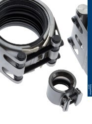
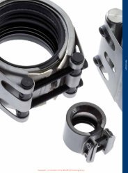
The following components make up the <strong>Eurotubi</strong> <strong>Pressfitting</strong> <strong>System</strong>:<br />
<strong>Pressfitting</strong>s<br />
The basic system component. At each end arranged for the pressing there is a shaped seat, which holds a<br />
synthetic rubber o-ring seal.<br />
They are available in various types and figures, including some of various materials, which can be used for<br />
flanged and threaded connections or welded joints.<br />
Pipe work<br />
The second system component. Supplied by <strong>Eurotubi</strong> Europa. Commercially available pipes may also be<br />
used, provided they comply to the technical specifications set out in sections 5, 6 and 7 of this manual,<br />
detailing the various applications.<br />
Pressing tools<br />
Used to join the two components, these also are supplied by <strong>Eurotubi</strong> Europa. Commercially available tools<br />
may also be used, provided they comply to the requirements set out at point 2.3 of this manual.<br />
2.2 Joining process<br />
Pressfitted pipe joints are fast, easy and risk-free. The result of the operation is “definitive”, since it is no<br />
longer possible to separate the components and return to the original condition.<br />
The pipe is inserted into the fitting, up to the stop, then the jaw attachments of the pressing tool press the<br />
shaped end of the fitting onto the pipe.<br />
Pressing produces two deformations. The first, radial deformation, compresses the o-ring in the shaped<br />
chamber and guarantees that the pipe is hermetically sealed. The second, geometric deformation of both<br />
fitting and pipe, creates a mechanical joint, resistant to slipping and rotation.<br />
The resulting polygonal pressing profile varies according to the diameter, being hexagonal or similar to a<br />
triangular shape, but in any case creating a homogenous joint.<br />
Fig. 1 shows examples of the components, in profile and section views, before and after pressing.<br />
Joints produced in this way are extremely strong, but flexible enough to withstand the stresses resulting from<br />
initial installation and those, such as vibrations and thermal expansion etc., that occur in normal operating<br />
conditions. This is provided that installation has been carried out according to the instructions in section 9 of<br />
this manual.<br />
2.3 Pressing tools<br />
The pressing process is achieved using pressing tools equipped with interchangeable press heads (jaws or<br />
chains) that vary according to the fitting and pipe diameters.
Various types of electromechanical and more frequently electrohydraulic pressing tools are commercially<br />
available in the different battery or mains-powered (220V – 110V – 48V) versions. Usually they are divided<br />
into 3 classes, depending on the maximum force applicable:<br />
- portable with low force (up to 17KN), able to press approximately up to a diameter of 28 mm;<br />
- medium force (up to 40 KN); they are the most common and versatile and are able to press up to a<br />
diameter of 54 mm;<br />
- high force (more than 40 KN), suitable to press “big size” diameters (starting from a diameter of 76.1 mm).<br />
They are of significant size and weight.<br />
The <strong>Eurotubi</strong> <strong>Pressfitting</strong> <strong>System</strong> can be used with a wide variety of pressing tools, provided that these are<br />
equipped with “M” profile terminals.<br />
Tab. 1 below lists the three main manufacturers commercially available that <strong>Eurotubi</strong> constantly tests with its<br />
products, as well as the related ranges compatible with <strong>Eurotubi</strong> <strong>Pressfitting</strong> <strong>System</strong>.<br />
There are other manufacturers, some reliable, especially with the latest models. Since it is not possible to<br />
guarantee beforehand the compatibility with all the tools commercially available, users are invited to contact<br />
the <strong>Eurotubi</strong> <strong>Technical</strong> Department to have instructions on this point.<br />
We recommend:<br />
- following the use and maintenance methods set by the manufacturer closely;<br />
- regularly checking the working surfaces of the jaws;<br />
- frequently cleaning the jaws with a degreaser;<br />
- keeping it correctly lubricated;<br />
- when the tools have worn out, dispose of all the components, especially the batteries, according to the<br />
requirements indicated by the related regulations.<br />
No claim will be accepted, unless the compliance with the maintenance/revision programme specified by the<br />
manufacturers is documented.<br />
The use of jaws and chain with a V profile or declared valid for both profiles is absolutely not tolerated for<br />
any diameter.<br />
Note. In practice pressing terminal sets and pressing tools from different manufacturers are often used. The<br />
combination of possible couplings is so broad that it is not possible to provide any guarantee.<br />
3. O-RING<br />
Made of synthetic rubber they guarantee that a joint is hermetically sealed. The diameters currently available<br />
range from 12 to 108 mm, depending on the material used.<br />
3.1 Materials<br />
Depending on the application, o-rings with the following materials are used:
EPDM - black (commonly associated to WATER)<br />
The standard material, available in diameters from 12 to 108 mm, suitable for temperatures between -20 and<br />
+120 °C and for pressures up to a maximum of 16 bar.<br />
It has a host of applications and is used for drinking water, heating, cooling, steam, fire fighting, compressed<br />
air (oil free) and inert gas systems.<br />
HNBR - yellow (commonly associated to GAS)<br />
This material is used in gas systems. It is available in diameters from 15 to 108 mm and is suitable for<br />
temperatures between -20 and +70 °C and for pressures up to a maximum of 5 bar.<br />
FPM – green, coinciding with FKM – green (commonly associated to SOLAR)<br />
This material is used for particularly testing conditions, with temperatures between -20 and + 180 °C and for<br />
pressures up to a maximum of 16 bar. It is available in diameters from 12 to 108 mm and is particularly<br />
suitable for solar systems. Whereas it is not recommended for systems with the presence of steam.<br />
FPM – red, coinciding with FKM – red (commonly associated to INDUSTRIAL)<br />
This material is used for some special applications, with temperatures between -20 and + 180 °C and for<br />
pressures up to a maximum of 16 bar. It is available in diameters from 12 to 108 mm and is used for<br />
industrial applications, such as for example the transportation of different types of fluids, such as lubricant<br />
and cutting oils, gas oil, etc. and for compressed air systems (with oil). Whereas its use is not recommended<br />
for systems with the presence of steam.<br />
Note. Given that the green and red FPM materials basically have identical features, in the near future<br />
<strong>Eurotubi</strong> intends to offer a single solution in blue FPM, outperforming the current ones.<br />
To fully understand the compatibility of the seals with the various types of fluids, it is worth referring to<br />
section 14 below.<br />
The characteristics and the applications of the different o-rings are reported in Tab. 2.<br />
Note. In the presence of industrial applications and special systems, it is necessary to consult the <strong>Eurotubi</strong><br />
<strong>Technical</strong> Department, providing indications on the temperature conditions and pressure and on the exact<br />
chemical composition of the convoyed component.<br />
Note. In no case will commercially available o-rings assembled into <strong>Eurotubi</strong> joints be accepted.<br />
3.2 Profiles<br />
The o-ring seals have a double configuration.<br />
Standard (fig. 2)<br />
The traditional o-ring, which guarantees that a pipe is hermetically sealed. It is available in all the elastomer<br />
versions and used for all applications.<br />
Leak-path / LBP (fig. 3)
A patented innovatively designed o-ring which is only available in the EPDM version and for diameters from<br />
12 to 54 mm. It has a polygonal shape, including a succession of tubular sections with rectilinear axis and<br />
constant section, arranged as a ring to generate a multitude of flows between the non deformed o-ring and<br />
its seat. If the fitting is inadvertently not pressed, the profile of the o-ring identifies the anomalous condition,<br />
both during the seal test and visually, through leaking of water in the form of dripping, in compliance with the<br />
Work Sheet DVGW W 534. This characteristic is commonly known as “Leak Before Press – L.B.P.” .<br />
Otherwise, after the fitting has been pressed, the o-ring easily fills all the flows, ensuring the<br />
hermetic seal as with the traditional type.<br />
Various similar solutions are commercially available, which focus on obtaining the same result described<br />
above. In comparison to these, the solution conceived by <strong>Eurotubi</strong> has the following benefits:<br />
- its shape is closer to the traditional o-ring as it is the only seal with a constant circular section, along its<br />
entire length;<br />
- you do not run the risk of leaks occurring after pressing, as happens in other systems when, due to the o-<br />
ring’s profile, the rubber area with large deformations coincides with the metallic area slightly deformed by<br />
the pressing, thus not managing to hermetically seal all the potential flowpaths, especially during thermal<br />
variations.<br />
Note. For diameters greater than 54 mm, or the three big sizes, the “leak-path” function is guaranteed by the<br />
use of the standard o-ring, which was also approved in compliance with Work Sheet DVGW 534.<br />
3.3 Flat seals<br />
They are assembled in the “orifices with swivel” figures, used when it is necessary to temporary split a<br />
section of the system.<br />
Since repeating this operation may cause a deterioration of the seal, the seal needs to be replaced during<br />
each intervention.<br />
Also the flat seals are available in all the elastomer materials and are used for all applications, according to<br />
the same criteria shown in Tab. 2 for the o-rings.<br />
4. NO PRESSING VISUAL INDICATOR - SLEEVE<br />
In a new pressfitting system, any leaks are attributable to just one reason: the incorrect or failed pressing of<br />
the joints.<br />
With a completed system, during testing, the check of all the joints may be rather difficult, since the fitting<br />
installed, but unpressed, in any case offers a certain seal and the leak may be almost undetectable (situation<br />
regarding the standard o-ring).<br />
In addition to using the ”leak-path o-ring” (described under point 3.2 of this <strong>Technical</strong> <strong>Guide</strong>), <strong>Eurotubi</strong><br />
provides installers with an additional solution that is useful to prevent or in any case easily identify any<br />
unpressed joint.
It is a visual system called “press-check sleeve”: a thin and eye-catching coloured film applied externally to<br />
the joints, conformed to the o-ring housing.<br />
This film does not compromise or interfere in any way with the assembly. When the fitting is pressed, the film<br />
tears and detaches from the metal, assuming a fractured appearance and providing easy manual removal<br />
without using any tools (fig. 4-5).<br />
When checking the system, the installer will quickly notice, even from meters away, if any coloured film has<br />
remained intact on the joints (fig. 6). If removing the film after pressing was forgotten, during the visual check<br />
the installer will in any case notice a very different look from the original one. Therefore it will not be<br />
necessary to get physically close to all the joints to examine each press joint and identify any slight drip. If<br />
the pressing can not be seen but only touched (in hidden or dark areas), the condition of the film can be<br />
easily checked also just by touching it.<br />
The colour of the film is associated to the different type of joints: blue for joints of the stainless steel–water<br />
range, yellow for joints of the stainless steel–gas range, red for joints of the carbon steel range (fig. 7).<br />
The “sleeve” indicator is applicable to all the joints for diameters from 12 to 54 mm. For the big sizes it is<br />
considered rather superfluous, given that the dimension of the joints allows a quick visual check of the<br />
pressings also from a distance.<br />
This solution, combined with the presence of the ”leak-path o-ring” represents double safety for the installer<br />
(fig. 8).<br />
Note. The press-check sleeve was purposefully designed to remain torn on the fitting in a way to not deposit<br />
inside the pressing jaws. In case film residues remain in the pressing jaws, we recommend removing them<br />
prior to proceeding to a new joint operation.<br />
5. EUROTUBI STAINLESS STEEL PRESSFITTING SYSTEM<br />
5.1 <strong>Pressfitting</strong>s<br />
The pressfittings are made of austenitic stainless Cr-Ni-Mo steel n. 1.4404 (AISI 316L). The diameter ranges<br />
from 15 to 108 mm. Under development are the diameters 12 and 64 mm.<br />
The types available are listed in the catalogue and the dimension they are identified with corresponds to the<br />
external diameter of the pipe on which they are pressed.<br />
The special process used to make the pressfittings can be broken down into the following main stages:<br />
- cutting the pipe into sections and mechanical working;<br />
- bending or any other working;<br />
- cold forming of the o-ring seat;<br />
- any welding of other parts of the fitting;<br />
- heat treatment in a controlled atmosphere at 1050°C, to restore the material’s original characteristics and<br />
increase the resistance to corrosion.
All the processes are controlled through the operating methods set by standard UNI EN ISO 9001 and are<br />
submitted to continuous audits by the authorities that have approved them for the various applications, in<br />
compliance with the related technical specifications for drinking water (DVGW W 534), gas (DVGW VP 614),<br />
fire fighting (VdS 2344/2100-26), marine (RINA), and various European accreditations (SITAC, CSTB, etc.).<br />
All the pressfittings with a shaped press end are identified with a permanent marking, which refers to the<br />
certifications obtained.<br />
5.2 Pipe work<br />
Pipes used in mains systems are made of austenitic stainless Cr-Ni-Mo steel n. 1.4404 (AISI 316L),<br />
according to Standards UNI EN 10088-2, UNI EN 10217-7 and UNI EN 10312. Generally they are<br />
commercially available and sold in 6-metre lengths.<br />
The pipes provided by <strong>Eurotubi</strong> Europa comply to the accreditations obtained and in particular to the<br />
technical specifications DVGW W 541 and VdS. Therefore they are marked with the respective DVGW and<br />
VdS markings, followed by approval numbers and may be used for all the applications.<br />
If of the commercially available type, the pipes must bear the DVGW marking followed by the approval<br />
number and may be used for all applications, except for the sprinkler fire fighting application, for which the<br />
use of pipes approved by <strong>Eurotubi</strong> is imperative.<br />
The technical characteristics of the pipes are reported in Tab. 3.<br />
5.3 Application for drinking water<br />
The stainless steel <strong>Eurotubi</strong> <strong>Pressfitting</strong> <strong>System</strong> is the ideal solution for the creation of systems used to<br />
distribute drinking water, since stainless steel AISI 316L guarantees the utmost hygiene and significant<br />
resistance to corrosion.<br />
The o-ring seals, made of black EPDM are resistant to aging, heat and chemical additives and are therefore<br />
particularly suitable for all types of treated water. It is available in the “standard” and “leak-path” versions. In<br />
addition it also meets all the hygienic requirements, in compliance with technical specification DVGW W 270<br />
and Ministerial Decree 174/2004.<br />
Conditions of use<br />
- Maximum pressure: 16 bar<br />
- Maximum related depression: - 0.8 bar (absolute pressure: 0.2 bar)<br />
- Maximum temperature: 120 °C<br />
Certifications<br />
<strong>Eurotubi</strong> pressfittings have been certified for drinking water use by a great many national and international<br />
authorities. Notably, it far exceeds the demanding quality requirements of the German Standard DVGW<br />
W534.<br />
Note. In this application it is absolutely forbidden to use o-rings in HNBR and FPM as these are not<br />
approved for carrying drinking water.
Note. The market has been recently offering the use of ferritic stainless steel pipe work in place of that made<br />
of austenitic steel. <strong>Eurotubi</strong> provides pipes made of ferritic Cr-Mo-Ti (without nickel) stainless steel, approved<br />
according to German technical specification DVGW W 541.<br />
5.4 Application for gas<br />
The <strong>Eurotubi</strong> <strong>Pressfitting</strong> <strong>System</strong> is approved in several European countries for use in gas distribution<br />
systems, with external aboveground pipes, running inside or outside buildings. It can be used for all types of<br />
combustible gas, both natural and liquid, in the reference standard DVGW G 260.<br />
The o-ring seals are made of yellow HNBR and as such, are compatible with any of the gas varieties used<br />
and are resistant to aging.<br />
Conditions of use<br />
- Maximum pressure: 5 bar<br />
- Minimum temperature: -20 °C<br />
- Maximum temperature: 70 °C<br />
Certification<br />
The <strong>Eurotubi</strong> pressfittings have been certified as conforming to the German Standard DVGW VP 614 for gas<br />
applications. To conform to this standard, each of the welded fitting, complete with o-ring seals, undergoes a<br />
test. The whole gas range has a yellow anti tampering label with initials DVGW GAS – PN5 GT/5, to indicate<br />
their application for gas.<br />
Note. In this application it is absolutely forbidden to use o-rings in black EPDM and ferritic stainless steel<br />
pipes, unless DVGW 541 approved.<br />
Note. Every country is governed by specific regulations to be complied with.<br />
For gas systems in Italy it is necessary to comply to the following laws on the subject:<br />
- DM 12/04/1996 for systems with a total thermal flow greater than 35 KW<br />
- UNI 7129 for gas systems for domestic use with single devices with a power lower than 35 KW.<br />
- UNI 11147 to ascertain the product characteristics of the pressfittings in gas applications.<br />
5.5 Fire fighting and sprinkler application<br />
Stainless steel <strong>Eurotubi</strong> <strong>Pressfitting</strong> <strong>System</strong> is also used for wet and dry fixed fire fighting systems, for<br />
diameters from 22 to 108 mm.<br />
It complies to standard UNI EN 12845, regarding the automatic sprinkler systems and standard UNI 10779<br />
(and similar national ones), concerning the feeding of hydrants and reels.<br />
The o-ring seals made of black EPDM are resistant to aging, heat and chemical additives. Both the profiles<br />
of the o-rings in the “standard” and “leak-path” versions are approved and available.<br />
Conditions of use for reels and hydrants<br />
- Maximum pressure: 16 bar
Conditions of use for sprinklers<br />
- Maximum pressure for diameters up to 76.1 mm: 16 bar<br />
- Maximum pressure for diameters 88.9 and 108 mm: 12.5 bar<br />
Certification<br />
For the sprinkler fire fighting application, <strong>Eurotubi</strong> <strong>Pressfitting</strong> <strong>System</strong> was certified according to the German<br />
<strong>Guide</strong>line VdS – CEA 4001.<br />
5.6 Other applications<br />
Other stainless steel <strong>Eurotubi</strong> <strong>Pressfitting</strong> applications are summarised in tab. 4.<br />
6. EUROTUBI CARBON STEEL PRESSFITTING SYSTEM<br />
6.1 <strong>Pressfitting</strong>s<br />
The pressfittings are made of carbon steel E195 n. 1.0034 or, alternatively, E235 n. 1.0038. The diameters<br />
range from 12 to 108 mm. The diameter 64 mm is being developed.<br />
The types available are listed in the catalogue and the dimension they are identified with corresponds to the<br />
external diameter of the pipe on which they are pressed.<br />
The special process used to make the pressfittings can be broken down into the following main stages:<br />
- cutting the pipe into sections and mechanical working;<br />
- bending or any other working;<br />
- cold forming of the o-ring seat;<br />
- any welding of other parts of the fitting;<br />
- annealing heat treatment;<br />
- zinc surface treatment;<br />
All the processes are controlled through the operating methods set by standard UNI EN ISO 9001 and are<br />
submitted to continuous audits by the authorities that have approved them for the various applications, in<br />
compliance with the related technical specifications for sprinkler fire fighting (VdS 2344/2100-26) and various<br />
European accreditations (SITAC, CSTB, etc.).<br />
6.2 Pipe work<br />
Pipes used in main systems are made of carbon steel conforming to standard UNI EN 10305-3:<br />
- E220 n. 1.0215 for the sprinkler fire fighting application<br />
- E195 n. 1.0034 or E190 n. 1.0031 or other degrees of equivalent functional validity, for all the other<br />
applications.<br />
The pipes provided by <strong>Eurotubi</strong> Europa are marked with the “<strong>Eurotubi</strong>” or “EU” marking, unless in case of<br />
specific requests of the customers. Generally they are commercially available and sold in 5 or 6 metre<br />
lengths.
For the sprinkler fire fighting application it is essential to use <strong>Eurotubi</strong> pipes, approved and marked with the<br />
VdS marking, followed by the approval number.<br />
For all the other applications, if you want to purchase commercially available pipes, it is necessary to contact<br />
the <strong>Eurotubi</strong> <strong>Technical</strong> Department well in advance in order to perform an accurate analysis, obviously<br />
including practical tests on samples, and obtain the required authorization. In the case of successful<br />
outcome, the pipes must in any case state in a permanent manner data providing details on the<br />
manufacturer and the production batch.<br />
Note. Please note that in the carbon pipe sector there are many many cheap and dimensionally correct<br />
productions commercially available but of unsuitable quality concerning finish, tolerance and functional<br />
reliability.<br />
6.3 Application for heating<br />
Carbon steel <strong>Eurotubi</strong> <strong>Pressfitting</strong> <strong>System</strong> is used especially for closed circuit hot water heating systems.<br />
The o-ring seals, made of black EPDM , are available in the “standard” and “leak-path” versions.<br />
Pipes used in main systems are made of carbon steel E195 n. 1.0034, E190 n.1.0031 or other degrees of<br />
equivalent functional validity and are protected externally through a galvanised or hot zinc plating process.<br />
The technical characteristics are reported in Tab. 5.<br />
Conditions of use<br />
- Maximum operating pressure: 16 bar<br />
- Maximum temperature: 120 °C<br />
It is absolutely necessary that the circuits are closed, or without air.<br />
For anti freeze use it is necessary to request the approval of <strong>Eurotubi</strong> <strong>Technical</strong> Department.<br />
6.4 Sprinkler Fire fighting application<br />
The carbon steel <strong>Eurotubi</strong> <strong>Pressfitting</strong> <strong>System</strong> is approved for closed-circuit wet sprinkler fire fighting<br />
systems, for diameters from 22 to 108 mm. It complies to standard UNI EN 12845, for the design of<br />
automatic sprinkler systems.<br />
The o-ring seals, made of black EPDM, are available in the “standard” and “leak-path” versions.<br />
The pipes must be made of carbon steel E220 n. 1.0215 and must be zinc coated internally and externally.<br />
The technical characteristics are reported in Tab. 6.<br />
Conditions of use<br />
- Max operating pressure for diameters up to 76.1 mm: 16 bar<br />
- Max operating pressure for diameters 88.9 and 108 mm: 12.5 bar<br />
Certification<br />
For sprinkler fire fighting applications, <strong>Eurotubi</strong> <strong>Pressfitting</strong> is certified according to the German <strong>Guide</strong>line<br />
VdS – CEA 4001.
Note. In this application, where the pipes are zinc coated also internally it is forbidden to use anti freeze<br />
liquids (such as, for example, glycol and other aggressive products), since they cause the zinc to detach,<br />
with consequent clogging of the valves or other parts of the system.<br />
6.5 Other applications<br />
The carbon steel <strong>Eurotubi</strong> <strong>Pressfitting</strong> <strong>System</strong> is ideal for the creation of various types of civil and industrial<br />
installations where the stainless steel pipework is not required.<br />
Pipes used in main systems are made of carbon steel E195 n. 1.0034, E190 n.1.0031 or other degrees of<br />
equivalent functional validity and are protected externally through a galvanised or hot zinc plating process.<br />
The technical characteristics are reported in Tab. 5.<br />
The conditions of use and the compatibility of the conveyed fluids are closely linked to the o-ring seals<br />
housed in the pressfittings.<br />
For these applications, as an alternative to the externally zinc coated pipes, it is possible to use the coated<br />
pipes, which offer greater resistance against corrosion. These are available in diameters ranging from 12 to<br />
54 mm and are protected externally by a film of anti-corrosion paint and an adhesive layer of polypropylene<br />
plastic. The external surface is smooth but may be subsequently painted according to customers’<br />
requirements.<br />
The applications with the related characteristics are reported in Tab. 7.<br />
We strongly advise not using carbon steel <strong>Eurotubi</strong> <strong>Pressfitting</strong> <strong>System</strong> for cooling systems since it is not<br />
possible to guarantee a completely reliable insulation. Should you not follow this recommendation, you must<br />
be responsible for obtaining perfect insulation to avoid external corrosion.<br />
Note. The resistance to corrosion represents a fundamental aspect to be held in consideration. On this point,<br />
please refer to points 9.3 and 9.4 of this <strong>Guide</strong>.<br />
Note. Concerning the Italian standard UNI 11147 on gas applications, which allows the use of pressfittings<br />
conforming to product standard UNI 11179, which also includes carbon steel, <strong>Eurotubi</strong> has decided, for<br />
ethical and safety reasons, that its carbon steel system can absolutely not be used for gas applications.<br />
7. EUROTUBI CUPRONICKEL PRESSFITTING SYSTEM FOR NAVAL<br />
APPLICATIONS<br />
7.1 <strong>Pressfitting</strong>s<br />
The pressfitting joints are made of cupronickel (copper-nickel alloy) n. 2.1972 which conforms to Standard<br />
DIN 86019. The diameters range from 15 to 108 mm.<br />
The types that may be ordered are listed in the special catalogue (provided on request) and the dimension<br />
with which they are identified corresponds to the external diameter of the pipe on which they are pressed.
Due to the special nature of these products, <strong>Eurotubi</strong> does not keep stocks and only accepts orders of a<br />
considerable numeric quantity.<br />
The special process used to make the pressfittings can be broken down into the following main stages:<br />
- cutting the pipe into sections and mechanical working;<br />
- forming of the o-ring seat;<br />
- any welding of other parts of the fitting.<br />
All the processes are controlled through the operating methods pursuant to standard UNI EN ISO 9001-2008<br />
and are subject to the audits set by the Authority RINA, which approved them for the naval sector.<br />
7.2 Pipe work<br />
Pipes used in main systems are made of cupronickel (copper-nickel alloy) n. 2.1972 according to standard<br />
DIN 86019. Generally they are sold in 6 metre lengths and in consideration of the special characteristics of<br />
the material they are handled in boxes or with special attention.<br />
The pipes provided directly by <strong>Eurotubi</strong> are marked with the “<strong>Eurotubi</strong>” or “EU” marking, unless in case of the<br />
customer’s specific request.<br />
If of the commercially available type, subject to consultation with <strong>Eurotubi</strong> <strong>Technical</strong> Department, the pipes<br />
must respect the required characteristics and report in a permanent manner data providing details on the<br />
manufacturer and the production batch.<br />
The technical characteristics of the pipes are reported in Tab. 8.<br />
7.3 Application in the naval sector<br />
The cupronickel <strong>Eurotubi</strong> <strong>Pressfitting</strong> <strong>System</strong> is the ideal solution to create systems to be used in sea water.<br />
In addition the quality and reliability of its components make it suitable and potentially certifiable also for the<br />
distribution of other fluids such as drinking water for sanitary systems (subject to approval) and compressed<br />
air.<br />
The o-ring seals, made of black EPDM, are resistant to aging, heat and all types of water including salt and<br />
treated water.<br />
Conditions of use<br />
- Maximum pressure: 10 bar<br />
- Minimum temperature: -20 °C<br />
- Maximum temperature: 120 °C<br />
Certification<br />
For naval use, the <strong>Eurotubi</strong> pressfittings have been certified as conforming to Standard R.I.N.A “Type<br />
Approval of Mechanical Joints for Pipes and IACS Unified Requirement n. P2”.
8. GENERAL USE TECHNIQUES<br />
8.1 Pipe laying and expansion<br />
The metal pipes change their length depending on the temperature and the material they are made of.<br />
Therefore, when installing pipework systems three rules must be followed to ensure good results:<br />
- leave sufficient room for expansion;<br />
- use expansion compensators;<br />
- position both fixed and sliding collars correctly.<br />
The following formula is used to calculate longitudinal expansion:<br />
∆L = α • L • ∆T / 1.000<br />
where:<br />
∆L<br />
is the expansion in mm;<br />
α is the coefficient of expansion of the material expressed in mm/m • °C;<br />
L is the length of the pipe in m;<br />
∆T is the permitted temperature difference.<br />
Tab. 9 shows the coefficients of expansion for the various pipe materials.<br />
For a practical calculation of the thermal expansion, according to the pipe length and the temperature<br />
variation, see the graph in fig. 9, which applies to stainless steel and cupronickel and is also applicable to<br />
carbon steel, but allowing for the fact that the thermal expansion of carbon steel is reduced by 1/3 (-33%).<br />
Example:<br />
The thermal expansion of a 20-metre stainless steel pipe, subjected to a temperature variation of 70 °C (e.g.<br />
from -20° to +50°C) is the following:<br />
∆L = 16.5 • 20 • 70 / 1000 = 23.1 mm<br />
The same result can also be obtained from the graph in fig. 9.<br />
If the pipe is carbon steel, the expansion is:<br />
∆L = 11 • 20 • 70 / 1000 = 15.4 mm<br />
The same result can also be obtained from the graph in fig. 9 but reducing the expansion for stainless steel<br />
by 1/3 (-7.7 mm).<br />
8.2 Expansion room<br />
When laying pipework, distinctions should be made between:<br />
- visible pipes.<br />
- chased pipes.<br />
- pipes under “floating” floors.<br />
Expansion in visible pipes is absorbed by the elasticity of the run itself, provided that the pipes are correctly<br />
fixed.
Chased pipes must not be in direct contact with the plaster, but wrapped in a pad of elastic material, such as<br />
glass wool or plastic foam (fig. 10). Thus fitted, soundproofing requirements are also satisfied.<br />
Under a “floating” floor, pipes are laid below the isolation layer and can expand freely (fig. 11). Vertical<br />
channels must be coated in elastic insulating materials. The same type of coating must be applied to pipes<br />
passing through walls and ceilings.<br />
8.3 Expansion compensators<br />
Minimum pipe expansion can sometimes be compensated for by the degree of elasticity of the pipe system<br />
itself. If this is not possible, expansion compensators must be used.<br />
There are several types:<br />
- axial expansion compensators;<br />
- U-shaped expansion compensators;<br />
- Z-shaped expansion compensators.<br />
Fig.12 shows the configuration of flanged and threaded axial compensators, connected to <strong>Eurotubi</strong><br />
pressfittings.<br />
Fig.13 shows the configuration of U-shaped compensators, while the diagram in fig. 14 allows the<br />
compensation length to be calculated, for the estimated expansion, in stainless steel pipes.<br />
Similarly, fig.15 shows the configuration of a Z-shaped compensator, while the diagram in fig. 17 allows the<br />
compensation length to be calculated, for the estimated expansion, in stainless steel pipes. The latter<br />
diagram can also be used to calculate compensation in T-shaped branches (fig.16).<br />
8.4 Pipe fixing<br />
The pipe support collars serve two purposes:<br />
- keep the system in its correct position;<br />
- orienting expansion caused by temperature fluctuations.<br />
There are two types of collars or fixing points:<br />
- fixed, which lock pipes rigidly;<br />
- sliding, which allow axial movement.<br />
Positioning fixing points<br />
A pipe with no changes of direction or expansion compensators must have only one fixed anchoring<br />
point (fig. 18). In case of long pipes, we recommend placing this collar towards the centre of the section<br />
so as to allow expansion in both directions. This solution is also particularly suitable for vertical pipes<br />
that pass through many floors precisely because it allows for expansion in two directions, also<br />
decreasing stress on the branches.<br />
Without excluding the necessary expansion vents, the fixed collars are also placed near components and<br />
terminals, which are not subject to movements. In addition the sliding collars must be positioned so as not to<br />
become dangerous fixed points (fig. 19) and fixed points must not be created on fittings (fig. 20).
Note. An incorrect application of the fixing points, stopping the expansion vent, may cause extremely<br />
dangerous tensions and damage the system.<br />
Minimum distances<br />
Installing pipework correctly involves observing certain minimum distances, which depend on several<br />
different factors:<br />
- Distance between fixing points<br />
Fixing points must be placed at an adequate distance from each other. If the brackets are too close<br />
together they can prevent the absorption of expansion. If they are too far apart they can increase vibration<br />
and amplify noise. Tab. 10 shows the distances recommended by <strong>Eurotubi</strong>.<br />
- Manoeuvring space for the pressing tool<br />
Adequate space for manoeuvre and to avoid obstacles must be allowed and this will vary according to the<br />
size of the pressing tool. Tab. 11 shows the minimum space to be allowed.<br />
- Distance between fittings<br />
Two pressfittings too close together can compromise the perfect seal of the joints. Tab. 12 shows the<br />
minimum distances to observe.<br />
8.5. Sprinkler fire fighting application<br />
The stainless and carbon pressfitting systems may be used for areas or buildings used for activities that,<br />
according to standard VdS CEA 4001, are classified as “at low risk” (e.g. schools, offices, hotels) and “at<br />
normal risk” up to level 3 (for example showrooms, cinemas, theatres, industrial facilities of a specified type).<br />
Furthermore they must only be used downstream of the alarm valve station.<br />
It is necessary to ensure that no load falls on the pipes in normal conditions or in case of fire.<br />
In each particular system mixing components of different materials is not permitted.<br />
For the main or secondary distribution vertical lines, carbon steel systems may not be used.<br />
9. INSTALLATION INSTRUCTIONS<br />
9.1. Transport, storage and withdrawal<br />
During the transport and storage of the pipes and joints it is necessary to take suitable precautions to avoid<br />
the danger of damage and contamination of dirt and humidity inside them.<br />
During transport it is necessary to pay the due attention to temperature variations that may cause<br />
condensation to form and are particularly harmful to carbon steel.<br />
Contact among stainless steel pipes and carbon steel pipes is to be avoided (please see sect. 10). The<br />
same consideration also applies to the storage of the fittings.
The withdrawal of pipes must be done individually and not through dragging to avoid any scratching.<br />
You must avoid launching the joints and heavy overlays, which may cause damage to threads and<br />
deformations, decreasing their seal capacity.<br />
9.2. Pipe cutting (fig. 21)<br />
Pipes must be measured and cut at right angles to their axis, using a pipe cutter or fine-tooth saw, taking into<br />
account the depth of insertion into the fitting. The blades must be suitable to the material of the pipes.<br />
Avoid equipment that may cause:<br />
- mechanical deformations in general;<br />
- deformation from overheating, such as the blowtorches or grinding wheels;<br />
- superficial scratches due to friction.<br />
9.3. Pipe-end deburring (fig. 22)<br />
After cutting, the pipes must be carefully deburred, both inside and outside, using a manual or electric<br />
deburring tool so as to avoid damaging the o-ring seal when the pipe is inserted into the fitting, causing<br />
possible leaks. Any cutting residue (swarf) and deburring (dust) must be removed both internally and<br />
externally.<br />
Note. 90% of the damage regarding the leaks is due to not respecting these simple rules.<br />
9.4. Checking the presence and positioning of o-rings (fig. 23)<br />
Before assembling the fittings, the presence and correct positioning of the o-rings in their seats must be<br />
checked and, if necessary, lubricated with water or talc to ease the insertion of the pipe. Oils, greases, glues<br />
or other similar substances must on no account be used.<br />
9.5. Inserting pipes in fittings and marking the correct position (fig. 24)<br />
The pipe is inserted in the fitting in the axial direction, with a slight rotating motion to overcome resistance<br />
from the o-ring until it hits the stop. To produce a perfectly secure joint, the pipe must be marked with a<br />
felt-tip pen where it meets the fitting so that any movement before or after pressing can be identified.<br />
Alternatively the pipe may be previously marked with a marker, using a suitable “insert mark” template<br />
(limited to the diameters from 12 to 54 mm), supplied by <strong>Eurotubi</strong> (fig. 25).<br />
If despite the application of the requirements described above (slight rotation of the male side and<br />
lubrication of the seal to ease entry) the pipe does not enter the joint, it is necessary to avoid forcing and it<br />
is worth replacing the joint. A angled entry of the pipe in the joint should be avoided, since it may lead to<br />
damaging the o-ring or cause its release from the natural seat.<br />
The alignment of the pipes and the other components must take place prior to pressing. If alignment is<br />
necessary after pressing, you must avoid any stress on the seal points. Instead it is possible to separately<br />
press the part of the system and then position it in the predetermined locations, exercising due care.<br />
9.6. Use of assembly clamps for “Big Size” diameters (fig. 26)
When pressing “Big Size” diameters (76.1, 88.9, 108 mm), it is advisable to secure the pipes with an<br />
assembly clamp. In this way pipes and joints can not move and a perfect alignment is ensured.<br />
9.7. Pressing tool assembly (fig. 27)<br />
The pressing tools must be equipped with M profile terminals corresponding to the external diameter of the<br />
pipes and their joints.<br />
The following types are required:<br />
- Clamp jaws, for diameters from 12 to 35 mm.<br />
- Chain terminals with at least 3 sectors, for the diameters from 42 to 108 mm. Generally for these terminals<br />
it is necessary to use suitable adapters. On these diameters <strong>Eurotubi</strong> does not accept jaw pressing, even if<br />
commercially available.<br />
Refer to the user manual for the particular tool for set-up and operating instructions.<br />
Note. Pay attention to correctly grip the pressing tool to avoid any risk of injury.<br />
9.8. Pressing (fig. 28)<br />
For a good, reliable pressing, the internal channel of the jaws must form a perfect fit with the pre-formed o-<br />
ring seat around the entire circumference.<br />
The joint is pressed by closing the jaws or the chain terminals. The pressing cycle is considered effective if<br />
the terminals of the jaws or the segments of the chains touch each other.<br />
Pressing must only be carried out once, otherwise the seal could be damaged. A small amount of swelling,<br />
occurring in the area outside the o-ring seat, can be considered normal.<br />
Pressing tool manufacturers do not advise performing empty pressing cycles, or without pipe and joint, since<br />
the great force in play may cause internal damage.<br />
10. CORROSION RESISTANCE<br />
10.1. Stainless steel installations for drinking water<br />
Resistance to internal corrosion<br />
Stainless steel does not change the characteristics of drinking water, nor does the water affect it in any way.<br />
For this reason, drinking water, even when treated, is absolutely compatible with the AISI 316L stainless<br />
steel used by <strong>Eurotubi</strong>. Perfect hygiene is thus guaranteed.<br />
Interstitial or drilling corrosion resistance<br />
In stainless steel, interstitial or drilling corrosion may only take place in the presence of extremely aggressive<br />
environments. In systems for drinking water these conditions may occur if the concentration of chloride is<br />
significantly higher than the value of 250 mg/l, set as the limit tolerated by current laws.
Very special reasons however may lead to similar conditions, with the danger of local corrosion. The<br />
potential situations of risk and the precautions to be adopted to limit their effects are listed below:<br />
- The system is emptied and in some open sections to the environment puddles of water form. The slow<br />
evaporation of residual water may raise the local concentration of chloride above the permitted values,<br />
favouring the formation of corrosive phenomena. In these cases, after emptying the system it is necessary<br />
to circulate dry air to ensure the pipe system is completely dried.<br />
- In threaded connections, sealant materials containing chlorides are used at times, which may cause a<br />
localised increase of the chlorides in the water and consequently a risk of oxidation. Among these please<br />
remember the existence of a particular type of Teflon which contains chlorine (though very rarely available).<br />
Thus only Teflon tapes with no chlorine, hemp with chloride free sealant paste or sealing tapes also with no<br />
chlorides are used.<br />
- External elements (for example electric heating cables) cause an increase in the temperature of water<br />
through the pipe wall, with possible formation of deposits with a high concentration of chlorides. In case of<br />
using these elements, we recommend checking that the temperature does not permanently exceed 60 °C,<br />
with temporary peaks of 70 °C, as during thermal disinfestation operations.<br />
- In case of accidental heating, stainless steel may alter the structure, sometimes assuming a tempering<br />
colour. This alteration in the metal creates the conditions for intercrystalline corrosion. Please remember<br />
that it is absolutely forbidden to bend and cut the stainless steel pipes when hot, using flexible pipes or<br />
oxyacetylene torch.<br />
Resistance to bimetallic corrosion (mixed installations)<br />
Stainless steel is resistant to corrosion, even in systems where it is in contact with non-ferrous metals<br />
(bronze, copper and brass), regardless of the direction of the water. If however, it is in direct contact with<br />
carbon steel, bimetallic corrosion can occur. This risk can be reduced by inserting a non-ferrous joint<br />
between the two metals or it can be completely eliminated by using non-ferrous spacers at least 50 mm in<br />
length.<br />
It is absolutely forbidden to create systems with joints in carbon steel and stainless steel pipes, or vice versa.<br />
Resistance to external corrosion<br />
Corrosion can only occur on a stainless steel system in very particular situations, such as prolonged contact<br />
with high concentrations of chloride or its compounds (for example galvanic situations or covered swimming<br />
pools). In these cases, we recommend covering the pipes with a closed-cell coating, taking care to apply<br />
waterproof glue to the cutting and junction points. Alternatively, protective anti-corrosion tape or paints can<br />
be used. Felt sheathing or sheathing of similar materials must not be used as it may hold moisture for a long<br />
time and lead to corrosion. In addition it is necessary to avoid laying pipes in direct contact with the ground,<br />
cement and sea water.<br />
10.2. Stainless steel installations for gas, fire fighting and other applications<br />
Stainless steel does not require additional anticorrosion protection in any of the other applications foreseen<br />
for its use.<br />
10.3. Carbon steel installations for heating<br />
Resistance to internal corrosion
In water heating systems the “closed circuit” must be guaranteed, so that the oxygen is not able to be<br />
introduced from external sources. In these conditions carbon steel pipes are not subject to internal corrosion.<br />
Any small amount of oxygen that penetrates when filling, during the heating of the water, is freed and must<br />
be evacuated from the system through the vent valves. Furthermore special additives must be used, which<br />
stop oxygen from causing corrosion.<br />
However, such systems must always be kept filled, even when not operating, or should be emptied and kept<br />
dry, to avoid both air and water being in contact with the metal, a situation that can lead to corrosion. On this<br />
point, after the system has been emptied, it is worth passing forced dry air through the interior, to ensure<br />
complete drying.<br />
Resistance to bimetallic corrosion<br />
Carbon steel components can also be used in mixed installations with non-ferrous metals, such as copper,<br />
aluminum, etc. Importantly, direct contact between carbon steel and stainless steel must be avoided, as this<br />
situation may give rise to bimetallic corrosion. This risk can be reduced by inserting a non-ferrous joint<br />
between the two metals or it can be completely eliminated by using non-ferrous spacers at least 50 mm in<br />
length.<br />
It is absolutely forbidden to create systems with joints in stainless steel and carbon steel pipes, or vice versa.<br />
Resistance to external corrosion<br />
Carbon steel components present an external galvanised or hot zinc plated coating which, however, does<br />
not guarantee on its own a long lasting and effective protection from corrosion. Protection from corrosive<br />
agents must be obtained through insulation, painting or plastic coating on the pipes. In the absence of<br />
protection, a prolonged exposure to moisture, particularly for chased installations, may cause internal<br />
corrosion. It is therefore necessary to cover the pipes with a closed-cell coating or with anti-corrosion tape,<br />
making sure that no part remains uncovered or detachment areas form between the insulating material and<br />
the pipe, where condensation may generate. Felt sheathing must not be used as it holds moisture and<br />
encourages corrosion.<br />
10.4. Carbon steel installations for sprinkler fire fighting and other applications<br />
Carbon steel does not require additional anticorrosion protection in any of the other applications foreseen for<br />
its use.<br />
Note. Please bear in mind that <strong>Eurotubi</strong> advises against using carbon steel for cooling system due to the<br />
considerable risks of corrosion induced by condensation on the cold pipes.<br />
11. SYSTEM COMMISSIONING<br />
11.1 Testing<br />
After installation and before covering, insulation or painting, the system must undergo testing to ensure its<br />
suitable carrying capacity and seal integrity. The test method and result must be necessarily documented in<br />
a report (see annexes 1-4 of this guide).
The choice of the test method depends on the type of installation, the fluid selected as testing with, and the<br />
progress over time of the building works as well as the requirements related to hygiene and corrosion. If the<br />
system must be emptied after the pressure test, we advise carrying out the test with compressed air or inert<br />
gas. In this case it is mandatory to wet the seals before the assembly.<br />
11.1.1. Drinking water system<br />
The tests below comply to the requirements set out by the German body ZWSK.<br />
Test with water<br />
The test with water must be carried out immediately before commissioning the system. Otherwise the system<br />
must remain completely full until commissioning, in any case guaranteeing the change of water at regular<br />
intervals not exceeding seven days and the total change of water just before commissioning the system (see<br />
point 11.2). If this measure is impossible to implement, the test must be carried out with compressed air or<br />
inert gas.<br />
Note. Emptying the system after testing is very dangerous. The evaporation of residual water may lead to an<br />
increase in the local concentration of chloride and pose a high risk of corrosion (see point 10.1).<br />
The test is normally carried out with filtered drinking water that does not contain particles ≥ 150 µm.<br />
The test starts after the temperature of the fluid has adjusted to the room temperature. If the difference<br />
between the room temperature and that of the fluid is higher than 10 °C, you must wait at least 30 minutes.<br />
The pressure test is arranged into two phases: the preliminary test, which is aimed at identifying possible<br />
connections without correct seal integrity, for example due to failed pressing or a cut seal, and then the<br />
main test.<br />
- Preliminary test<br />
Test pressure: maximum 6 bar.<br />
Reading sensitivity of the test gauge: 0.1 bar.<br />
Duration of the test: 15 minutes.<br />
The outcome is successful if during the test time no leak was detected.<br />
- Main test<br />
Test pressure: 11 bar.<br />
Reading sensitivity of the test gauge: 0.1 bar.<br />
Duration of the test: 30 minutes.<br />
The outcome is successful if during the test time the pressure remained constant (∆p = 0).<br />
Test with air<br />
If the drinking water system is not promptly commissioned, the test must be carried out with air or inert gas.<br />
In this case it is mandatory to wet the seals before the assembly.<br />
The air used must be oil free since the presence of oil may have a negative effect on hygiene and increase<br />
the risk of corrosion for materials such as copper or carbon steel and of damage for the EPDM seal. The<br />
use of inert gas (for example nitrogen, etc.) is required in buildings for which high hygienic-sanitary<br />
requirements are set such as hospitals, out-patient departments, etc.
For safety reasons the tests must be carried out by two testers and the maximum pressure applicable is 3<br />
bar, as is the case for gas systems.<br />
The test includes two phases: the seal test and the subsequent load test.<br />
- Seal test<br />
Test pressure: 150 mbar.<br />
Reading sensitivity of the test gauge: 1 mbar.<br />
Test section: 100 litres max (0.1 m3).<br />
Duration of the test: 120 minutes.<br />
For each 100 litres of additional volume, the test time must be lengthened by 20 minutes.<br />
The test starts after the temperature of the fluid has adjusted to the room temperature. If the difference<br />
between the room temperature and that of the fluid is higher than 10 °C, you must wait at least 30 minutes.<br />
The outcome is successful if during the test time the pressure remained constant (∆p = 0).<br />
- Load test<br />
Test pressure: 3 bar max for pipes with DN ≤50; 1 bar max for pipes with DN > 50.<br />
Reading sensitivity of the test gauge: 0.1 bar.<br />
Duration of the test: 10 minutes.<br />
The outcome is successful if during the test time the pressure remained constant (∆p = 0).<br />
The load test must be associated with a visual examination of all the pipes to make sure all the connections<br />
have been made in accordance with the best working standards.<br />
11.1.2 Heating system<br />
The test is usually carried out with water, with the same criteria shown in point 11.1.1 above. Concerning the<br />
main test, the test pressure must be equal to 1.3 times the operating pressure.<br />
Immediately after the test with cold water, it is necessary to bring the system to the maximum temperature<br />
set by the project to check that also in this case there are no pressure drops.<br />
Also in case of test with air or inert gas, the test is carried out with the same criteria shown in point 11.1.1<br />
above. Please remember that it is mandatory to wet the seals before the assembly.<br />
11.1.3 Gas system<br />
The test is carried out with air or inert gas (for example nitrogen, etc.) and must be run in compliance with<br />
Work Sheet DVGW – G 600/ TRGI 2008. For safety reasons, the test must be carried out by two testers and<br />
the maximum pressure applicable is 3 bar.<br />
<strong>System</strong> with operating pressure up to 100 mbar<br />
The test includes two phases: the load test and the subsequent seal test.<br />
- Load test<br />
Test pressure: 1 bar.<br />
Reading sensitivity of the test gauge: 0.1 bar.<br />
Duration of the test: see Tab. 13.
The test starts after a time necessary for the pressure stabilization in accordance to the Tab. 13.<br />
The outcome is successful if during the test time the pressure remained constant (∆p = 0).<br />
- Main test<br />
Test pressure: 150 mbar.<br />
Reading sensitivity of the test gauge: 0,1 mbar (1 mm H2O).<br />
Duration of the test: see Tab. 13.<br />
The test starts after a time necessary for the pressure stabilization in accordance to the Tab. 13.<br />
The outcome is successful if during the test time the pressure remained constant (∆p = 0).<br />
Note. The Work Sheet DVGW – G 600/ TRGI 2008 provides the test finishes with an utilization capacity test,<br />
through the connection of the system to the network gas in order to verify its suitability.<br />
<strong>System</strong>s with operating pressure > 100 mbar and < 1 bar<br />
The test includes a combinated load and seal test.<br />
- Combinated load and seal test<br />
Test pressure: 3 bar.<br />
Reading sensitivity of the test gauge: 0.1 bar.<br />
Duration of the test: 120 minutes.<br />
The test must start after about 3 hours from inserting the aeriform element in order to bring it to room<br />
temperature.<br />
The outcome is successful if during the test time the pressure remained constant (∆p = 0).<br />
Note. In Italy the test must be carried out in compliance with standard UNI/TS 11147.<br />
11.2. Washing the pipes<br />
Before commissioning a drinking water system, it is necessary to wash the pipes through the intermittent<br />
pumping of water and air under pressure in order to:<br />
- remove possible contaminants;<br />
- ensure the quality of the water;<br />
- prevent corrosion.<br />
A quantity of water equal to at least twice the volume of the system is normally used.<br />
Standard DIN 1988, part 2 and Practical Instructions ZVSK/BHKS provide extensive indications on this<br />
subject. However, for stainless steel systems it is sufficient to simply wash with filtered drinking water since<br />
the corrosive phenomena favoured by the presence of extraneous materials are to be excluded.<br />
11.3. Disinfection<br />
A disinfection operation is carried out only for pressing reasons of hygiene, for example in hospitals or<br />
following severe contamination from micro bacteria.<br />
Stainless steel system may be disinfected with solutions containing chloride and respective the requirements<br />
of Tab. 14.
11.4. Noise insulation<br />
Pipes are a possible means of transmitting noise from other sources (pumps, valves, etc.) and, for this<br />
reason, suitable actions must be taken to reduce noise transmission. These essentially comprise the<br />
acoustic decoupling between the pipes and the structure of the building, which is also useful to reduce<br />
vibrations.<br />
There are essentially two solutions to insulate the pipes from the works:<br />
- using fixing bracers with insulating insert;<br />
- insulation of the pipes with elastic material.<br />
A general design rule is not to assemble the pipes on thin walls but rather on heavy structured elements. The<br />
greater the thickness the lower the transmission of sound vibrations. It must be thus avoided to install the<br />
pipes in the middle of a thin wall, while it is advisable to choose a thicker wall or position the pipes at the<br />
ends of thin walls.<br />
11.5. Thermal insulation<br />
Hot water pipes must be insulated in compliance with the codes of practice relating to energy conservation<br />
and heating systems. The insulating material has the task of reducing the amount of energy needed to keep<br />
the pipes at the temperature level that best suits the operating conditions of the system. The energy saving<br />
obtained is obviously directly proportional to the insulating power of the material, given the same thickness of<br />
the insulating material used.<br />
Presidential Decree 412/93, issued to implement art. 4, par. 4 of Law 10/91, provides for the pipes of the<br />
networks for the distribution of hot fluids in liquid phase or steam to thermal systems located outside<br />
buildings or in unheated places (for example basements, garages, boiler rooms, etc.) to be insulated with<br />
insulating material of a minimum thickness as set in Tab. 15. For useful thermal conductivity values of the<br />
insulating material other than those stated, the minimum thickness of the insulating material is obtained by<br />
linear interpolation.<br />
The thickness of the insulation may be reduced: by 50% for the vertical risers of the pipes located inside the<br />
thermal insulation of the building casing; by 70% for the pipes running inside structures not facing the outside<br />
or unheated rooms.<br />
In addition to preventing thermal dispersion, the insulation of the pipe may prevent the occurrence of external<br />
corrosion and noise transmission. Finally, insulation also acts as a safety precaution against accidental<br />
knocks.<br />
For stainless steel installations the insulating material has to be without chlorine or its compounds.<br />
11.6. Protection against freezing<br />
Where there is a danger of water freezing in pipes, they must be protected with insulating material of<br />
sufficient thickness and with the use of antifreeze up to max 50%, to avoid damage to the installation. The<br />
freezing of water-based liquids causes an increase in volume that the pipes on a thin wall can not withstand,<br />
thus incurring permanent geometrical deformation.<br />
Note. A freezing episode has irreversible effects on the system. In this case the joints need to be re-checked<br />
both visually and through the seal test. Maximum attention must be devoted to this problem in particular<br />
when systems are created in the winter period, since the conditions at worksites are always precarious and<br />
some systems may be negligently left full of water in conditions of temperature below 0 °C.
12. PIPE CALCULATION<br />
12.1. Pressure drops<br />
Water or gas, which flow in the pipes, gradually lose their own pressure, because of the different resistances<br />
they meet on the course. These resistances are due both to straight pipe resistance or to single casual<br />
conditions as direction changes, section reductions, etc. Therefore the whole of pressure drops for a pipe<br />
system is calculated according to the following formula:<br />
where:<br />
∆p= ∆p1 + ∆p2<br />
∆p<br />
∆p1<br />
∆p2<br />
is the total pressure drop;<br />
is the pressure drop due to straight lengths;<br />
is the pressure drop due to single localized resistances.<br />
12.2. Pressure drops of a straight pipe<br />
The following formula is used to calculate pressure drops, due to straights lengths<br />
where:<br />
∆p1 =ΣR • l<br />
ΣR is the result of R1 • I 1 + R 2 • I 2 + ... + R n • I n ;<br />
R is the unitary pressure drop expressed in mbar o in Pa/m;<br />
l is the straight pipe length in m.<br />
As well, the following formula is used to calculate the unitary pressure drop:<br />
where:<br />
R = λ • ρ • v 2 /(2 • d)<br />
λ is the pipe friction coefficient;<br />
ρ is the fluid density expressed in kg/m 3;<br />
v is the fluid speed expressed in m/s;<br />
d is the internal pipe diameter in mm.<br />
For a practical calculation of pressure drops it is possible to refer to the following tables.<br />
12.3. Pressure drops of single localized resistances<br />
The following formula is used to calculate pressure drops due to single localized resistances.<br />
∆p2 = ΣZ
where:<br />
ΣZ<br />
Z<br />
is the result of Z 1 + Z 2 + ... + Z n<br />
is the pressure drop of the single fitting expressed in mbar<br />
As well, the following formula is used to calculate the pressure drop of the single fitting<br />
Z = ξ • ρ • v 2 /2<br />
where:<br />
ξ is the coefficient, which depends on the fitting type<br />
ρ is the fluid density expressed in Kg/m3<br />
v is the fluid speed expressed in m/s<br />
For a practical calculation of pressure drops it is possible to refer to the following tables.<br />
13. COUPLING FITTINGS TABLE<br />
• MINIMUM DISTANCE BETWEEN TWO PRESSINGS<br />
• DOUBLE TEE<br />
• SIDE MOUNTED TEES<br />
• ELBOW 45°FF WITH ELBOW 45°MF<br />
• 2 ELBOWS 45°FF WITH PIPE<br />
• ELBOW 90°FF WITH ELBOW 90°MF<br />
• 2 ELBOWS 90°FF WITH PIPE<br />
• ELBOW 90°FF AND ELBOW WITH PLAIN ENDS 90° (long side)<br />
• ELBOW 90°FF AND ELBOW WITH PLAIN ENDS 90° (short side)<br />
• ELBOW 45°MF WITH LATERAL TEE<br />
• ELBOW 45°MF WITH LATERAL TEE AND PIPE<br />
• ELBOW 45°MF AND LATERAL ELBOW 90°FF<br />
• ELBOW 90°MF WITH LATERAL TEE<br />
• ELBOW 90°MF WITH LATERAL TEE AND PIPE<br />
• LATERAL ELBOW 90°FF AND PIPE<br />
• TEE AND REDUCTION<br />
14. CHEMICAL COMPATIBILITY OF EUROTUBI PRESSFITTING SYSTEMS<br />
Note. The compatibility values stated are generic. Liquids for food use other than water can not be included<br />
since pressfitting systems are not suitable for these elements as stagnation may form in correspondence<br />
with the joints. For more information please contact the <strong>Eurotubi</strong> <strong>Technical</strong> Department.
Fluid – Pipe and seals<br />
Acetic acid 20%<br />
Linseed oil<br />
Acetone 100 % Lubricating oils<br />
Acetylene<br />
Machine oil<br />
Ammonia dry Magnesium chloride ≤20%<br />
Ammonium chloride 1% Magnesium hydroxide 100°C<br />
Ammonium nitrate 10÷50% Magnesium sulfate
15. POSSIBLE CAUSES OF LEAKS<br />
1. Tube inserted into the fitting creased or damaged.<br />
2. Tube not pushed fully home in the fitting.<br />
3. Non-standard connection between tubes or non-matched sizes.<br />
4. Incorrect installation fixing.<br />
5. Connection made to the fitting by the operator using incompatible products.<br />
6. Installations subject to mechanical stress, e.g. assemblings non properly lined up.<br />
7. Other objects anchored to the structure housing the fitting.<br />
8. Thermal expansion not compensated for by adequate fitting techniques or equipment.<br />
9. Freezing of the installation.<br />
10. Pressure or temperature specifications outside those indicated in the conditions of use.<br />
11. Unforeseen external causes such as accidental impacts or sabotage.<br />
12. Fittings welded by the operator rather than pressed.<br />
13. Double pressing of the fitting.<br />
14. Missing observance of the minimum distance between two fittings.<br />
15. Poor storage and handling of the fittings with deterioration of the o-ring, caused by external agents such<br />
as light, temperature, dirt, ozone etc.<br />
16. Mechanical damage of the fitting (cuts, bending, crushing).<br />
17. Replacement of seals or spare parts not supplied by <strong>Eurotubi</strong>.<br />
18. Tearing of the o-ring, for example caused by pipes not properly deburred.<br />
19. Incorrect tube insertion causing the o-ring to become dislodged from its position.<br />
20. Use of unsuitable o-ring lubricants, it is possible to use only talc and water.<br />
21. Internal or external liquids not compatible with the o-ring material composition.<br />
22. Pressing carried out with worn pressing jaws.<br />
23. Use of a pressing machine no longer capable of exerting sufficient force (the result of wear and tear,<br />
poorly performed or lack of maintenance).<br />
24. Pressing jaws not correctly positioned in relation to the fitting when pressed.<br />
25. Pressing jaws not fully closed.<br />
26. Use of non-standard pressing jaws or jaws certified for other profile types.<br />
16. GUARANTEE<br />
The use of original <strong>Eurotubi</strong> <strong>Pressfitting</strong>s, with the correct pipes and approved pressing tools, coupled with<br />
strict adherence to the technical instructions given for both the design and installation of the system, will<br />
guarantee the longevity of the system.<br />
Damage arising from material or manufacturing defects in the fittings is fully covered by insurance.
17. FAQ - FREQUENTLY ASKED QUESTIONS<br />
1. What does “<strong>Pressfitting</strong> <strong>System</strong>” mean?<br />
<strong>Pressfitting</strong> system means the permanent joining of pipes and fittings through a mechanical pressing<br />
operation. A pressfitting system comprises the pipes, the fittings, the o-ring seals and, in the assembly phase,<br />
the pressing tools used to produce the joints.<br />
2. What does an “Approved <strong>Pressfitting</strong> <strong>System</strong>” offer?<br />
A <strong>Pressfitting</strong> system is considered approved when it has successfully passed the tests carried out by a<br />
Product Certifying Body for a certain application.<br />
<strong>Eurotubi</strong> <strong>Pressfitting</strong> <strong>System</strong> has obtained the most important European certifications (see page. 2), referred<br />
to in sections 5, 6 and 7.<br />
The system is deemed reliable when the requirements of this technical guide are respected, and in<br />
particular:<br />
- the operating conditions set in the accreditation;<br />
- the general use techniques illustrated in section 8;<br />
- the installation instructions, illustrated in section 9.<br />
3. Which systems can be created with <strong>Eurotubi</strong> <strong>Pressfitting</strong> <strong>System</strong>?<br />
<strong>Eurotubi</strong> <strong>Pressfitting</strong> <strong>System</strong> can be used for different applications, depending on the material:<br />
- stainless steel is mainly used for systems for the distribution of drinking water and gas;<br />
- carbon steel is mainly used for closed circuit hot water heating systems;<br />
- cupronickel is mainly used in the naval sector for carrying salt water.<br />
The growing diffusion of this joining system has led the <strong>Eurotubi</strong> <strong>Pressfitting</strong> <strong>System</strong> to be used in a much<br />
wider range of industrial applications, as mentioned in sections 5, 6 and 7.<br />
4. Which requirements must be respected to use the pressfitting systems?<br />
The design and installation of the system must respect local regulations, the guidelines developed by<br />
industry-best-practice and the requirements stated in this <strong>Guide</strong>. In Europe many regulations adopted by a<br />
country (Germany for example) are recognised as valid and sufficient also in other countries. In any case it is<br />
the task of the designer and/or the installer to ensure that the indications contained in this <strong>Guide</strong> are<br />
compatible with local legislation.<br />
5. Can connecting pipes be bent?<br />
It is a good rule not to bend pipes, choosing the right fittings for the variable route of the path. However, if<br />
necessary, bends can be made, provided that the rule that sets the minimum bending radius at 3.5 times the<br />
diameter of the pipe is respected; for stainless steel, this condition only applies if the material is annealed.<br />
6. How long do o-rings last?<br />
There are currently no direct duration tests for seals but only indirect tests. The seals mounted in the<br />
<strong>Eurotubi</strong> joints have successfully passed the most stringent laboratory tests provided for by applicable<br />
regulations, intentionally exaggerated to obtain maximum safety.<br />
7. Is it possible to use seals from other suppliers in <strong>Eurotubi</strong> <strong>Pressfitting</strong> joints?<br />
Absolutely not, this action voids any guarantee, certification and accreditation for the entire system.
8. What is the difference between an “open circuit” system and a “closed circuit” system?<br />
The definition “closed circuit” refers to a system characterised by the total absence of air. All the systems that<br />
do not belong to this type must be considered as “open circuits”.<br />
9. What is the difference between a “dry” and a “wet” sprinkler fire fighting system?<br />
Wet sprinkler systems are more common and reliable. The saying “wet” indicates that the pipes are filled with<br />
water under pressure. When a sprinkler is exposed to a temperature higher than the intervention<br />
temperature for a long enough time, the thermosensitive element breaks and lets the water flow immediately<br />
from the nozzles onto the area in flames.<br />
The saying “dry” indicates that the pipes are filled with air under pressure rather than with water. Dry<br />
sprinkler systems are installed in spaces where the temperature may be so low that it freezes the water of<br />
the wet system, making it unusable. Dry systems are often used in buildings without heating. A special<br />
control valve called “dry valve” is positioned in a heated area to prevent the entry of water until a fire causes<br />
the activation of the sprinklers. When the nozzles open, air comes out and the pressure in the pipes<br />
decreases and causes the dry valve to open. It is only at that time that water enters the pipes and is<br />
dispensed through the open sprinklers.<br />
10. When are carbon pipes that are zinc coated both internally and externally used? And when are<br />
those zinc coated only externally used?<br />
Carbon pipes that are zinc coated both internally and externally supplied by <strong>Eurotubi</strong> are certified VdS and<br />
used in sprinkler fire fighting systems as they are explicitly requested by <strong>Guide</strong>line VdS – CEA 4001. The<br />
use of these pipes for other applications requires careful assessment also based on legal provisions, which<br />
vary from country to country.<br />
Carbon connecting pipes that are zinc coated only externally are used for all the other applications. <strong>Eurotubi</strong><br />
provides pipes that are both galvanically and hot zinc coated externally. The choice depends on the<br />
characteristics of resistance to corrosion required by the system (higher for pipes that are hot zinc coated).<br />
11. Is the use of glycols admitted in <strong>Eurotubi</strong> <strong>Pressfitting</strong> <strong>System</strong>s?<br />
<strong>Eurotubi</strong> <strong>Pressfitting</strong> systems may have anti freeze products inside them (ethylene glycol), provided these<br />
are of good quality. Due to the presence on the market of a large quantity of poor quality anti freeze products,<br />
you are responsible to check the characteristics of the products before using them in order to avoid possible<br />
serious damage.<br />
These anti freeze products may reach a maximum concentration of 50%. It is not possible to use them with<br />
carbon steel pipes that are zinc coated internally (as in sprinkler fire fighting systems), because they cause<br />
the zinc to dissolve, with the consequent possible clogging of the installation. On the other hand, carbon<br />
steel pipes that are zinc coated only externally may use glycols inside of them.<br />
The fact that carbon steel joints are zinc coated internally is not a problem as their percentage weight in a<br />
system is negligible.<br />
For special applications it is indispensable to contact the <strong>Eurotubi</strong> <strong>Technical</strong> Department.<br />
12. Is it possible to use different materials in the same system?<br />
In so-called “mixed” installations, stainless steel and carbon steel can be used in contact with other nonferrous<br />
metals without any problem. Direct contact between them, on the other hand, must be avoided to<br />
avoid bimetallic corrosion. This topic is described in detail in points 10.1 and 10.3.
13. Are stainless steel systems for drinking water subject to corrosion over time?<br />
Stainless steel has an excellent resistance to corrosion, thanks to the high performance of the material.<br />
Local perforating corrosion may only occur in extremely aggressive environments that are absolutely outside<br />
the norm. This topic is described in detail in point 10.1.<br />
14. Are stainless steel systems for other applications subject to corrosion over time?<br />
Compared with systems for drinking water, there are no additional requirements to be respected. However,<br />
in extreme cases such as the presence of large concentrations of chlorine, salt, marine environments or high<br />
temperatures, normal stainless steel decay phenomena may occur. This consideration is valid in general<br />
terms and is not linked to the type of pressfitting proposed.<br />
15. Can a superficial incision on stainless steel pipes or fittings cause corrosion?<br />
Yes, the extent of this phenomenon depends on the depth and width of the incision as well as on the<br />
material that caused it. The worst case lies in a deposit of ferrous material on the incision.<br />
16. Are carbon steel systems for heating subject to corrosion over time?<br />
This topic is described in detail in point 10.3.<br />
17. Which checks must be run before commissioning the systems?<br />
It is necessary to carry out a visual control test of the system and the seal test, as shown in point 11.1 or<br />
according to the regulations in force locally, if more restrictive.<br />
18. What material must be used for solar systems?<br />
For solar systems we recommend using the stainless steel pressfitting system due to its high resistance to<br />
corrosion and the higher quality of the material.<br />
The use of the carbon steel pressfitting system is not excluded but is subject to a perfect thermal insulation<br />
to avoid the risk of corrosion and can only apply to a closed circuit system, without the presence of air or<br />
steam. Carbon steel connecting pipes must not be zinc coated internally.<br />
As regards o-rings, two solutions may be considered:<br />
- black o-ring in EPDM, resistant to a maximum continuous temperature of 120°C and even higher for shorter<br />
periods; it tolerates steam.<br />
- green o-ring in FPM, resistant to a maximum continuous temperature of 180°C; it does not tolerate steam.<br />
Both seals are compatible with classic anti-freeze and anti-boiling products.<br />
19. What materials can be used for compressed air systems?<br />
Compressed air systems include a wide range of applications. As a general tip, choose materials based on<br />
an in-depth analysis of the requirements needed for the type of installation.<br />
Compressed air systems usually have oil; therefore it is advisable, depending on the purity requirements, to<br />
have a dryer or oil separator available. If the amount of residual oil is high ( ≥ 5 mg/m3), we advise replacing<br />
the black EPDM o-ring with the red FPM o-ring (better known as Viton), which has a good resistance to oil<br />
and mineral grease, oil and synthetic grease and to gas oil.
For these systems, both the stainless steel and the carbon steel <strong>Eurotubi</strong> <strong>Pressfitting</strong> <strong>System</strong> can be used.<br />
In any case it is worthwhile to remember that the operating temperature and pressure are two fundamental<br />
elements to know when choosing the type of material. The maximum operating pressure is 16 bar.<br />
In carbon steel systems, the presence of moisture may generate corrosion. Installing a dryer is essential.<br />
Finally it is necessary to wet the o-rings with water before assembling the joints.<br />
20. How long can a <strong>Eurotubi</strong> pressfitting system last?<br />
A system made with <strong>Eurotubi</strong> pressfittings, with approved connecting pipes, with the correct pressing tools<br />
and by closely following the instructions in the <strong>Technical</strong> <strong>Guide</strong> is bound to last at least 20 years. However,<br />
this indication does not constitute a legal guarantee.<br />
Our company and our products strictly follow the legal provisions concerning the guarantees provided by the<br />
seller.<br />
ANNEX 1<br />
TEST REPORT WITH WATER FOR DRINKING WATER SYSTEMS<br />
SYSTEM:<br />
CUSTOMER:<br />
PERFORMER:<br />
Following the test it is hereby declared that:<br />
The entire system was visually checked to make sure that all the connections have been made in<br />
accordance with the best working standards.<br />
The filling water is filtered and does not contain particles ≥ 150 µm.<br />
The pipework has been completely aired out.<br />
The operating pressure equals 10 bar.<br />
• Water temperature = _____ °C<br />
• Room temperature = _____ °C<br />
• Temperature difference ∆T = _____ °C (must be ≤ 10 °C)<br />
Preliminary test<br />
Test Pressure =<br />
_____ bar (must be ≤ 6 bar)<br />
Duration of the test = _____ minutes (must be ≥ 15 minutes)<br />
The ducts are watertight (∆p = 0)<br />
Main test<br />
Test pressure =<br />
_____ bar (must be = 11 bar)<br />
Duration of the test = _____ minutes (must be ≥ 30 minutes)<br />
The ducts are watertight (∆p = 0)<br />
Place - Date<br />
Signature of the customer or representative<br />
Signature of the performer or representative:
ANNEX 2<br />
TEST REPORT WITH AIR OR INERT GAS FOR DRINKING WATER AND<br />
HEATING SYSTEMS<br />
SYSTEM:<br />
CUSTOMER:<br />
FIRST PERFORMER:<br />
SECOND PERFORMER:<br />
Following the test it is hereby declared that:<br />
The entire system was visually checked to make sure that all the connections have been made in<br />
accordance with the best working standards.<br />
The system was tested internally in n. ______ sections (each test section must be ≤ 100 litres / 0.1 m3)<br />
• Test fluid used: air nitrogen<br />
• Fluid temperature = _____ °C<br />
• Room temperature = _____ °C<br />
• Temperature difference ∆T = _____ °C (must be ≤ 10 °C)<br />
Preliminary test<br />
Test Pressure =<br />
_____ bar (must be = 150 mbar)<br />
Duration of the test = _____ minutes (must be ≥ 120 minutes)<br />
The ducts are watertight (∆p = 0)<br />
Main test<br />
Test pressure = _____ bar (must be ≤ 3 bar for DN ≤50 and ≤ 1 bar for DN >50)<br />
Duration of the test = _____ minutes (must be ≥ 30 minutes)<br />
The ducts are watertight (∆p = 0)<br />
Place - Date<br />
Signature of the customer or representative:<br />
Signature of the first performer or representative:<br />
Signature of the second performer or representative:<br />
ANNEX 3<br />
TEST REPORT WITH WATER FOR HEATING SYSTEMS<br />
SYSTEM:<br />
CUSTOMER:<br />
PERFORMER:<br />
Following the test it is hereby declared that:<br />
The entire system was visually checked to make sure that all the connections have been made in<br />
accordance with the best working standards.<br />
The pipework has been completely aired out.<br />
The operating pressure equals 10 bar.<br />
• Water temperature = _____ °C<br />
• Room temperature = _____ °C<br />
• Temperature difference ∆T = _____ °C (must be ≤ 10 °C)<br />
Pressure test at room temperature<br />
Operating pressure = _____ bar<br />
Test Pressure = _____ bar (Operating pressure x 1,3)<br />
Duration of the test = _____ minutes (must be ≥ 30 minutes)<br />
The ducts are watertight (∆p = 0)
Pressure test in temperature<br />
(to be carried out immediately afterwards)<br />
Max operating temperature = _____ °C (must be = 11 bar)<br />
Test Pressure = _____ bar (Operating pressure x 1,3)<br />
Duration of the test = _____ minutes (must be ≥ 30 minutes)<br />
The ducts are watertight (∆p = 0)<br />
Place - Date<br />
Signature of the customer or representative:<br />
Signature of the performer or representative:<br />
ANNEX 4<br />
TEST REPORT WITH AIR OR INERT GAS FOR GAS SYSTEMS<br />
SYSTEM:<br />
CUSTOMER:<br />
FIRST PERFORMER:<br />
SECOND PERFORMER:<br />
Following the test it is hereby declared that:<br />
The entire system was visually checked to make sure that all the connections have been made in<br />
accordance with the best working standards<br />
• Test fluid used: air nitrogen<br />
• Volume dell’impianto = _____ liters<br />
• Operating pressure = _____ bar<br />
<strong>System</strong> with operating pressure up to 100 mbar<br />
Load test<br />
Test pressure = _____ bar (must be = 1 bar)<br />
Stabilization time = _____ minutes<br />
Duration of the test = _____ minutes<br />
The ducts are watertight (∆p = 0)<br />
The system has been connected to the network gas<br />
Seal test<br />
Test pressure = _____ bar (must be = 150 mbar)<br />
Stabilization time = _____ minutes<br />
Duration of the test = _____ minutes<br />
The ducts are watertight (∆p = 0)<br />
The system has been connected to the network gas<br />
<strong>System</strong> with operating pressure > 100 mbar and < 1 bar<br />
Combinated load and seal test<br />
Test pressure = _____ bar (must be = 3 bar)<br />
Stabilization time = _____ minutes (must be = 180 minutes)<br />
Duration of the test = _____ minutes (must be = 120 minutes)<br />
The ducts are watertight (∆p = 0)<br />
Place - Date<br />
Signature of the customer or representative:<br />
Signature of the first performer or representative:<br />
Signature of the second performer or representative:
SOME REFERENCES<br />
Some buildings where <strong>Eurotubi</strong> <strong>Pressfitting</strong>s were used.<br />
1 Grenoble Hospital - France<br />
2 Grand Hotel Ermitage, Evian - France<br />
3 Borgholms Castle - Sweden<br />
4 Armani Hotel, Milan - Italy<br />
5 Berlin Eastgate - Germany<br />
6 Halmstad Hospital- Sweden<br />
7 New Castle, Stuttgart - Germany<br />
8 IFP (Oil French Institute), Lyon - France<br />
9 Hines Cesar Pelli A Tower, Milan - Italy<br />
10 Decin municipal library - Czech Republic<br />
11 Synchrotron Soleil, Paris - France<br />
12 KMD, Odense - Denmark<br />
13 ESAB production complex, Vamberk - Czech Republic<br />
14 Mercedes Help Center, Moscow - Russia<br />
15 Aeroplaza, St Petersburg - Russia<br />
CAPTIONS<br />
Fig. 1<br />
Fig. 2<br />
Fig. 3<br />
Fig. 4<br />
Fig. 5<br />
Fig. 6<br />
Fig. 7<br />
Fig. 8<br />
Fig. 9<br />
Fig. 10<br />
Fig. 11<br />
Fig. 12<br />
Fig. 13<br />
Fig. 14<br />
Fig. 15<br />
Fig. 16<br />
Fig. 17<br />
Fig. 18<br />
Fig. 19<br />
Fig. 20<br />
Fig. 21<br />
Fig. 22<br />
Fig. 23<br />
Fig. 24<br />
Fig. 25<br />
Fig. 26<br />
Fig. 27<br />
Fig. 28<br />
Joining of pressfitting on pipe. Profil view – Section view. Before pressing – After Pressing<br />
Standard o-ring<br />
Leak-path o-ring<br />
Tearing and manual removal of the sleeve after pressing.<br />
Fitting with sleeve before and after pressing.<br />
The presence of the sleeve is easily detectable with a visual check, even at a distance.<br />
Colour of the sleeve according to the material<br />
Leak-path o-ring + Sleeve = Double reliability<br />
Thermal expansion in stainless steel and cupronickel as a function of the length and the<br />
temperature variation - Expansion - Pipe length [m]- Temperature variation [°C]<br />
Chased pipe - elastic bearing<br />
Pipe under floating floor - floating floor slob - massive floor - isolation layer<br />
Axial expansion compensators<br />
U-shaped expansion compensatorsa a) through preformed pipe b) with pressfittings<br />
Length LU of U-shaped compensator in stainless steel<br />
Z-shaped expansion compensators - fixed point<br />
T-shaped branch – sliding point<br />
Length LB of Z-shaped compensator in stainless steel - Oscillating arm LB - Expansion ∆L<br />
Pipe fixing: straight pipe, only one fixed point: suitable<br />
Pipe fixing: sliding point near to fitting: wrong<br />
Pipe fixing: fixed point on fitting: wrong<br />
Pipe cutting<br />
Pipe-end deburring<br />
Checking the presence and positioning of o-rings<br />
Inserting pipes into fittings and marking the correct position<br />
“insert mark” template for diameters from 12 to 54 mm<br />
Use of assembly clamps for “Big Sizes” diameters<br />
Pressing tool assembly<br />
Pressing
TABLES<br />
Tab. 1<br />
Pressing tools compatible with <strong>Eurotubi</strong> <strong>Pressfitting</strong> <strong>System</strong><br />
Brand - Usable range - Diameters available<br />
All the machines, adapters, jaws and chains declared by the manufacturer to be suitable for profile “M”<br />
pressing.<br />
For the mini model, the use for stainless steel Ø 35 is still being validated.<br />
WARNING!<br />
1) The systems with diameters 42 => 108 are compatible exclusively with chain terminals with a minimum of<br />
three sectors. Jaw terminals for diameters 42 and 54 are not accepted as valid, under penalty of the<br />
guarantee being voided.<br />
2) “Dated” models are considered valid if they guarantee the same performance as those currently<br />
commercially available.<br />
3) All models must undergo periodic annual revision, under penalty of any guarantee being voided.<br />
Tab. 2<br />
O-ring: characteristics and applications<br />
Material - Reference standard - Min e max temperature - Max pressure – Applications<br />
- Drinking water<br />
- Heating and cooling<br />
- Fire fighting<br />
- Steam<br />
- Compressed air (oil free)<br />
- Inert gas<br />
- Natural gas<br />
- Methane<br />
- Liquid gas<br />
- Solar<br />
- Oil<br />
- Fuel<br />
- Industrial applications<br />
- Compressed air (with oil)<br />
Tab. 3<br />
Stainless steel pipes for pipeline systems. <strong>Technical</strong> characteristics.<br />
Material - External diameter by thickness - Volume of water contained [dm3/m] - Empty weight [kg/m]<br />
Austenitic stainless steel X2 CrNiMo 17-12-2 n.1.4404 (AISI 316L) according to UNI EN 10088-2, UNI EN<br />
10217-7 and UNI EN 10312<br />
Tensile strength Rm : 490-690 N/mm2<br />
Yield resistance Rp0,2: ≥ 190 N/mm2<br />
Longitudinal Lengthening A: ≥ 40%<br />
Bending radius r : ≥ 3,5 d (for annealed pipes only)<br />
Tab. 4<br />
Stainless steel <strong>Eurotubi</strong> <strong>Pressfitting</strong> <strong>System</strong>. Characteristics for different applications.<br />
Application - Heating and cooling – Steam - Compressed air (oil free) and inert gas - Compressed air (with<br />
oil) - Solar (without steam)<br />
Material OR / colour - Max pressure - Min / max temperature<br />
Reccomendations:<br />
Use the anti freeze at a maximum percentage of 50%<br />
Wet the o-ring with water before inserting the tube into the fitting
Tab. 5<br />
Carbon steel pipes for heating and other applications. <strong>Technical</strong> characteristics.<br />
Material - External diameter by thickness - Volume of water contained [dm3/m] - Empty weight [kg/m]<br />
Tensile strength Rm : ≥ 270 N/mm2<br />
Yield resistance ReH: ≥ 190 N/mm2<br />
Longitudinal lengthening A: ≥ 8%<br />
Bending radius r : ≥ 3,5 d<br />
Zinc thickness: ≥ 7,5 µm<br />
Tab. 6<br />
Carbon steel pipes for sprinkler fire fighting systems. <strong>Technical</strong> characteristics.<br />
Material - External diameter by thickness - Volume of water contained [dm3/m] - Empty weight [kg/m]<br />
Carbon steel E220 n. 1.0215 according to UNI EN 10305-3<br />
Tensile strength Rm : ≥ 310 N/mm2<br />
Yield resistance ReH: ≥ 220 N/mm2<br />
Longitudinal lengthening A: ≥ 23%<br />
Bending radius r : ≥ 3,5 d<br />
Zinc thickness: 15÷27 µm<br />
Tab. 7<br />
Carbon steel <strong>Eurotubi</strong> <strong>Pressfitting</strong> <strong>System</strong>. Different applications and characteristics.<br />
Application - Compressed air (oil free) and inert gas- Compressed air (with oil)- Solar (without steam)<br />
Material OR/colour- Max pressure- Min / max temperature -<br />
Reccomendation: Wet the o-ring with water before inserting the tube into the fitting<br />
Tab. 8<br />
Cupronickel pipes for pipeline systems. <strong>Technical</strong> characteristics.<br />
Material - External diameter by thickness - Volume of water contained [dm3/m] - Empty weight [kg/m]<br />
Cupronickel (copper-nickel alloy) n. 2.1972 according to DIN 86019.<br />
Tensile strength Rm: 300-400 N/mm2<br />
Yield resistance ReH: ≥ 100 N/mm2<br />
Longitudinal lengthening A: ≥ 30%<br />
Bending radius r : ≥ 3,5 d<br />
Tab. 9<br />
Thermal expansion coefficient<br />
Material - Coefficient of thermal expansion (mm/m • °C)<br />
Stainless steel – Cupronickel - Carbon steel<br />
Tab. 10<br />
Minimum distances between fixing points<br />
Tab. 11<br />
Approximate minimum spaces for pressing<br />
Tab. 12<br />
Minimum distances between fittings<br />
Tab. 13<br />
Stabilization times and duration of the load and seal tests in gas system.
<strong>System</strong> volume - Stabilization time - Duration of the test<br />
Tab. 14<br />
Requirements for disinfecting with solutions containing chlorine in stainless steel systems.<br />
Factors – Option 1- Option 2<br />
Maximum concentration of liquid chlorine in water<br />
Maximum contact time<br />
Chlorine residue in drinking water after washing<br />
Tab. 15<br />
Insulation of the heat distribution networks in thermal systems. Minimum thickness of insulating<br />
material based on the diameter of the pipe and the thermal conductivity of the insulating material.<br />
Useful thermal conductivity of the insulating material at 40 °C [W/m °C]<br />
External diameter of the pipe [mm]<br />
Tab. 16<br />
Stainless steel pipes for drinkable water (roughness k= 0,0015 mm). Pressure drops R as a function<br />
of peak flow rate Vp and speed v at 10 °C temperature.<br />
Tab. 17<br />
Stainless steel pipes for gas (roughness k= 0,0015 mm). Pressure drops R as a function of peak flow<br />
rate Vp and speed v at 10 °C temperature.<br />
Tab. 18<br />
Carbon steel pipes for heating (roughness k= 0,0015 mm). Pressure drops R as a function of mass<br />
flow m and speed v at 80 °C water temperature.<br />
Tab. 19<br />
Cupronickel pipes for sea or soft water (roughness k= 0,0015 mm). Pressure drops R as a function of<br />
peak flow rate Vp and speed v at 10 °C temperature.<br />
Tab. 20<br />
Coefficients ξ of single localized resistances.<br />
Name<br />
Pressure drops ζ<br />
Elbow or bend<br />
Angle adapter<br />
Preformed pipe bridge<br />
45°elbow<br />
Reducer<br />
Coupling, male adapter<br />
Combination pipe<br />
Tee - Main flow from line into branch<br />
Tee - Main flow from branch into line<br />
Tee - Mainly through, some line into branch<br />
Tee - Mainly through, some branch into line<br />
Tee - Counterflow from line into branch<br />
Tee - Counterflow from branch into line<br />
Tab. 21<br />
Stainless steel pipes for drinkable water. Pressure drops Z as a function of speed v and addition of<br />
resistance values Σ ξ at 10 °C temperature.
Tab. 22<br />
Stainless steel pipes for gas. Pressure drops Z as a function of speed v and addition of resistance<br />
values Σ ξ at 10 °C temperature.<br />
Tab. 23<br />
Carbon steel pipes for heating. Pressure drops Z as a function of speed v and addition of resistance<br />
values Σ ξ at 80 °C water temperature.<br />
Tab. 24<br />
Cupronickel pipes for sea or soft water.<br />
Pressure drops Z as a function of speed v and addition of resistance values Σ ξ at 10 °C temperature.