

DATA 620/i SYSTEM REFERENCE MANUAL . - Al Kossow's Bitsavers
DATA 620/i SYSTEM REFERENCE MANUAL . - Al Kossow's Bitsavers
DATA 620/i SYSTEM REFERENCE MANUAL . - Al Kossow's Bitsavers

You also want an ePaper? Increase the reach of your titles
YUMPU automatically turns print PDFs into web optimized ePapers that Google loves.
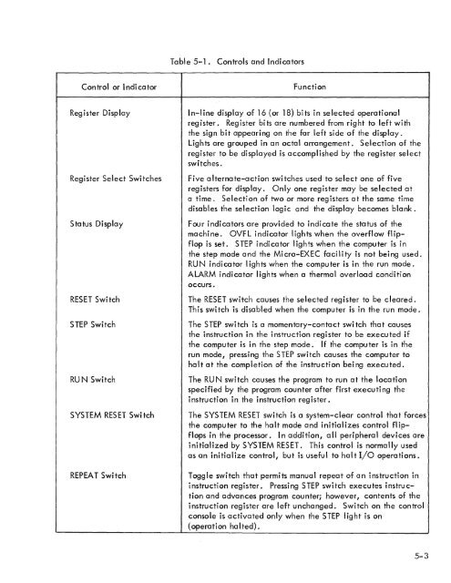
Table 5-1. Controls and Indicators<br />
Control or Indicator<br />
Function<br />
Register Display<br />
Register Select Switches<br />
Status Display<br />
RESET Switch<br />
STEP Switch<br />
RU N Switch<br />
<strong>SYSTEM</strong> RESET Switch<br />
REPEA T SwHch<br />
In-line display of 16 (or 18) bits in selected operational<br />
reg ister. Reg ister bi ts are numbered from rig ht to left wi th<br />
the sign bit appearing on the far left side of the display.<br />
Lights are grouped in an octal arrangement. Selection of the<br />
register to be displayed is accomplished by the register select<br />
switches.<br />
Five alternate-action switches used to select one of five<br />
registers for display. Only one register may be selected at<br />
a time. Selection of two or more registers at the same time<br />
disables the selection logic and the display becomes blank.<br />
Four indicators are provided to indicate the status of the<br />
machine. OVFL indicator lights when the overflow flipflop<br />
is set. STEP indicator lights when the computer is in<br />
the step mode and the Micro-EXEC facility is not being used.<br />
RUN indicator lights when the computer is in the run mode.<br />
ALARM indicator lights when a thermal overload condition<br />
occurs.<br />
The RESET switch causes the selected register to be cleared.<br />
This switch is disabled when the computer is in the run mode.<br />
The STEP switch is a momentary-contact switch that causes<br />
the instruction in the instruction register to be executed if<br />
the computer is in the step mode. If the computer is in the<br />
run mode, pressing the STEP switch causes the computer to<br />
halt at the completion of the instruction being executed.<br />
The RU N switch causes the program to run at the location<br />
specifi ed by the program counter after first execu ti ng the<br />
instruction in the instruction register.<br />
The <strong>SYSTEM</strong> RESET switch is a system-clear control that forces<br />
the computer to the halt mode and initializes control flipflops<br />
in the processor. In addition, all peripheral devices are<br />
initialized by <strong>SYSTEM</strong> RESET. This control is normally used<br />
as an initialize control, but is useful to halt I/O operations.<br />
Toggle switch that permits manual repeat of an instruction in<br />
instruction register. Pressing STEP switch executes instruction<br />
and advances program counter; however, contents of the<br />
instruction register are left unchanged. Switch on the control<br />
console is activated only when the STEP light is on<br />
(operation halted).<br />
5-3


