Fleck 2510 & 2510 Econominder - Pentair Residential Filtration
Fleck 2510 & 2510 Econominder - Pentair Residential Filtration
Fleck 2510 & 2510 Econominder - Pentair Residential Filtration

You also want an ePaper? Increase the reach of your titles
YUMPU automatically turns print PDFs into web optimized ePapers that Google loves.
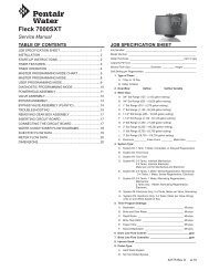
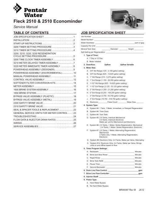
<strong>Fleck</strong> <strong>2510</strong> & <strong>2510</strong> <strong>Econominder</strong><br />
Service Manual<br />
TABLE OF CONTENTS<br />
JOB SPECIFICATION SHEET................................................1<br />
INSTALLATION.......................................................................2<br />
START-UP INSTRUCTIONS...................................................2<br />
3200 TIMER SETTING PROCEDURE...................................3<br />
3210 TIMER SETTING PROCEDURE...................................4<br />
3200, 3210, 3220, 3230 REGENERATION<br />
CYCLE SETTING PROCEDURE............................................5<br />
3200 TIME CLOCK TIMER ASSEMBLY.................................6<br />
3210 METER DELAYED TIMER ASSEMBLY.........................7<br />
3220 METER IMMEDIATE TIMER ASSEMBLY......................8<br />
POWERHEAD ASSEMBLY (DESIGNER)..............................9<br />
POWERHEAD ASSEMBLY (ENVIRONMENTAL)..................10<br />
MANUAL POWERHEAD ASSEMBLY.....................................11<br />
CONTROL VALVE ASSEMBLY...............................................12<br />
SOFTENER FILTER CONVERSION KITS.............................14<br />
METER ASSEMBLY................................................................15<br />
1600 BRINE SYSTEM ASSEMBLY........................................16<br />
1650 BRINE SYSTEM............................................................17<br />
BYPASS VALVE ASSEMBLY (PLASTIC)................................18<br />
BYPASS VALVE ASSEMBLY (METAL)...................................19<br />
2300 SAFETY BRINE VALVE.................................................20<br />
2310 SAFETY BRINE VALVE.................................................21<br />
SEAL & SPACER TOOLS & REPLACEMENT........................22<br />
GENERAL SERVICE HINTS FOR METER CONTROL..........23<br />
TROUBLESHOOTING............................................................24<br />
FLOW DATA & INJECTOR DRAW RATES.............................25<br />
WIRING...................................................................................26<br />
SERVICE ASSEMBLIES.........................................................27<br />
JOB SPECIFICATION SHEET<br />
Job Number:____________________________________________________<br />
Model Number:__________________________________________________<br />
Water Hardness: _______________________________________ ppm or gpg<br />
Capacity Per Unit:________________________________________________<br />
Mineral Tank Size:<br />
_________ Diameter:_ ________ Height:__________<br />
Salt Setting per Regeneration:_ _____________________________________<br />
1. Type of Timer:<br />
A. 7 Day or 12 Day<br />
B. Meter Initiated<br />
2. Downflow: Upflow Upflow Variable<br />
3. Meter Size:<br />
A. 3/4" Std Range (125 - 2,100 gallon setting)<br />
B. 3/4" Ext Range (625 - 10,625 gallon setting)<br />
C. 1" Std Range (310 - 5,270 gallon setting)<br />
D. 1" Ext Range (1,150 - 26,350 gallon setting)<br />
E. 1-1/2" Std Range (625 - 10,625 gallon setting)<br />
F. 1-1/2" Ext Range (3,125 - 53,125 gallon setting)<br />
G. 2" Std Range (1,250 - 21,250 gallon setting)<br />
H. 2" Ext Range (6,250 - 106,250 gallon setting)<br />
I. 3" Std Range (3,750 - 63,750 gallon setting)<br />
J. 3" Ext Range (18,750 - 318,750 gallon setting)<br />
K. Electronic_________ Pulse Count_ ________ Meter Size_ _______<br />
4. System Type:<br />
A. System #4: 1 Tank, 1 Meter, Immediate, or Delayed Regeneration<br />
B. System #4: Time Clock<br />
C. System #4: Twin Tank<br />
D. System #5: 2-5 Tanks, Interlock Mechanical<br />
2-4 Tanks, Interlock Electronic<br />
Meter per unit for Mechanical and Electronic<br />
E. System #6: 2-5 Tanks, 1 Meter, Series Regeneration, Mechanical<br />
2-4 Tanks, 1 Meter, Series Regeneration, Electronic<br />
F. System #7: 2-5 Tanks, 1 Meter, Alternating Regeneration,<br />
Mechanical<br />
2 Tanks only, 1 Meter, Alternating Regeneration,<br />
Electronic<br />
G. System #9: Electronic Only, 2-4 Tanks, Meter per Valve, Alternating<br />
H. System #14: Electronic Only, 2-4 Tanks, Meter per Valve. Brings<br />
units on and offline based on flow.<br />
5. Timer Program Settings:<br />
A. Backwash:____________________________________ Minutes<br />
B. Brine and Slow Rinse:___________________________ Minutes<br />
C. Rapid Rinse:_ _________________________________ Minutes<br />
D. Brine Tank Refill:_______________________________ Minutes<br />
E. Pause Time:__________________________________ Minutes<br />
F. Second Backwash:_ ____________________________ Minutes<br />
6. Drain Line Flow Control:_ ______________________________gpm<br />
7. Brine Line Flow Controller:_____________________________gpm<br />
8. Injector Size#: ____________________________________________<br />
9. Piston Type:<br />
A. Hard Water Bypass<br />
B. No Hard Water Bypass<br />
BR40097 Rev M JA12
INSTALLATION<br />
Water Pressure<br />
A minimum of 20 pounds (1.4 bar) of water pressure is required<br />
for regeneration valve to operate effectively.<br />
Electrical Facilities<br />
An uninterrupted alternating current (A/C) supply is required.<br />
Note: Other voltages are available. Please make sure your<br />
voltage supply is compatible with your unit before installation.<br />
11. Slowly place the by-pass in service position and let water<br />
flow into the mineral tank. When water flow stops, slowly<br />
open a cold water tap nearby and let run until the air is<br />
purged from the unit.<br />
12. Plug unit into an electrical outlet. Note: All electrical<br />
connections must be connected according to local codes.<br />
Be certain the outlet is uninterrupted.<br />
Existing Plumbing<br />
Condition of existing plumbing should be free from lime and<br />
iron buildup. Piping that is built up heavily with lime and/or iron<br />
should be replaced. If piping is clogged with iron, a separate<br />
iron filter unit should be installed ahead of the water softener.<br />
Location Of Softener And Drain<br />
The softener should be located close to a drain to prevent air<br />
breaks and back flow.<br />
BY-PASS VALVES<br />
Always provide for the installation of a by-pass valve if unit is<br />
not equipped with one.<br />
CAUTION Water pressure is not to exceed 125 psi (8.6 bar),<br />
water temperature is not to exceed 110°F (43°C),<br />
and the unit cannot be subjected to freezing<br />
conditions.<br />
Installation Instructions<br />
1. Place the softener tank where you want to install the unit<br />
making sure the unit is level and on a firm base.<br />
2. During cold weather, the installer should warm the valve to<br />
room temperature before operating.<br />
3. All plumbing should be done in accordance with local<br />
plumbing codes. The pipe size for residential drain line<br />
should be a minimum of 1/2" (13 mm). Backwash flow rates<br />
in excess of 7 gpm (26.5 Lpm) or length in excess of 20’<br />
(6 m) require 3/4" (19 mm) drain line. Commercial drain<br />
lines should be the same size as the drain line flow control.<br />
4. Refer to the dimensional drawing for cutting height of the<br />
distributor tube. If there is no dimensional drawing, cut the<br />
distributor tube flush with the top of the tank.<br />
5. Lubricate the distributor O-ring seal and tank O-ring seal.<br />
Place the main control valve on tank. Note: Only use<br />
silicone lubricant.<br />
6. Solder joints near the drain must be done prior to<br />
connecting the Drain Line Flow Control fitting (DLFC).<br />
Leave at least 6" (15 cm) between the DLFC and solder<br />
joints when soldering pipes that are connected on the<br />
DLFC. Failure to do this could cause interior damage to the<br />
DLFC.<br />
7. Teflon tape is the only sealant to be used on the drain<br />
fitting. The drain from twin tank units may be run through a<br />
common line.<br />
8. Make sure that the floor is clean beneath the salt storage<br />
tank and that it is level.<br />
9. Place approximately 1" (25 mm) of water above the grid<br />
plate. If a grid is not utilized, fill to the top of the air check<br />
(Figure 1) in the salt tank. Do not add salt to the brine tank<br />
at this time.<br />
10. On units with a by-pass, place in by-pass position. Turn on<br />
the main water supply. Open a cold soft water tap nearby<br />
and let run a few minutes or until the system is free from<br />
foreign material (usually solder) that may have resulted<br />
from the installation. Once clean, close the water tap.<br />
Figure 1 <strong>Residential</strong> Air Check Valve<br />
START-UP INSTRUCTIONS<br />
60002 Rev E<br />
The water softener should be installed with the inlet, outlet, and<br />
drain connections made in accordance with the manufacturer’s<br />
recommendations, and to meet applicable plumbing codes.<br />
1. Turn the manual regeneraton knob slowly in a clockwise<br />
direction until the program micro switch lifts on top of the<br />
first set of pins. Allow the drive motor to move the piston to<br />
the first regeneration step and stop. Each time the program<br />
switch position changes, the valve will advance to the next<br />
regeneration step. Always allow the motor to stop before<br />
moving to the next set of pins or spaces.<br />
NOTE: For electronic valves, please refer to the manual<br />
regeneration part of the timer operation section.<br />
If the valve came with a separate electronic<br />
timer service manual, refer to the timer<br />
operation section of the electronic timer service<br />
manual.<br />
2. Position the valve to backwash. Ensure the drain line flow<br />
remains steady for 10 minutes or until the water runs clear<br />
(see above).<br />
3. Position the valve to the brine / slow rinse position. Ensure<br />
the unit is drawing water from the brine tank (this step may<br />
need to be repeated).<br />
4. Position the valve to the rapid rinse position. Check the<br />
drain line flow, and run for 5 minutes or until the water runs<br />
clear.<br />
5. Position the valve to the start of the brine tank fill cycle.<br />
Ensure water goes into the brine tank at the desired rate.<br />
The brine valve drive cam will hold the valve in this position<br />
to fill the brine tank for the first regeneration.<br />
6. Replace control box cover.<br />
7. Put salt in the brine tank.<br />
NOTE: Do not use granulated or rock salt.<br />
2 • JA12 <strong>Fleck</strong> <strong>2510</strong> & <strong>2510</strong> <strong>Econominder</strong>
3200 TIMER SETTING PROCEDURE<br />
How To Set Days On Which Water Conditioner Is To<br />
Regenerate (Figure 2)<br />
Rotate the skipper wheel until the number “1” is at the red<br />
pointer. Set the days that regeneration is to occur by sliding<br />
tabs on the skipper wheel outward to expose trip fingers.<br />
Each tab is one day. Finger at red pointer is tonight. Moving<br />
clockwise from the red pointer, extend or retract fingers to<br />
obtain the desired regeneration schedule.<br />
How To Set The Time Of Day<br />
1. Press and hold the red button in to disengage the drive<br />
gear.<br />
2. Turn the large gear until the actual time of day is at<br />
the time of day pointer.<br />
3. Release the red button to again engage the drive gear.<br />
How To Manually Regenerate Your Water Conditioner At<br />
Any Time<br />
1. Turn the manual regeneration knob clockwise.<br />
2. This slight movement of the manual regeneration knob<br />
engages the program wheel and starts the regeneration<br />
program.<br />
3. The black center knob will make one revolution in the<br />
following approximately three hours and stop in the position<br />
shown in the drawing.<br />
4. Even though it takes three hours for this center knob to<br />
complete one revolution, the regeneration cycle of your unit<br />
might be set for only one half of this time.<br />
5. In any event, conditioned water may be drawn after rinse<br />
water stops flowing from the water conditioner drain line.<br />
How to Adjust Regeneration Time<br />
1. Disconnect the power source.<br />
2. Locate the three screws behind the manual regeneration<br />
knob by pushing the red button in and rotating the 24 hour<br />
dial until each screw appears in the cut out portion of the<br />
manual regeneration knob.<br />
3. Loosen each screw slightly to release the pressure on the<br />
time plate from the 24 hour gear.<br />
4. Locate the regeneration time pointer on the inside of the 24<br />
hour dial in the cut out.<br />
5. Turn the time plate so the desired regeneration time aligns<br />
next to the raised arrow.<br />
6. Push the red button in and rotate the 24 hour dial. Tighten<br />
each of the three screws.<br />
7. Push the red button and locate the pointer one more time to<br />
ensure the desired regeneration time is correct.<br />
8. Reset the time of day and restore power to the unit.<br />
61502-3200 Rev A<br />
Figure 2<br />
<strong>Fleck</strong> <strong>2510</strong> & <strong>2510</strong> <strong>Econominder</strong> JA12 • 3
3210 TIMER SETTING PROCEDURE<br />
Typical Programming Procedure<br />
Calculate the gallon capacity of the system, subtract the<br />
necessary reserve requirement and set the gallons available<br />
opposite the small white dot on the program wheel gear (Figure<br />
3).<br />
NOTE: Drawing shows 8,750 gallon setting. The capacity<br />
(gallons) arrow (15) shows zero gallons remaining.<br />
The unit will regenerate tonight at the set<br />
regeneration time.<br />
How To Set The Time Of Day<br />
1. Press and hold the red button in to disengage the drive<br />
gear.<br />
2. Turn the large gear until the actual time of day is opposite<br />
the time of day pointer.<br />
3. Release the red button to again engage the drive gear.<br />
How To Manually Regenerate Your Water Conditioner At<br />
Any Time<br />
1. Turn the manual regeneration knob clockwise.<br />
2. This slight movement of the manual regeneration knob<br />
engages the program wheel and starts the regeneration<br />
program.<br />
3. The black center knob will make one revolution in the<br />
following approximately three hours and stop in the position<br />
shown in the drawing.<br />
4. Even though it takes three hours for this center knob to<br />
complete one revolution, the regeneration cycle of your unit<br />
might be set for only one half of this time.<br />
5. In any event, conditioned water may be drawn after rinse<br />
water stops flowing from the water conditioner drain line.<br />
Immediate Regeneration Timers<br />
These timers do not have a 24 hour gear. Setting the gallons<br />
on the program wheel and manual regeneration procedure are<br />
the same as previous instructions. The timer will regenerate as<br />
soon as the capacity gallons reaches zero.<br />
NOTE: The program wheel to the left may be different than<br />
the program wheel on the product.<br />
NOTE:To set meter capacity rotate manual knob one - 360°<br />
revolution to set gallonage.<br />
Figure 3<br />
61502-3200 Rev A<br />
4 • JA12 <strong>Fleck</strong> <strong>2510</strong> & <strong>2510</strong> <strong>Econominder</strong>
3200, 3210, 3220, 3230 REGENERATION<br />
CYCLE SETTING PROCEDURE<br />
How To Set The Regeneration Cycle Program<br />
The regeneration cycle program on your water conditioner has<br />
been factory preset, however, portions of the cycle or program<br />
may be lengthened or shortened in time to suit local conditions.<br />
3200 Series Timers (Figure 4)<br />
1. To expose cycle program wheel, grasp timer in upper lefthand<br />
corner and pull, releasing snap retainer and swinging<br />
timer to the right.<br />
2. To change the regeneration cycle program, the program<br />
wheel must be removed. Grasp program wheel and<br />
squeeze protruding lugs toward center, lift program wheel<br />
off timer. Switch arms may require movement to facilitate<br />
removal.<br />
3. Return timer to closed position engaging snap retainer in<br />
back plate. Make certain all electrical wires locate above<br />
snap retainer post.<br />
Timer Setting Procedure<br />
How To Change The Length Of Brine Tank Refill Time<br />
1. The second group of holes in the program wheel<br />
determines the length of time that your water conditioner<br />
will refill the brine tank (2 min. per hole).<br />
2. To change the length of refill time, move the two pins at the<br />
end of the second group of holes as required.<br />
3. The regeneration cycle is complete when the outer<br />
microswitch is tripped by the two pin set at end of the brine<br />
tank refill section.<br />
4. The program wheel, however, will continue to rotate until<br />
the inner micro switch drops into the notch on the program<br />
wheel.<br />
How To Change The Length Of The Backwash Time<br />
The program wheel as shown in the drawing is in the service<br />
position. As you look at the numbered side of the program<br />
wheel, the group of pins starting at zero determines the length<br />
of time your unit will backwash.<br />
For example, if there are six pins in this section, the time<br />
of backwash will be 12 min. (2 min. per pin). To change the<br />
length of backwash time, add or remove pins as required. The<br />
number of pins times two equals the backwash time in minutes.<br />
How To Change The Length Of Brine And Rinse Time<br />
1. The group of holes between the last pin in the backwash<br />
section and the second group of pins determines the length<br />
of time that your unit will brine and rinse (2 min. per hole).<br />
2. To change the length of brine and rinse time, move the<br />
rapid rinse group of pins to give more or fewer holes in the<br />
brine and rinse section. Number of holes times two equals<br />
brine and rinse time in minutes.<br />
How To Change The Length Of Rapid Rinse<br />
1. The second group of pins on the program wheel determines<br />
the length of time that your water conditioner will rapid rinse<br />
(2 min. per pin).<br />
2. To change the length of rapid rinse time, add or remove<br />
pins at the higher numbered end of this section as required.<br />
The number of pins times two equals the rapid rinse time in<br />
minutes.<br />
Figure 4<br />
61502-3210 Rev A<br />
<strong>Fleck</strong> <strong>2510</strong> & <strong>2510</strong> <strong>Econominder</strong> JA12 • 5
3200 TIME CLOCK TIMER ASSEMBLY<br />
38<br />
36<br />
37<br />
61502-3200 Rev A<br />
Item No. QTY Part No. Description<br />
1 ................1 ....... 13870 ................Housing, Timer, 3200<br />
2 ................1 ....... 14265 ................Clip, Sping<br />
3 ................3 ....... 14087 ................Insulator<br />
4 ................1 ....... 10896 ................Switch, Micro<br />
5 ................1 ....... 15320 ................Switch, Micro, Timer<br />
6 ................2 ....... 11413 ................Screw, Pan Hd Mach, 4-40 x<br />
1-1/8<br />
7 ................1 ....... 13886 ................Knob, 3200<br />
8 ................5 ....... 13296 ................Screw, Hex Wsh, 6-20 x 1/2<br />
9 ................1 ....... 11999 ................Label, Button<br />
10 ..............1 ....... 13018 ................Pinion, Idler<br />
11 ..............1 ....... 13312 ................Spring, Idler Shaft<br />
12 ..............1 ....... 13017 ................Gear, Idler<br />
13 ..............1 ....... 13164 ................Gear, Drive<br />
14 ..............1 ....... 13887 ................Plate, Motor Mounting<br />
15 ..............1 ....... 18743-1 .............Motor, 120V, 60Hz, 1/30 RPM<br />
1 ....... 18752-1 .............Motor, 100V, 50Hz, 1/30 RPM<br />
1 ....... 18824-1 .............Motor, 230V, 50Hz, 1/30 RPM<br />
1 ....... 18826-1 .............Motor, 24V, 50Hz, 1/30 RPM<br />
1 ....... 19659-1 .............Motor, 24V, 60Hz, 1/30 RPM<br />
1 ....... 19660-1 .............Motor, 230V, 60Hz, 1/30 RPM<br />
16 ..............2 ....... 13278 ................Screw, Sltd Fillister Hd 6-32 x<br />
.156<br />
17 ..............1 ....... 15424 ................Spring, Detent, Timer<br />
18 ..............1 ....... 15066 ................Ball, 1/4”, Delrin<br />
19 ..............1 ....... 15465 ................Label, Caution<br />
6 • JA12 <strong>Fleck</strong> <strong>2510</strong> & <strong>2510</strong> <strong>Econominder</strong><br />
Item No. QTY Part No. Description<br />
20 ..............1 ....... 19210 ................Program Wheel Assy<br />
21 ..............1 ....... 13911 ................Gear, Main Drive, Timer<br />
22 .............17 ...... 41754 ................Pin, Spring, 1/16 x 5/8 SS, Timer<br />
23 ..............1 ....... 13011 ................Arm, Cycle Actuator<br />
24 ..............1 ....... 13864 ................Ring, Skipper Wheel<br />
25 ..............2 ....... 13311 ................Spring, Detent, Timer<br />
26 ..............2 ....... 13300 ................Ball, 1/4”, SS<br />
27 ..............1 ....... 14381 ................Skipper Wheel Assy, 12 Day<br />
1 ....... 14860 ................Skipper Wheel Assy, 7 Day<br />
28 ..............1 ....... 13014 ................Pointer, Regeneration<br />
29 ..............1 ....... 40096-24 ...........Dial, 12 AM Regen Assy, Black<br />
1 ....... 40096-02 ...........Dial, 2 AM Regen Assy, Black<br />
30 ..............1 ....... 13881 ................Bracket, Hinger Timer<br />
31 ..............2 ....... 11384 ................Screw, Phil, 6-32 x 1/4 Zinc<br />
32 ..............1 ....... 13902 ................Harness, 3200<br />
33 ..............2 ....... 40422 ................Nut, Wire, Tan<br />
34 ..............1 ....... 15354-01 ...........Wire, Ground, 4”<br />
35 ..............1 ....... 14007 ................Label, Time of Day<br />
36 ..............1 ....... * ........................Complete 3200 Time Clock<br />
Timer Assembly<br />
37 ........................ 60320-02 ...........Switch Kit, 3200/9000 Timer<br />
Auxiliary, Optional<br />
38 ........................ 61420-03 ...........Program Wheel, Gear Assy,<br />
Filter 2 Min Per Pin<br />
............................ 61420-04 ...........Program Wheel, Gear Assy,<br />
Softener, 2 Min Per Pin<br />
*Call your distributor for Part Number
3210 METER DELAYED TIMER<br />
ASSEMBLY<br />
41<br />
43<br />
40<br />
42<br />
61502-3210 Rev A<br />
Item No. QTY Part No. Description<br />
1 ................1 ....... 13870 ................Housing, Timer, 3200<br />
2 ................1 ....... 13802 ................Gear, Cycle Actuator<br />
3 ................1 ....... 40096-02 ...........Dial 2 AM Regen Assy, Black<br />
4 ................1 ....... 13886 ................Knob, 3200<br />
5 ................4 ....... 13296 ................Screw, Hex Wsh, 6-20 x 1/2<br />
6 ................2 ....... 11999 ................Label, Button<br />
7 ................1 ....... 13803 ................Gear, Program Drive Wheel<br />
8 ................1 ....... 13806 ................Retainer, Program Wheel<br />
9 ................1 ....... 13748 ................Screw, Flat Head St, 6-20 x 1/2<br />
10 ..............1 ....... 14265 ................Clip, Spring<br />
11 ..............1 ....... 15424 ................Spring, Detent, Timer<br />
12 ..............1 ....... 15066 ................Ball, 1/4” Delrin<br />
13 ..............1 ....... 13018 ................Pinion, Idler<br />
14 ..............1 ....... 13312 ................Spring, Idler Shaft<br />
15 ..............1 ....... 13017 ................Gear, Idler<br />
16 ..............1 ....... 13164 ................Gear, Drive<br />
17 ..............1 ....... 13887 ................Plate, Motor Mounting<br />
18 ..............1 ....... 18743-1 .............Motor, 120V, 60Hz 1/30 RPM<br />
1 ....... 18752-1 .............Motor, 100V, 50Hz, 1/30 RPM<br />
1 ....... 18824-1 .............Motor, 230V, 50Hz, 1/30 RPM<br />
1 ....... 18826-1 .............Motor, 24V, 50Hz, 1/30 RPM<br />
1 ....... 19659-1 .............Motor, 24V, 60Hz, 1/30 RPM<br />
1 ....... 19660-1 .............Motor, 230V, 60Hz, 1/30 RPM<br />
19 ..............1 ....... 13278 ................Screw, Fillister Hd, 6-32 x .156<br />
20 ..............1 ....... 13830 ................Pinion, Program Wheel Drive<br />
21 ..............1 ....... 13831 ................Clutch, Drive Pinion<br />
22 ..............1 ....... 14276 ................Spring, Meter, Clutch<br />
23 ..............1 ....... 14253 ................Retainer, Clutch Spring<br />
24 ..............3 ....... 11384 ................Screw, Phil, 6-32 x 1/4<br />
25 ..............1 ....... 13881 ................Bracket, Hinge Timer<br />
Item No. QTY Part No. Description<br />
26 ..............3 ....... 14087 ................Insulator<br />
27 ..............1 ....... 10896 ................Switch, Micro<br />
28 ..............1 ....... 15320 ................Switch, Micro, Timer<br />
29 ..............2 ....... 11413 ................Screw, Pan Hd Mach, 4-40 x 1 1/8<br />
30 ..............1 ....... 14198 ................Label, Indicator<br />
31 ..............1 ....... 15465 ................Label, Caution<br />
32 ..............1 ....... 14007 ................Label, Time of Day<br />
33 ..............1 ....... 14045 ................Label, Instruction<br />
34 ..............1 ....... 13902 ................Harness, 3200<br />
35 ..............2 ....... 40422 ................Nut, Wire, Tan<br />
36 ..............1 ....... 15354-01 ...........Wire, Ground, 4”<br />
37 ..............1 ....... 19210 ................Program Wheel Assy<br />
38 .............17 ...... 41754 ................Pin, Spring, 1/16 x 5/8 SS, Timer<br />
39 ..............1 ....... 13911 ................Gear, Main Drive, Timer<br />
40 ..............1 ....... * ........................Complete 3210 Meter Delayed<br />
Timer Assembly<br />
41 ........................ 60405-10 ...........Program Wheel, w/3/4" STD Label<br />
0-2,100 gal<br />
........ 60405-20 ...........Program Wheel, w/3/4" EXT Label<br />
0-10,000 gal<br />
..........60405-11 .............Program Wheel, w/3/4" STD Metric<br />
Label 0-8 m3<br />
..........60405-21.............Program Wheel, w/3/4" EXT<br />
Range 0-40 m3<br />
42 ........................ 60320-02 ...........Switch Kit, 3200/9000 Timer<br />
Auxiliary, Optional<br />
43 ........................ 61420-03 ...........Program Wheel, Gear Assy,<br />
Filter 2 Min Per Pin<br />
........ 61420-04 ...........Program Wheel, Gear Assy,<br />
Softener, 2 Min Per Pin<br />
*Call your distributor for Part Number<br />
<strong>Fleck</strong> <strong>2510</strong> & <strong>2510</strong> <strong>Econominder</strong> JA12 • 7
3220 METER IMMEDIATE TIMER<br />
ASSEMBLY<br />
31<br />
33<br />
32<br />
1<br />
30<br />
27<br />
2<br />
3<br />
4<br />
5<br />
29<br />
9<br />
1<br />
28<br />
6<br />
10<br />
11<br />
36<br />
35<br />
34<br />
40<br />
39<br />
7<br />
8<br />
5<br />
38<br />
37<br />
17<br />
21<br />
22<br />
23<br />
24<br />
23<br />
25<br />
18 19<br />
20<br />
Item No. QTY Part No. Description<br />
1 ................1 ....... 13870 ................Housing, Timer<br />
2 ................1 ....... 15431 ................Gear, Cycle Actuator, System #5<br />
3 ................1 ....... 13886 ................Knob, 3200<br />
4 ................4 ....... 13296 ................Screw, Hex Wsh, 6-20 x 1/2<br />
5 ................2 ....... 11999 ................Label, Button<br />
6 ................1 ....... 13807 ................Gear, Program Drive Wheel<br />
7 ................1 ....... 13806 ................Retainer, Program Wheel<br />
8 ................1 ....... 13748 ................Screw, Flt Hd St, 6-20 x 1/2<br />
9 ................1 ....... 14265 ................Spring Clip<br />
10 ..............1 ....... 13018 ................Pinion, Idler<br />
11 ..............1 ....... 18563 ................Idler Shaft Spring<br />
12 ..............1 ....... 13017 ................Gear, Idler<br />
13 ..............1 ....... 13164 ................Drive Gear<br />
14 ..............1 ....... 13887 ................Plate, Motor Mounting<br />
15 ..............1 ....... 18743-1 .............Motor, 120V, 60 Hz, 1/30 RPM<br />
1 ....... 18752-1 .............Motor, 100V, 50Hz, 1/30 RPM<br />
1 ....... 18824-1 .............Motor, 230V, 50Hz, 1/30 RPM<br />
1 ....... 18826-1 .............Motor, 24V, 50Hz, 1/30 RPM<br />
1 ....... 19659-1 .............Motor, 24V, 60Hz, 1/30 RPM<br />
1 ....... 19660-1 .............Motor, 230V, 60Hz, 1/30 RPM<br />
16 ..............2 ....... 13278 ................Screw, Sltd Fillister Hd<br />
17 ..............1 ....... 14502 ................Pinion, Program Wheel<br />
18 ..............1 ....... 14501 ................Clutch, Drive Pinion<br />
19 ..............1 ....... 14276 ................Meter Clutch Spring<br />
20 ..............1 ....... 14253 ................Retainer, Clutch Spring<br />
21 ..............3 ....... 11384 ................Screw, Phil, 6-32 x 1/4 Zinc<br />
22 ..............1 ....... 13881 ................Bracket, Hinge Timer<br />
23 ..............3 ....... 14087 ................Insulator<br />
24 ..............1 ....... 15414-00 ...........Micro Switch<br />
8 • JA12 <strong>Fleck</strong> <strong>2510</strong> & <strong>2510</strong> <strong>Econominder</strong><br />
23<br />
26<br />
12<br />
13<br />
14<br />
21<br />
15<br />
16<br />
4<br />
Item No. QTY Part No. Description<br />
61502-3220 Rev B<br />
25 ..............1 ....... 15320 ................Switch, Micro, Timer<br />
26 ..............2 ....... 11413 ................Screw, Pan Hd Mach, 4-40 x 1-1/8<br />
27 ..............1 ....... 14198 ................Label, Indicator<br />
28 ..............1 ....... 15465 ................Label, Caution<br />
29 ..............1 ....... 14007 ................Label, Time of Day<br />
30 ..............1 ....... 15148 ................Label, Instruction<br />
31 ..............1 ....... 40617 ................Harness, 3220<br />
32 ..............2 ....... 40422 ................Nut, Wire, Tan<br />
33 ..............1 ....... 15354-01 ...........Wire, Ground, 4"<br />
34 ..............1 ....... 19210-05 ...........Program Wheel Assembly,<br />
9000/3230<br />
35 .............17 ...... 41754 ................Pin, Spring, 1/16 x 5/8 Stainless<br />
Steel, Timer<br />
36 ..............1 ....... 15055 ................Gear, Main Drive<br />
37 ..............1 ....... * ........................Complete 3220 Meter Immediate<br />
Timer Assembly<br />
38 ........................ 60405-10 ...........Program Wheel, w/3/4" STD Label<br />
0-2,100 gal<br />
........ 60405-20 ...........Program Wheel, w/3/4" EXT Label<br />
0-10,000 gal<br />
..........60405-11 .............Program Wheel, w/3/4" STD Metric<br />
Label 0-8 m3<br />
..........60405-21.............Program Wheel, w/3/4" EXT<br />
Range 0-40 m3<br />
39 ........................ 60320-02 ...........Switch Kit, 3200/9000 Timer<br />
Auxiliary, Optional<br />
40 ........................ 61420-06 ...........Program Wheel, Gear Assy,<br />
Softener Immediate 2 Min Per<br />
Pin<br />
........ 61420-42 ...........Program Wheel, Gear Assy,<br />
Filter Immediate 2 Min Per Pin<br />
*Call your distributor for Part Number
POWERHEAD ASSEMBLY (DESIGNER)<br />
23<br />
18A<br />
21<br />
22<br />
61502_<strong>2510</strong> Rev B<br />
Item No. QTY Part No. Description<br />
1 ................1 ....... 40264 ................Backplate, SS/Service Valve<br />
Operator, W-T-Screws<br />
2 ................1 ..................................3200, Timer 7 or 12 Day<br />
3 ................1 ....... 11838 ................Power Cord, North America<br />
........ 19303-01 ...........Austrailian Cord<br />
........ 19885-01 ...........Japanese Cord<br />
........ 11545-01 ...........European Cord<br />
4 ................1 ....... 13547 ................Strain Relief<br />
5 ................1 ....... 40400 ................Harness, Drive, Designer/<br />
Environmental<br />
8 ................2 ....... 10231 ................Screw - Drive Mounting<br />
9 ................2 ....... 10302 ................Insulator<br />
10 ..............2 ....... 10218 ................Switch<br />
11 ..............1 ....... 10909 ................Connecting Link Pin<br />
12 ..............1 ....... 10250 ................Retaining Ring<br />
13 ..............1 ....... 10621 ................Connecting Link<br />
14 ..............1 ....... 12576 ................Drive Cam - STF (Black)<br />
15 ..............2 ....... 10338 ................Roll Pin<br />
16 ..............1 ....... 13366 ................Drive Bearing<br />
17 ..............2 ....... 14923 ................Screw - Switch Mounting<br />
18 ..............1 ....... 41543* ..............Motor, Drive, 115V, 50/60Hz<br />
........ 41545* ..............Motor, Drive, 230V, 50/60Hz<br />
Item No. QTY Part No. Description<br />
18A ...........1 ....... 42579** .............Motor, Drive, 24VAC/VDC,<br />
50/60Hz<br />
20 ..............1 ....... 12777 ................Brine Valve Cam - Separate<br />
Time Fill (Black)<br />
21 ........................ *** ......................Switch Kit, 1500 thru 2850,<br />
Optional<br />
22 ..............1 ....... 60160-15 ...........Drive Cam Assy STF, Blue<br />
23 ........................ *** ......................Powerhead Assy<br />
Not Shown:<br />
2 ....... 10300 ................Screw - Timer Mounting<br />
1 ....... 13741 ................Hole Plug<br />
1 ....... 17904 ................Hole Plug<br />
2 ....... 19367 ................Screw, Thumb<br />
1 ....... 15441 ................Cable Guide Assy<br />
1 ....... 15495 ................Meter Cable, 13.87”<br />
1 ....... 60232-110 .........Cover, Designer, 1 Pc. Black<br />
* Bracket is integrated into the motor.<br />
** Bracket is integrated into the motor and picture may not reflect<br />
actual component.<br />
***Call your distributor for Part Number<br />
Motor drawing may not resemble actual.<br />
For Service Assembly Numbers, See the Back of this Manual<br />
<strong>Fleck</strong> <strong>2510</strong> & <strong>2510</strong> <strong>Econominder</strong> JA12 • 9
POWERHEAD ASSEMBLY<br />
(ENVIRONMENTAL)<br />
20<br />
13<br />
19<br />
17<br />
23<br />
20<br />
19<br />
15<br />
20<br />
19 16<br />
18<br />
21<br />
3<br />
26<br />
28<br />
18<br />
14<br />
2<br />
27<br />
25<br />
4<br />
1<br />
29<br />
24<br />
7<br />
6<br />
10<br />
11A<br />
12<br />
9<br />
8<br />
5<br />
9<br />
11<br />
22<br />
BR61501-1500 Rev C<br />
Item No. QTY Part No. Description<br />
1 ................1 ....... 18697-15 ...........Backplate, Hinged<br />
2 ................1 ....... 11838 ................Power Cord, 6’, North American,<br />
Flat<br />
........ 19303-01 ...........Power Cord, 6’, Austrailian<br />
........ 19885-01 ...........Power Cord, 6’, Japanese<br />
........ 11545-01 ...........Power Cord, 6’, European<br />
3 ................1 ....... 13547 ................Strain Relief, Cord<br />
4 ................1 ....... 40400 ................Harness, Drive Designr/Envirmtl<br />
5 ................2 ....... 10231 ................Screw, Slot Hex 1/4-20 x 1/2<br />
35 IN-LBS ±20%<br />
6 ................2 ....... 10218 ................Switch, Micro<br />
7 ................1 ....... 10909 ................Pin, Connecting Rod Spring<br />
8 ................1 ....... 60160-15 ...........Drive Cam Assy, STF, Blue, 2900<br />
9 ................2 ....... 10338 ................Pin, Roll, 3/32 x 7/8<br />
10 ..............2 ....... 14923 ................Screw, Pan Hd MACH, 4-40 x 1<br />
5.0 IN-LBS ±10%<br />
11 ..............1 ....... 41543 ................Motor, Drive, 115V/60 Hz<br />
........ 41545 ................Motor, Drive, 220V, 50-60Hz, SP,<br />
Fam 1<br />
11A ...................... 42579 ................Motor, Drive, 24 VAC/DC, 50-60<br />
Hz, Fam 1<br />
12 ..............1 ....... 12777 ................Cam, Shut-off Valve<br />
13 ..............2 ....... 10300 ................Screw, Hx Wash Head, 8 x 3/8<br />
20 IN-LBS ±20%<br />
14 ..............1 ....... 3200 ..................Timer Assy, 3200 7 or 12 Day<br />
...................................3210 Meter Delay<br />
...................................3220 Meter Immediate<br />
15 ..............1 ....... 15806 ................Hole Plug, (HeyCo)<br />
10 • JA12 <strong>Fleck</strong> <strong>2510</strong> & <strong>2510</strong> <strong>Econominder</strong><br />
Item No. QTY Part No. Description<br />
16 ..............1 ....... 16493 ................Plug, Hole, HeyCo, .88 Dia<br />
17 ..............1 ....... 17421 ................Plug, 1.20 Hole<br />
18 ..............2 ....... 19691 ................Plug, .750 Dia. Hole, Flush<br />
19 ..............7 ....... 19800 ................Plug (Hole Size: Dia .140)<br />
20 ..............4 ....... 19801 ................Plug, Dia .190<br />
21 ..............1 ....... 10712 ................Fitting, Brine Valve<br />
(Used on Filter Valves)<br />
22 ..............1 ....... 10269 ................Nut, Jam, 3/4-16 (Used on FIlter<br />
Valves) Wrench Tighten<br />
23 ..............2 ....... 41581 ................Plug, Hole .125 Dia, White<br />
24 ..............1 ....... 10872 ................Screw, Hex WSH, 8-32 x 5/16<br />
20 IN-LBS ±20%<br />
25 ..............1 ....... 14202-01 ...........Screw, Hex Washer #8-32 x 5/16<br />
Hand Tighten<br />
26 ..............1 ....... 60219-02 ...........Cover Assy, Environmental,<br />
Black, Clear Window<br />
........ 60219-12 ...........Cover Assy, Environmental,<br />
Black, Black Window<br />
27 ..............1 ....... * ........................Powerhead Assembly<br />
28 ..............1 ....... 60050-23 ...........Drive Motor Assy, 24 VAC/DC,<br />
50-60 Hz FAM 1<br />
........ 60050-21 ...........Drive Motor Assy, 115V/60 Hz<br />
........ 60050-22 ...........Drive Motor Assy, 220V, 50-60<br />
Hz SP FAM1<br />
29 ........................ 60320-12 ...........Switch Kit, 1500-2850 Drive<br />
Motor<br />
Not Shown:<br />
1 ....... 15441 ................Cable Guide Assy, <strong>2510</strong><br />
1 ....... 15495 ................Meter Cable, 13.87"<br />
*Call your distributor for Part Number
MANUAL POWERHEAD ASSEMBLY<br />
1<br />
9<br />
10<br />
2<br />
5<br />
4<br />
3<br />
6<br />
8<br />
7<br />
Item No. QTY Part No. Description<br />
1 ................1 ....... 12593 ................Backplate, Manual<br />
2 ................1 ....... 12592 ................Bracket, Lever Position<br />
3 ................1 ....... 12596 ................Screw, Spec Mach, 1/4 - 20 x 1/2<br />
4 ................1 ....... 12707 ................Washer, Spring<br />
5 ................1 ....... 11235 ................Nut, Hex, 1/4 - 20, Mach Screw,<br />
Zinc<br />
6 ................1 ....... 12594 ................Lever, Valve Position<br />
7 ................2 ....... 10231 ................Screw, Slot Hex, 1/4 - 20 x 1/2<br />
18-8 SS<br />
8 ................1 ....... 60224-32 ...........Cover Assy, Manual, Filter<br />
1 ....... 60224-33 ...........Cover Assy, Manual, Softener<br />
9 ................4 ....... 10300 ................Screw, Slot Hex Wsh, 8-18 x 3/8<br />
Type “B” RC44-47<br />
10 ........................ 60409 ................Powerhead Assy, Manual<br />
Not Shown:<br />
1 ....... 10909 ................Pin, Link<br />
60409 Rev A<br />
<strong>Fleck</strong> <strong>2510</strong> & <strong>2510</strong> <strong>Econominder</strong> JA12 • 11
CONTROL VALVE ASSEMBLY<br />
23<br />
36<br />
31<br />
22<br />
21<br />
29<br />
20<br />
30<br />
38<br />
27<br />
26<br />
37<br />
37<br />
18<br />
17<br />
5<br />
32<br />
25<br />
35<br />
37<br />
19<br />
24<br />
4<br />
3<br />
2<br />
37<br />
10<br />
1<br />
34<br />
11<br />
33<br />
8<br />
7<br />
9<br />
12<br />
6<br />
13<br />
16<br />
14<br />
15<br />
61500-<strong>2510</strong> Rev B<br />
12 • JA12 <strong>Fleck</strong> <strong>2510</strong> & <strong>2510</strong> <strong>Econominder</strong>
CONTROL VALVE ASSEMBLY continued<br />
Item No. QTY Part No. Description<br />
1 ................1 ....... 19328 ................Valve Body, <strong>2510</strong><br />
2 ................1 ....... 11385-01 ...........Housing, Flow Control, Plastic<br />
3 ................1 ....... 11183 ................O-ring, -017<br />
4 ................1 ....... 12408 ................Washer, Flow, 7.0 GPM<br />
5 ................1 ....... 18312 ................Retainer, Drain<br />
6 ................1 ....... 19322 ................Adapter Base, <strong>2510</strong><br />
7 ................1 ....... 19936 ................Seal, <strong>2510</strong>, Base<br />
8 ................1 ....... 19899 ................Clamp, Female, <strong>2510</strong><br />
9 ................1 ....... 19900 ................Clamp, Male, <strong>2510</strong><br />
10 ..............1 ....... 40000 ................Pin, Hinge, Clamp<br />
11 ..............1 ....... 19998 ................Pivot, Clamp, <strong>2510</strong><br />
12 ..............1 ....... 40057 ................Screw, Comb Hd, 114-20, 2"<br />
13 ..............1 ....... 19197 ................Ring, Slip<br />
14 ..............1 ....... 18303 ................O-ring, -336<br />
15 ..............1 ....... 13030 ................Retainer, Dist Tube, O-ring<br />
16 ..............1 ....... 13304 ................O-ring, -121<br />
17 ..............1 ....... 17776 ................Body, Injector, 1600<br />
18 ..............1 ....... 10328 ................Fitting, Elbow, 90 Deg. 1/4" NPT<br />
x 3/8" Tube<br />
19 ..............1 ....... 16221 ................Disperser, Air<br />
20 ..............1 ....... 10227 ................Screen, Injector<br />
21 ..............1 ....... 10229 ................Gasket, Injector Cap, 1600<br />
22 ..............1 ....... 11893 ................Cap, Injector, SS<br />
23 ..............2 ....... 10692 ................Screw, Slot Hex Hd, 10-24 x<br />
1-5/8"<br />
24 ..............1 ....... 14805 ................Gasket, Injector Body, 1600/1700<br />
25 ..............1 ....... 12338 ................Fitting, Elbow, 90 Deg. 1/2" NPT<br />
x 1/2" Barb<br />
26 ..............1 ....... 11893 ................Cap, Injector, Stainless Steel<br />
........ 10228 ................Cap, Injector, Brass<br />
27 ..............1 ....... 15137 ................Screw, Hex Wsh Mach, 10-24 x<br />
3/8<br />
28 ..............1 ....... 10757 ................Spacer, End<br />
29 ..............1 ....... 12973-0 .............Nozzle, Injector, #0, PVC<br />
........ 12973-1 .............Nozzle, Injector, #1, PVC<br />
........ 12973-2 .............Nozzle, Injector, #2, PVC<br />
........ 12973-3 .............Nozzle, Injector, #3, PVC<br />
........ 12973-4 .............Nozzle, Injector, #4, PVC<br />
........ 10913-000 .........Nozzle, Injector, #000 Brown<br />
........ 10913-00 ...........Nozzle, Injector, #00 Violet<br />
........ 10913-0 .............Nozzle, Injector, #0 Red<br />
........ 10913-1 .............Nozzle, Injector, #1 White<br />
........ 10913-2 .............Nozzle, Injector, #2 Blue<br />
........ 10913-3 .............Nozzle, Injector, #3 Yellow<br />
........ 10913-4 .............Nozzle, Injector, #4 Green<br />
30 ..............1 ....... 12974-0 .............Throat, Injector, #0, PVC<br />
........ 12974-1 .............Throat, Injector, #1, PVC<br />
........ 12974-2 .............Throat, Injector, #2, PVC<br />
........ 12974-3 .............Throat, Injector, #3, PVC<br />
........ 12974-4 .............Throat, Injector, #4, PVC<br />
........ 10914-000 .........Throat, Injector, #000 Brown<br />
........ 10914-00 ...........Throat, Injector, #00 Violet<br />
........ 10914-0 .............Throat, Injector, #0 Red<br />
........ 10914-1 .............Throat, Injector, #1 White<br />
........ 10914-2 .............Throat, Injector, #2 Blue<br />
........ 10914-3 .............Throat, Injector, #3 Yellow<br />
........ 10914-4 .............Throat, Injector, #4 Green<br />
Item No. QTY Part No. Description<br />
31 ..............1 ....... 60480-000 .........Injector Assy, 1600 #00, Plastic<br />
........ 60480-00 ...........Injector Assy, 1600 #0, Plastic<br />
........ 60480-01 ...........Injector Assy, 1600 #1, Plastic<br />
........ 60480-02 ...........Injector Assy, 1600 #2, Plastic<br />
........ 60480-03 ...........Injector Assy, 1600 #3, Plastic<br />
........ 60480-04 ...........Injector Assy, 1600 #4, Plastic<br />
32 ..............1 ....... 60705-00 ...........DLFC, Plastic Blank<br />
........ 60705-06 ...........DLFC, Plastic 0.60 gpm<br />
........ 60705-08 ...........DLFC, Plastic 0.80 gpm<br />
........ 60705-10 ...........DLFC, Plastic 1.0 gpm<br />
........ 60705-12 ...........DLFC, Plastic 1.2 gpm<br />
........ 60705-13 ...........DLFC, Plastic 1.3 gpm<br />
........ 60705-15 ...........DLFC, Plastic 1.5 gpm<br />
........ 60705-17 ...........DLFC, Plastic 1.7 gpm<br />
........ 60705-20 ...........DLFC, Plastic 2.0 gpm<br />
........ 60705-24 ...........DLFC, Plastic 2.4 gpm<br />
........ 60705-30 ...........DLFC, Plastic 3.0 gpm<br />
........ 60705-35 ...........DLFC, Plastic 3.5 gpm<br />
........ 60705-40 ...........DLFC, Plastic 4.0 gpm<br />
........ 60705-45 ...........DLFC, Plastic 4.5 gpm<br />
........ 60705-50 ...........DLFC, Plastic 5.0 gpm<br />
........ 60705-60 ...........DLFC, Plastic 6.0 gpm<br />
........ 60705-70 ...........DLFC, Plastic 7.0 gpm<br />
........ 60706-8.0 ..........DLFC, QC x 3/4"F, 8.0 gpm<br />
........ 60706-9.0 ..........DLFC, QC x 3/4"F, 9.0 gpm<br />
........ 60706-10 ...........DLFC, QC x 3/4"F, 10 gpm<br />
........ 60706-12 ...........DLFC, QC x 3/4"F, 12 gpm<br />
........ 60706-15 ...........DLFC, QC x 3/4"F, 15 gpm<br />
........ 60706-20 ...........DLFC, QC x 3/4"F, 20 gpm<br />
33 ..............1 ....... 60090 ................Piston Assy, 1500, <strong>2510</strong>, 2750<br />
34 ..............1 ....... 60121 ................Seal Kit, 1500, <strong>2510</strong>, 2750<br />
1 ....... 60121-10 ...........Seal and Spacer Kit, <strong>2510</strong>, 2750,<br />
Silicone<br />
35 ..............1 ....... 60101-01 ...........Piston Assy, NHWBP<br />
36 ..............2 ....... 19228-01 ........... Adapter Assy, Coupling w/O-ring<br />
37 ..............4 ....... 13305 ................O-ring, -119<br />
38 ..............1 ....... 14805 ................Gasket, Injector Body, 1600/1700<br />
Not Shown<br />
1 ....... 11098 ................Stuffer Tool Assy, <strong>2510</strong>/2750<br />
1 ....... 13061 ................Puller Assy, Port Ring <strong>2510</strong>/2750<br />
1 ....... 12874 ................Hook, Seal<br />
NOTE: For optimal seal life, the use of lubricants is not<br />
recommended.<br />
<strong>Fleck</strong> <strong>2510</strong> & <strong>2510</strong> <strong>Econominder</strong> JA12 • 13
SOFTENER FILTER CONVERSION KITS<br />
1 2<br />
61671 Rev E<br />
Item No. QTY Part No. Description<br />
1 .......................... 60101-02 ...........Piston Conversion, No Seals, No<br />
Spacers, <strong>2510</strong> NHWBP 1600<br />
2 .......................... 60101-00 ...........Piston Kit, No Seals, No<br />
Spacers, <strong>2510</strong> NHWBP Filter<br />
NOTE: For optimal seal life, the use of lubricants is not<br />
recommended.<br />
14 • JA12 <strong>Fleck</strong> <strong>2510</strong> & <strong>2510</strong> <strong>Econominder</strong>
METER ASSEMBLY<br />
10<br />
60088 Rev E<br />
Item No. QTY Part No. Description<br />
1 ................4 ....... 12473 ................Screw - Meter Cover Assembly,<br />
10-24 x 5/8"<br />
2 ................1 ....... 15659 ................Meter Cover Assy. - Ext., Rt.<br />
Angle (Not Shown)<br />
1 ....... 15452 ................Meter Cap Assy, 3/4" to 2", Std,<br />
Rt Ang/90, Plastic Paddle<br />
3 ................1 ....... 13847 ................O-ring - Meter Cover Assembly,<br />
-137<br />
4 ................1 ....... 13509 ................Impeller<br />
5 ................4 ....... 13314 ................Screw - Adapter Clip, 8-18 x 0.6"<br />
6 ................4 ....... 13255 ................Adapter Clip<br />
7 ................1 ....... 13821 ................Meter Body<br />
8 ................4 ....... 13305 ................O-ring - Meter Body, -119<br />
9 ................1 ....... 14613 ................Flow Straightener<br />
10 ..............1 ....... 60088-180 .........Meter Assy, 3/4" Dual Port, Slip<br />
Std, RT Angle/180 Plastic Paddle<br />
Wheel, w/clips<br />
1 ....... 60089-180 .........Meter Assy, 3/4" Dual Port,<br />
Slip, EXT, RT Angle/180 Plastic<br />
Paddle Wheel, w/clips<br />
<strong>Fleck</strong> <strong>2510</strong> & <strong>2510</strong> <strong>Econominder</strong> JA12 • 15
1600 BRINE SYSTEM ASSEMBLY<br />
16<br />
60029 Rev C<br />
Item No. QTY Part No. Description<br />
1 ................2 ....... 10332 ................Fitting, Insert, 3/8<br />
2 ................1 ....... 12767 ................Screen, Brine<br />
3 ................1 ....... 10328 ................Fitting, Elbow, 90 Deg. 1/4" NPT<br />
x 3/8Tube<br />
4 ................3 ....... 10329 ................Fitting, Tube, 3/8 Nut, Brass<br />
5 ................3 ....... 10330 ................Fitting, Sleeve, 3/8 Celcon<br />
6 ................1 ....... 16508-01 ...........Tube, Brine Valve, 2850/2900s<br />
1 ....... 12774 ................Tube, Brine Valve, 1500<br />
1 ....... 40027 ................Tube, Brine Valve, <strong>2510</strong>, HWBP<br />
1 ....... 14228 ................Tube, Brine Valve, <strong>2510</strong>,<br />
NHWBP<br />
1 ....... 15221-01 ...........Tube, Brine Valve, 2750/2900<br />
1 ....... 42184 ................Tube, Brine Valve, 2850s<br />
1 ....... 41683 ................Tube, Brine Valve, UF, 2900S<br />
1600/1650<br />
7 ................1 ....... 10250 ................Ring, Retaining<br />
8 ................1 ....... 11749 ................Guide, Brine Valve Stem<br />
Item No. QTY Part No. Description<br />
9 ................1 ....... 10249 ................Spring, Brine Valve<br />
10 ..............1 ....... 12550 ................Quad Ring, -009<br />
11 ..............1 ....... 12748 ................Brine Valve Body Assy, 1600 w/<br />
Quad Ring<br />
12 ..............1 ....... 12552-02 ...........Brine Valve Stem, 1600, with<br />
Seat<br />
13 ..............1 ....... 12626 ................Seat, Brine Valve<br />
14 ..............1 ....... 11982 ................O-ring, -016<br />
15 ..............1 ....... 60020-25 ...........BLFC, .25 GPM, 1600<br />
1 ....... 60020-50 ...........BLFC, .50 GPM, 1600<br />
1 ....... 60020-100 .........BLFC, 1.0 GPM, 1600<br />
16 ..............1 ....... 60029-010 .........Brine Valve, 1600 Short Stem,<br />
0.25 gpm<br />
........ 60029-020 .........Brine Valve, 1600 Short Stem,<br />
0.50 gpm<br />
........ 60029-030 .........Brine Valve, 1600 Short Stem,<br />
1.00 gpm<br />
16 • JA12 <strong>Fleck</strong> <strong>2510</strong> & <strong>2510</strong> <strong>Econominder</strong>
1650 BRINE SYSTEM<br />
20<br />
60011 Rev D<br />
Item No. QTY Part No. Description<br />
1 ................1 ....... 10328 ................Elbow, 90 1/4 NPT x 3/8<br />
3 ................3 ....... 10332 ................Insert, 3/8<br />
4 ................1 ....... 10330 ................Sleeve, 3/8 Nut Brine<br />
5 ................1 ....... 10329 ................Tube Fitting, 3/8 Nut Brine<br />
6 ................1 ....... 16508-01 ...........Tube, Brine Valve, 2850/2900s<br />
1 ....... 12774 ................Tube, Brine Valve, 1500<br />
1 ....... 40027 ................Tube, Brine Valve, <strong>2510</strong>, HWBP<br />
1 ....... 14228 ................Tube, Brine Valve, <strong>2510</strong>,<br />
NHWBP<br />
1 ....... 15221-01 ...........Tube, Brine Valve, 2750/2900<br />
1 ....... 42184 ................Tube, Brine Valve, 2850s<br />
1 ....... 41683 ................Tube, Brine Valve, UF, 2900S<br />
1600/1650<br />
7 ................2 ....... 19625 ................Assy., GFN Nut<br />
8 ................1 ....... 16924 ................O-ring, -018<br />
9 ................1 ....... 12626 ................Seat, Brine Valve<br />
10 ..............1 ....... 12552 ................Brine Valve Stem, 1600<br />
12 ..............1 ....... 17906 ................Guide, Brine Valve Stem<br />
13 ..............1 ....... 10250 ................Retaining Ring<br />
14 ..............1 ....... 10249 ................Spring, Brine Valve<br />
15 ..............1 ....... 17884 ................Brine Valve Body Assy., Plastic<br />
17 ..............1 ....... 12794 ................Elbow, 3/8 Tube Poly, White<br />
18 ..............1 ....... 60002 ................#500 Air Check<br />
Item No. QTY Part No. Description<br />
19 ........................ 60010-25 BLFC Assy. (Parts)<br />
1 ....... 17907 ................Housing<br />
1 ....... 12128 .................25 GPM Label<br />
1 ....... 12094 .................25 Flow Washer<br />
1 ....... 12098 ................Retainer<br />
60010-50 BLFC Assy. (Parts)<br />
1 ....... 17907 ................Housing<br />
1 ....... 10759 .................50 GPM Label<br />
1 ....... 12095 .................50 Flow Washer<br />
1 ....... 12098 ................Retainer<br />
60010-100 BLFC Assy. (Parts)<br />
1 ....... 17907 ................Housing<br />
1 ....... 10760 ................1.0 GPM Label<br />
1 ....... 12097 ................1.0 Flow Washer<br />
1 ....... 12098 ................Retainer<br />
20 ........................ 60011-010 .........Brine Valve, 1650, Short Stem,<br />
0.25 gpm<br />
........ 60011-020 .........Brine Valve, 1650, Short Stem,<br />
0.50 gpm<br />
........ 60011-030 .........Brine Valve, 1650, Short Stem,<br />
1.00 gpm<br />
<strong>Fleck</strong> <strong>2510</strong> & <strong>2510</strong> <strong>Econominder</strong> JA12 • 17
BYPASS VALVE ASSEMBLY (PLASTIC)<br />
5<br />
60049 Rev G<br />
Item No. QTY Part No. Description<br />
1 ................2 ....... 13305 ................O-ring, -119<br />
2 ................2 ....... 13255 ................Clip, Mounting<br />
3 ................2 ....... 13314 ................Screw, Slot Ind Hex, 8-18 x .60<br />
4A .............1 ....... 18706 ................Yoke, 1", NPT, Plastic<br />
........ 18706-02 ...........Yoke, 3/4", NPT, Plastic<br />
4B .............1 ....... 13708-40 ...........Yoke, 1", Sweat<br />
........ 13708-45 ...........Yoke, 3/4", Sweat<br />
........ 19275 ................Yoke, Angle 90 Deg, 3/4", NPT<br />
........ 19275-45 ...........Yoke, Angle 90 Deg, 3/4" Sweat<br />
........ 19620-01 ...........Yoke Assy, 3/4", R/Angle, 90 Deg<br />
w/O-rings, Clips & Screws<br />
........ 40636 ................Yoke, 1 1/4", NPT<br />
........ 40636-49 ...........Yoke, 1 1/4", Sweat<br />
........ 41027-01 ...........Yoke, 3/4", NPT, Cast, Machined<br />
........ 41026-01 ...........Yoke, 1", NPT, Cast, Machined,<br />
SS<br />
........ 41026-02 ...........Yoke, 1", BSP, Cast, MACHD,<br />
SS<br />
........ 18706-10 ...........Yoke, 1", BSP, Plastic<br />
........ 41027-02 ...........Yoke, 3/4", BSP, Cast, MACHD<br />
........ 18706-12 ...........Yoke, 3/4", BSP, Plastic<br />
........ 19620-01 ...........Yoke Assy, 3/4", R/Angle, 90 Deg<br />
5 ................1 ....... 60049 ................Bypass Plastic<br />
* ................2 ....... 19228-01 ...........Adapter Assy, Coupling,<br />
w/O-rings<br />
*Not Shown<br />
18 • JA12 <strong>Fleck</strong> <strong>2510</strong> & <strong>2510</strong> <strong>Econominder</strong>
BYPASS VALVE ASSEMBLY (METAL)<br />
60040SS Rev T<br />
60041SS Rev U<br />
Item No. QTY Part No. Description<br />
1 ................1 ....... 40614 ................Bypass Body, 3/4"<br />
........ 40634 ................Bypass Body, 1", SS<br />
2 ................1 ....... 14105 ................Seal, Bypass, 560CD<br />
3 ................1 ....... 11972 ................Plug, Bypass<br />
4 ................1 ....... 11978 ................Side Cover<br />
5 ................1 ....... 13604-01 ...........Label<br />
6 ................8 ....... 15727 ................Screw, 10-24 x 0.5"<br />
7 ................1 ....... 11986 ................Side Cover<br />
8 ................1 ....... 11979 ................Lever, Bypass<br />
9 ................1 ....... 11989 ................Screw, Hex Head, 1/4-14 x 1.5"<br />
10 ..............1 ....... 60040SS ...........Bypass Valve, 5600, 3/4" NPT<br />
Blk Grip Lever, SS<br />
........ 60041SS ...........Bypass Valve, 5600, 1" NPT Blk<br />
Grip Lever, SS<br />
* ................2 ....... 19228-01 ...........Adapter Assy, Coupling,<br />
w/O-rings<br />
*Not Shown<br />
<strong>Fleck</strong> <strong>2510</strong> & <strong>2510</strong> <strong>Econominder</strong> JA12 • 19
2300 SAFETY BRINE VALVE<br />
13<br />
14<br />
9<br />
60027 Rev D<br />
Item No. QTY Part No. Description<br />
1 ................1 ....... 60027-00 ...........Safety Brine Valve, 2300, Less<br />
Elbow<br />
2 ................1 ....... 10138 ................Ball, 3/8", Brass<br />
3 ................1 ....... 11566 ................Ball Stop, Slow Fill<br />
4 ................1 ....... 10328 ................Fitting, Elbow, 90 Deg. 1/4 NPT x<br />
3/8 Tube<br />
5 ................1 ....... 10332 ................Fitting, Insert, 3/8<br />
6 ................1 ....... 10330 ................Fitting, Sleeve, 3/8 Celcon<br />
7 ................1 ....... 10329 ................Fitting, Tube, 3/8 Nut, Brass<br />
8 ................1 ....... 10186 ................Nut, Hex, 10-32<br />
9 ................1 ....... 60002-10 ...........Air Check, #500, American<br />
Hydro<br />
........ 60002-11.38 ......Air Check, #500, 11.38" Long<br />
........ 60002-24 ...........Air Check, #500, 24" Long<br />
........ 60002-27 ...........Air Check, #500, 27" Long<br />
........ 60002-32 ...........Air Check, #500, 32" Long<br />
........ 60002-34 ...........Air Check, #500, 34" Long<br />
........ 60002-36 ...........Air Check, #500, 36" Long<br />
........ 60002-48 ...........Air Check, #500, 48" Long<br />
........ 60002-26.25 ......Air Check, #500, 26.25" Long<br />
........ 60002-33.25 ......Air Check, #500, 33.25" Long<br />
10 ..............1 ....... 10149 ................Rod, Float, 30"<br />
Item No. QTY Part No. Description<br />
11 ..............1 ....... 10700 ................Float Assy, White<br />
12 ..............3 ....... 10150 ................Grommet, .30 Dia<br />
13 ..............1 ....... 60028-30 ...........Float Assy, 2300, 30" White<br />
14 ..............1 ....... 60027-FFA ........Safety Brine Valve, 2300, Fitting<br />
Facing Arm<br />
1 ....... 60027-FFS ........Safety Brine Valve, 2300 Fitting<br />
Facing Stud<br />
20 • JA12 <strong>Fleck</strong> <strong>2510</strong> & <strong>2510</strong> <strong>Econominder</strong>
2310 SAFETY BRINE VALVE<br />
Item No. QTY Part No. Description<br />
1 ................1 ....... 19645 ................Body, Safety Brine Valve, 2310<br />
2 ................1 ....... 19803 ................Safety Brine Valve Assy<br />
3 ................1 ....... 19804 ................Screw, Sckt Hd, Set, 10-24 x .75<br />
4 ................1 ....... 19805 ................Nut, Hex, 10-24, Nylon Black<br />
5 ................1 ....... 19652-01 ...........Poppet Assy, SBV w/O-ring<br />
6 ................1 ....... 19649 ................Flow Dispenser<br />
7 ................1 ....... 11183 ................O-ring, -017<br />
8 ................1 ....... 19647 ................Elbow, Safety Brine Valve<br />
9 ................2 ....... 19625 ................Nut Assy, 3/8” Plastic<br />
10 ..............1 ....... 18312 ................Retainer, Drain<br />
11 ..............1 ....... 60014 ................Safety Brine Valve Assy, 2310<br />
12 ..............2 ....... 10150 ................Grommet, .30 Dia<br />
13 ..............1 ....... 60068-8.06 ........Float Assy, 2310, w/8.06" Rod<br />
........ 60068-10.5 ........Float Assy, 2310, w/10.5" Rod<br />
........ 60068-11.5 ........Float Assy, 2310, w/11.5" Rod<br />
........ 60068-20 ...........Float Assy, 2310, w/20" Rod<br />
........ 60068-30 ...........Float Assy, 2310, w/30" Rod<br />
Item No. QTY Part No. Description<br />
14 ..............1 ....... 60002-10 ...........Air Check, #500, American<br />
Hydro<br />
........ 60002-11.38 ......Air Check, #500, 11.38" Long<br />
........ 60002-24 ...........Air Check, #500, 24" Long<br />
........ 60002-27 ...........Air Check, #500, 27" Long<br />
........ 60002-32 ...........Air Check, #500, 32" Long<br />
........ 60002-34 ...........Air Check, #500, 34" Long<br />
........ 60002-36 ...........Air Check, #500, 36" Long<br />
........ 60002-48 ...........Air Check, #500, 48" Long<br />
........ 60002-26.25 ......Air Check, #500, 26.25" Long<br />
........ 60002-33.25 ......Air Check, #500, 33.25" Long<br />
<strong>Fleck</strong> <strong>2510</strong> & <strong>2510</strong> <strong>Econominder</strong> JA12 • 21
SEAL & SPACER TOOLS &<br />
REPLACEMENT<br />
6. Remove the seal first using the wire hook with the finger<br />
loop (see Figure 7).<br />
Figure 5<br />
NOTE: Photos shown are for reference only for replacing<br />
the seal and spacer. Actual valve may be different.<br />
1. Turn off water supply to valve. Next, cycle valve to<br />
backwash position, then to service. Now remove electrical<br />
plug from outlet.<br />
2. Remove control box cover.<br />
3. Disconnect the brine line from the injector housing to the<br />
brine valve (if your unit has timed brine tank fill).<br />
4. Remove the two capscrews that hold the back plate to the<br />
valve.<br />
5. Grasp the back plate on both sides and slowly pull end plug<br />
and piston assembly out of the valve body (see Figure 6)<br />
and lay aside.<br />
Figure 7<br />
7. The spacer tool (use only for removing the spacers) has<br />
three retractable pins, retained by a rubber ring, at one end.<br />
They are retracted or pushed out by pulling or pushing the<br />
center button the opposite end.<br />
8. Insert the pin end of the spacer tool into the valve body with<br />
the pins retracted (button pulled back). Push the tool tight<br />
against the spacer and push the button in, (see ?). When<br />
the button is pushed in, the pins are pushed out to engage<br />
the 1/4 dia. holes in the spacer. Remove the tool from the<br />
valve body. The spacer will be on the end. Pull the center<br />
button back, the pins will be retracted and the spacer can<br />
be removed from the spacer tool.<br />
Figure 6<br />
Figure 8<br />
9. Alternately remove the remaining seals and spacers in<br />
accordance with steps No. 6 and 8.<br />
10. The last or end spacer does not have any holes for the pins<br />
of the spacer tool to engage, therefore if the end spacer<br />
does not come out on the first try, try again using the wire<br />
hook with the finger loop.<br />
11. To replace seals, spacers and end ring, use special tool<br />
with the brass sleeve on one end. This is a double-purpose<br />
tool (see ?). The male end acts as a pilot to hold the<br />
spacers as they are pushed into the valve body and the<br />
brass female end is used to insert the seals into the valve<br />
body.<br />
22 • JA12 <strong>Fleck</strong> <strong>2510</strong> & <strong>2510</strong> <strong>Econominder</strong>
SEAL & SPACER TOOLS &<br />
REPLACEMENT continued<br />
Figure 9<br />
12. To restuff a valve body, first take the end ring (the plastic or<br />
brass ring without holes), then with your thumb press the<br />
button on the brass sleeve end. The large dia. inner portion<br />
is now exposed (see Figure 8). Place the end ring on this<br />
pilot with the lip on the end ring facing the tool. Push the<br />
tool into the valve body bore until it bottoms. While the tool<br />
is in the valve body, take a seal and press it into the inside<br />
diameter of the exposed brass female end.<br />
13. Remove the tool, turn it end for end and insert it into the<br />
valve body bore. While holding the large dia. of the tool,<br />
slide it all the way into the valve body bore until it bottoms.<br />
Then push the center button to push the seal of the tool and<br />
leave it in place in the valve body.<br />
14. Remove the tool from the valve body and push the center<br />
on the brass female end to expose the pilot on the opposite<br />
end. Place a spacer on this end and insert the spacer and<br />
tool into the valve.<br />
GENERAL SERVICE HINTS FOR METER<br />
CONTROL<br />
Problem: Softener delivers hard water<br />
Reason: Reserve capacity has been exceeded.<br />
Correction: Check salt dosage requirements and reset<br />
program wheel to provide additional reserve.<br />
Reason: Program wheel is not rotating with meter output.<br />
Correction: Pull cable out of meter cover and rotate manually.<br />
Program wheel must move without binding and clutch must<br />
give positive clicks when program wheel strikes regeneration<br />
stop. If it does not, replace timer.<br />
Reason: Meter is not measuring flow.<br />
Correction: Check meter with meter checker.<br />
<strong>Fleck</strong> <strong>2510</strong> & <strong>2510</strong> <strong>Econominder</strong> JA12 • 23
TROUBLESHOOTING<br />
Problem Cause Correction<br />
Water conditioner fails to<br />
regenerate.<br />
Electrical service to unit has been<br />
interrupted<br />
Timer is defective.<br />
Power failure.<br />
Assure permanent electrical service (check fuse,<br />
plug, pull chain, or switch)<br />
Replace timer.<br />
Reset time of day.<br />
Hard water. By-pass valve is open. Close by-pass valve.<br />
No salt is in brine tank.<br />
Injector screen plugged.<br />
Insufficient water flowing into brine tank.<br />
Hot water tank hardness.<br />
Leak at distributor tube.<br />
Internal valve leak.<br />
Add salt to brine tank and maintain salt level<br />
above water level.<br />
Clean injector screen.<br />
Check brine tank fill time and clean brine line flow<br />
control if plugged.<br />
Repeated flushings of the hot water tank is<br />
required.<br />
Make sure distributor tube is not cracked. Check<br />
O-ring and tube pilot.<br />
Replace seals and spacers and/or piston.<br />
Unit used too much salt. Improper salt setting. Check salt usage and salt setting.<br />
Excessive water in brine tank.<br />
See "Excessive water in brine tank".<br />
Loss of water pressure. Iron buildup in line to water conditioner. Clean line to water conditioner.<br />
Loss of mineral through drain<br />
line.<br />
Iron buildup in water conditioner.<br />
Inlet of control plugged due to foreign<br />
material broken loose from pipes by recent<br />
work done on plumbing system.<br />
Air in water system.<br />
Improperly sized drain line flow control.<br />
Clean control and add mineral cleaner to mineral<br />
bed. Increase frequency of regeneration.<br />
Remove piston and clean control.<br />
Assure that well system has proper air eliminator<br />
control. Check for dry well condition.<br />
Check for proper drain rate.<br />
Iron in conditioned water. Fouled mineral bed. Check backwash, brine draw, and brine tank fill.<br />
Increase frequency of regeneration. Increase<br />
backwash time.<br />
Excessive water in brine tank. Plugged drain line flow control. Clean flow control.<br />
Plugged injector system.<br />
Timer not cycling.<br />
Foreign material in brine valve.<br />
Foreign material in brine line flow control.<br />
Clean injector and screen.<br />
Replace timer.<br />
Replace brine valve seat and clean valve.<br />
Clean brine line flow control.<br />
Softener fails to draw brine. Drain line flow control is plugged. Clean drain line flow control.<br />
Injector is plugged.<br />
Injector screen plugged.<br />
Line pressure is too low.<br />
Internal control leak<br />
Service adapter did not cycle.<br />
Clean injector<br />
Clean screen.<br />
Increase line pressure to 20 psi<br />
Change seals, spacers, and piston assembly.<br />
Check drive motor and switches.<br />
Control cycles continuously. Misadjusted, broken, or shorted switch. Determine if switch or timer is faulty and replace it,<br />
or replace complete power head.<br />
Drain flows continuously. Valve is not programming correctly. Check timer program and positioning of control.<br />
Replace power head assembly if not positioning<br />
properly.<br />
Foreign material in control.<br />
Internal control leak.<br />
Remove power head assembly and inspect bore.<br />
Remove foreign material and check control in<br />
various regeneration positions.<br />
Replace seals and piston assembly.<br />
24 • JA12 <strong>Fleck</strong> <strong>2510</strong> & <strong>2510</strong> <strong>Econominder</strong>
FLOW DATA & INJECTOR DRAW RATES<br />
<strong>Fleck</strong> <strong>2510</strong> & <strong>2510</strong> <strong>Econominder</strong> JA12 • 25
WIRING<br />
TM -Timer motor<br />
VDM - Valve Drive Motor<br />
SW1 - Timer Homing Switch<br />
SW2 - Timer Program Switch<br />
SW3 - Valve Homing Switch<br />
SW4 - Valve Step Switch<br />
THCAM - Timer Homing Cam<br />
TPCAM - Timer Program Cam<br />
HCAM - Valve Homing Cam<br />
SCAM - Valve Step Cam<br />
NOTE:<br />
1. Single Tank Timeclock, Meter Delayed, or Meter Immediate Regeneration<br />
2. Valve Shown In Service Position.<br />
19201 Rev C<br />
26 • JA12 <strong>Fleck</strong> <strong>2510</strong> & <strong>2510</strong> <strong>Econominder</strong>
SERVICE ASSEMBLIES<br />
24 Hour Gear Assemblies<br />
40096-02 ....................Dial 2AM Regen Assy, Black<br />
40096-24 ....................Dial 12AM Regen Assy, Black<br />
60519-02 ....................Gear Assy, 3200 24 Hour 2 Times/Day<br />
60519-03 ....................Gear Assy, 3200, 24 Hour 3 Times/Day<br />
60519-04 ....................Gear Assy, 3200, 24 Hour 4 Times/Day<br />
60519-06 ....................Gear Assy, 3200, 24 Hour (12:00)<br />
6 Times/Day<br />
Brine Line Flow Control (BLFC)<br />
60010-25 ....................BLFC, 1650, .25 GPM, Plastic<br />
60010-50 ....................BLFC, 1650, .50 GPM, Plastic<br />
60010-100 ..................BLFC, 1650, 1.0 GPM, Plastic<br />
Brine Valves<br />
60011-010 ...................Brine Valve, 1650, Short Stem, .25<br />
GPM, Less Tube<br />
60011-030 ...................Brine Valve, 1650, Short Stem, 1.0<br />
GPM, Less Tube<br />
Bypasses<br />
60049..........................Bypass Plastic Assy<br />
60040SS .....................Bypass Valve, 5600, 3/4" NPT<br />
60041SS .....................Bypass Valve, 5600, 1" NPT<br />
Cam<br />
60160-15 ....................Drive Cam Assy, STF, Blue<br />
Clamp<br />
60503..........................Clamp Ring Assembly, <strong>2510</strong><br />
Coupling<br />
60510..........................Adapter Coupling Assy, 5600<br />
Drain Line Flow Controls<br />
60705-00 ....................DLFC, Plastic, Blank<br />
60705-06 ....................DLFC, Plastic, .60 GPM<br />
60705-08 ....................DLFC, Plastic, .80 GPM<br />
60705-10 ....................DLFC, Plastic, 1.0 GPM<br />
60705-12 ....................DLFC, Plastic, 1.2 GPM<br />
60705-13 ....................DLFC, Plastic, 1.3 GPM<br />
60705-15 ....................DLFC, Plastic, 1.5 GPM<br />
60705-17 ....................DLFC, Plastic, 1.7 GPM<br />
60705-20 ....................DLFC, Plastic, 2.0 GPM<br />
60705-24 ....................DLFC, Plastic, 2.4 GPM<br />
60705-30 ....................DLFC, Plastic, 3.0 GPM<br />
60705-35 ....................DLFC, Plastic, 3.5 GPM<br />
60705-40 ....................DLFC, Plastic, 4.0 GPM<br />
60705-45 ....................DLFC, Plastic, 4.5 GPM<br />
60705-50 ....................DLFC, Plastic, 5.0 GPM<br />
60705-60 ....................DLFC, Plastic, 6.0 GPM<br />
60705-70 ....................DLFC, Plastic, 7.0 GPM<br />
60705-8.0 ...................DLFC, QC x 3/4" F, 8.0 GPM<br />
60705-9.0 ...................DLFC, QC x 3/4" F, 9.0 GPM<br />
60705-12 ....................DLFC, QC x 3/4" F, 12.0 GPM<br />
60705-15 ....................DLFC, QC x 3/4" F, 15.0 GPM<br />
Meters<br />
60088-180 ..................Meter Assy, 3/4" Dual Port, Slip Std, Rt<br />
Ang/180 Plastic Paddle w/clps<br />
60089-180 ..................Meter Assy, 3/4" Dual Port, Slip Ext, Rt<br />
Ang/180 Plastic Paddle w/clps<br />
Pistons<br />
60090..........................Piston Assy, 1500, <strong>2510</strong>, 2750<br />
60101-01 ....................Piston Assy, NHWBP<br />
60101-02 ....................Piston Conversion, <strong>2510</strong> NHWBP 1600<br />
60101-00 ....................Piston Kit, <strong>2510</strong> NHWBP Filter<br />
Program Wheels<br />
60405-10 ....................Program Wheel, w/3/4” Std Label<br />
Set @ 21<br />
60405-15 ....................Program Wheel, w/3/4” Std Label w/<br />
People Label Set @ 21<br />
Safety Brine (2300)<br />
60028-30 ....................Float Assy, 2350, 30”, White<br />
60027-FFA ..................Safety Brine Valve Body, 2300 Fitting<br />
Facing Arm<br />
60027-FFS..................Safety Brine Valve Body, Fitting Facing<br />
Stud<br />
Sales and Service Aids<br />
40097..........................Literature, <strong>2510</strong>, S/Manual<br />
16510..........................Literature, <strong>2510</strong>, Spec Sheet<br />
Seal & Spacer Kits<br />
60121..........................Seal Kit, 1500, <strong>2510</strong>, 2750<br />
60121-10 ....................Seal & Spacer Kit, 2750, Silicone<br />
Skipper Wheels<br />
14860..........................Skipper Wheel Assy, 7 Day<br />
14381..........................Skipper Wheel Assy, 12 Day<br />
Yokess<br />
13708-40 ....................Yoke, 1", Sweat<br />
13708-45 ....................Yoke, 3/4", Sweat<br />
18706..........................Yoke, 1", NPT, Plastic<br />
18706-20 ....................Yoke, 3/4", NPT, Plastic<br />
19275..........................Yoke, Angle 90 Deg. 3/4", NPT<br />
19275-45 ....................Yoke, Angle 90 Deg. 3/4" Sweat<br />
19620-01 ....................Yoke Assy, 3/4", R/Angle, 90 Deg w/Orings,<br />
Clips and Screws<br />
40636..........................Yoke, 1-1/4", NPT<br />
40636-49 ....................Yoke, 1-1/4", Sweat<br />
41026-01 ....................Yoke, 1", NPT, SS<br />
41027-01 ....................Yoke, 3/4", NPT, Cast, Machd<br />
Drives<br />
60050-21 ....................Drive Assy, 2750, STF, 120V Softener<br />
Injectors<br />
60480-xx .....................1600 Injector Assy<br />
(Specify size of Injector)<br />
<strong>Fleck</strong> <strong>2510</strong> & <strong>2510</strong> <strong>Econominder</strong> JA12 • 27
© 2012 <strong>Pentair</strong> <strong>Residential</strong> <strong>Filtration</strong>, LLC BR40097 Rev M JA12