Fleck 2510 & 2510 Econominder - Pentair Residential Filtration
Fleck 2510 & 2510 Econominder - Pentair Residential Filtration
Fleck 2510 & 2510 Econominder - Pentair Residential Filtration

You also want an ePaper? Increase the reach of your titles
YUMPU automatically turns print PDFs into web optimized ePapers that Google loves.
INSTALLATION<br />
Water Pressure<br />
A minimum of 20 pounds (1.4 bar) of water pressure is required<br />
for regeneration valve to operate effectively.<br />
Electrical Facilities<br />
An uninterrupted alternating current (A/C) supply is required.<br />
Note: Other voltages are available. Please make sure your<br />
voltage supply is compatible with your unit before installation.<br />
11. Slowly place the by-pass in service position and let water<br />
flow into the mineral tank. When water flow stops, slowly<br />
open a cold water tap nearby and let run until the air is<br />
purged from the unit.<br />
12. Plug unit into an electrical outlet. Note: All electrical<br />
connections must be connected according to local codes.<br />
Be certain the outlet is uninterrupted.<br />
Existing Plumbing<br />
Condition of existing plumbing should be free from lime and<br />
iron buildup. Piping that is built up heavily with lime and/or iron<br />
should be replaced. If piping is clogged with iron, a separate<br />
iron filter unit should be installed ahead of the water softener.<br />
Location Of Softener And Drain<br />
The softener should be located close to a drain to prevent air<br />
breaks and back flow.<br />
BY-PASS VALVES<br />
Always provide for the installation of a by-pass valve if unit is<br />
not equipped with one.<br />
CAUTION Water pressure is not to exceed 125 psi (8.6 bar),<br />
water temperature is not to exceed 110°F (43°C),<br />
and the unit cannot be subjected to freezing<br />
conditions.<br />
Installation Instructions<br />
1. Place the softener tank where you want to install the unit<br />
making sure the unit is level and on a firm base.<br />
2. During cold weather, the installer should warm the valve to<br />
room temperature before operating.<br />
3. All plumbing should be done in accordance with local<br />
plumbing codes. The pipe size for residential drain line<br />
should be a minimum of 1/2" (13 mm). Backwash flow rates<br />
in excess of 7 gpm (26.5 Lpm) or length in excess of 20’<br />
(6 m) require 3/4" (19 mm) drain line. Commercial drain<br />
lines should be the same size as the drain line flow control.<br />
4. Refer to the dimensional drawing for cutting height of the<br />
distributor tube. If there is no dimensional drawing, cut the<br />
distributor tube flush with the top of the tank.<br />
5. Lubricate the distributor O-ring seal and tank O-ring seal.<br />
Place the main control valve on tank. Note: Only use<br />
silicone lubricant.<br />
6. Solder joints near the drain must be done prior to<br />
connecting the Drain Line Flow Control fitting (DLFC).<br />
Leave at least 6" (15 cm) between the DLFC and solder<br />
joints when soldering pipes that are connected on the<br />
DLFC. Failure to do this could cause interior damage to the<br />
DLFC.<br />
7. Teflon tape is the only sealant to be used on the drain<br />
fitting. The drain from twin tank units may be run through a<br />
common line.<br />
8. Make sure that the floor is clean beneath the salt storage<br />
tank and that it is level.<br />
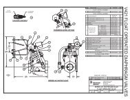
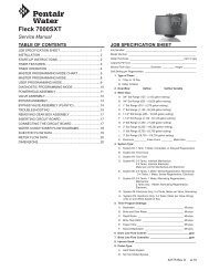
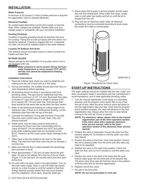
9. Place approximately 1" (25 mm) of water above the grid<br />
plate. If a grid is not utilized, fill to the top of the air check<br />
(Figure 1) in the salt tank. Do not add salt to the brine tank<br />
at this time.<br />
10. On units with a by-pass, place in by-pass position. Turn on<br />
the main water supply. Open a cold soft water tap nearby<br />
and let run a few minutes or until the system is free from<br />
foreign material (usually solder) that may have resulted<br />
from the installation. Once clean, close the water tap.<br />
Figure 1 <strong>Residential</strong> Air Check Valve<br />
START-UP INSTRUCTIONS<br />
60002 Rev E<br />
The water softener should be installed with the inlet, outlet, and<br />
drain connections made in accordance with the manufacturer’s<br />
recommendations, and to meet applicable plumbing codes.<br />
1. Turn the manual regeneraton knob slowly in a clockwise<br />
direction until the program micro switch lifts on top of the<br />
first set of pins. Allow the drive motor to move the piston to<br />
the first regeneration step and stop. Each time the program<br />
switch position changes, the valve will advance to the next<br />
regeneration step. Always allow the motor to stop before<br />
moving to the next set of pins or spaces.<br />
NOTE: For electronic valves, please refer to the manual<br />
regeneration part of the timer operation section.<br />
If the valve came with a separate electronic<br />
timer service manual, refer to the timer<br />
operation section of the electronic timer service<br />
manual.<br />
2. Position the valve to backwash. Ensure the drain line flow<br />
remains steady for 10 minutes or until the water runs clear<br />
(see above).<br />
3. Position the valve to the brine / slow rinse position. Ensure<br />
the unit is drawing water from the brine tank (this step may<br />
need to be repeated).<br />
4. Position the valve to the rapid rinse position. Check the<br />
drain line flow, and run for 5 minutes or until the water runs<br />
clear.<br />
5. Position the valve to the start of the brine tank fill cycle.<br />
Ensure water goes into the brine tank at the desired rate.<br />
The brine valve drive cam will hold the valve in this position<br />
to fill the brine tank for the first regeneration.<br />
6. Replace control box cover.<br />
7. Put salt in the brine tank.<br />
NOTE: Do not use granulated or rock salt.<br />
2 • JA12 <strong>Fleck</strong> <strong>2510</strong> & <strong>2510</strong> <strong>Econominder</strong>