GENERATOR

Create successful ePaper yourself
Turn your PDF publications into a flip-book with our unique Google optimized e-Paper software.
Portable Generator Familiarization & Troubleshooting Guide<br />
Section 3 • Generator Diagnostics and Adjustments<br />
XL&MC Generators, 8000-10000<br />
Watt<br />
Refer to Figure 3.4.<br />
Test 1: — Check (AC) Frequency and Voltage<br />
Connect an accurate (AC) frequency meter across the two<br />
parallel blades of one of the panel 120VAC receptacles.<br />
• Start the engine and let it stabilize.<br />
Read the (AC) frequency.A frequency reading of 61-63<br />
Hertz should be obtained.<br />
With the generator engine running:<br />
• Connect the VOM test probes across the parallel blades<br />
of the panel 120VAC receptacles.A reading of<br />
approximately 130-140VAC should be indicated.<br />
If voltage checks as specified:<br />
• Discontinue test.<br />
Test 2: — Check Idle Control Board Input<br />
Using a digital volt meter set to the VDC scale,<br />
• Connect the positive test lead to pin J2 on the idle<br />
control circuit board. Connect the negative test lead to<br />
J3 on the idle control circuit board. Pin J3 is the ground<br />
terminal of the board (Figure 3.5).<br />
If the unit does produce (AC,) but (DC) voltage is not<br />
present at pins J2 and J3, check for a failure in the battery<br />
charge circuit of the generator.<br />
Test 3: — Check Idle Control Switch Operation<br />
Remove wires 83 and 84 from the idle control board. Set a<br />
VOM to measure ohms. Connect the meter test leads to<br />
wires 83 and 84.Turn the idle switch ON.A reading of less<br />
than 0.3 ohms should be measured.Turn the idle switch<br />
OFF.A reading of “Infinity” should be measured.<br />
Test 4: — Check Idle Control Board Outputs<br />
Using a digital volt meter set to the “DC Volts” scale,<br />
• Connect the negative test lead to pin J3 on the idle<br />
control circuit board.<br />
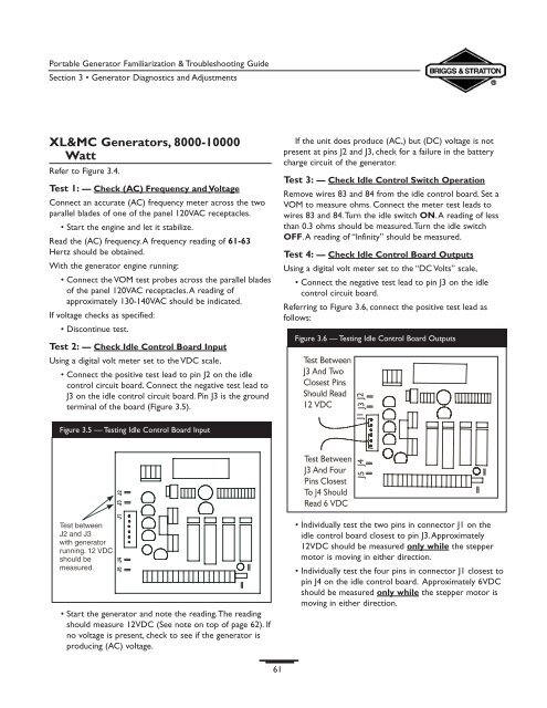
Referring to Figure 3.6, connect the positive test lead as<br />
follows:<br />
Figure 3.6 — Testing Idle Control Board Outputs<br />
Figure 3.5 — Testing Idle Control Board Input<br />
• Start the generator and note the reading.The reading<br />
should measure 12VDC (See note on top of page 62). If<br />
no voltage is present, check to see if the generator is<br />
producing (AC) voltage.<br />
• Individually test the two pins in connector J1 on the<br />
idle control board closest to pin J3.Approximately<br />
12VDC should be measured only while the stepper<br />
motor is moving in either direction.<br />
• Individually test the four pins in connector J1 closest to<br />
pin J4 on the idle control board. Approximately 6VDC<br />
should be measured only while the stepper motor is<br />
moving in either direction.<br />
61