GENERATOR

You also want an ePaper? Increase the reach of your titles
YUMPU automatically turns print PDFs into web optimized ePapers that Google loves.
Portable Generator Familiarization & Troubleshooting Guide<br />
Section 3 • Generator Diagnostics and Adjustments<br />
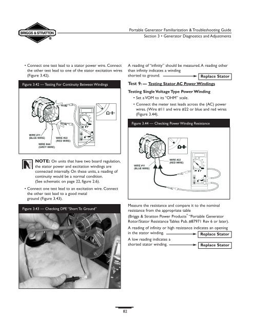
• Connect one test lead to a stator power wire. Connect<br />
the other test lead to one of the stator excitation wires<br />
(Figure 3.42).<br />
Figure 3.42 — Testing For Continuity Between Windings<br />
A reading of “infinity” should be measured.A reading other<br />
than infinity indicates a winding<br />
shorted to ground.<br />
Replace Stator<br />
Test 9:— Testing Stator AC Power Windings<br />
Testing Single Voltage Type Power Winding<br />
• Set a VOM to its “OHM” scale.<br />
• Connect the meter test leads across the (AC) power<br />
wires. (Wire #11 and wire #22 or blue and red wires<br />
(Figure 3.44).<br />
Figure 3.44 — Checking Power Winding Resistance<br />
NOTE: On units that have two board regulation,<br />
the stator power and excitation windings are<br />
connected internally. On these units, a reading of<br />
continuity would be a normal condition.<br />
(See schematic on page 22, figure 2.6).<br />
• Connect one test lead to an excitation wire. Connect<br />
the other test lead to a good metal<br />
ground (Figure 3.43).<br />
Figure 3.43 — Checking DPE “Short To Ground”<br />
Measure the resistance and compare it to the nominal<br />
resistance from the appropriate table<br />
(Briggs & Stratton Power Products ® “Portable Generator<br />
Rotor/Stator Resistance Tables Pub. #87971 Rev 6 or later).<br />
A reading of infinity or high resistance indicates an opening<br />
in the stator winding.<br />
Replace Stator<br />
A low reading indicates a<br />
shorted stator winding.<br />
Replace Stator<br />
82