GENERATOR

Create successful ePaper yourself
Turn your PDF publications into a flip-book with our unique Google optimized e-Paper software.
Portable Generator Familiarization & Troubleshooting Guide<br />
Section 4 • Generator Assemblies<br />
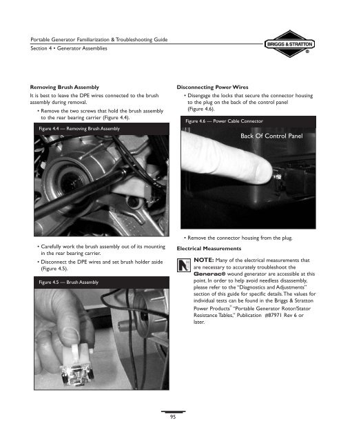
Removing Brush Assembly<br />
It is best to leave the DPE wires connected to the brush<br />
assembly during removal.<br />
• Remove the two screws that hold the brush assembly<br />
to the rear bearing carrier (Figure 4.4).<br />
Figure 4.4 — Removing Brush Assembly<br />
Disconnecting Power Wires<br />
• Disengage the locks that secure the connector housing<br />
to the plug on the back of the control panel<br />
(Figure 4.6).<br />
Figure 4.6 — Power Cable Connector<br />
Back Of Control Panel<br />
• Carefully work the brush assembly out of its mounting<br />
in the rear bearing carrier.<br />
• Disconnect the DPE wires and set brush holder aside<br />
(Figure 4.5).<br />
Figure 4.5 — Brush Assembly<br />
• Remove the connector housing from the plug.<br />
Electrical Measurements<br />
NOTE: Many of the electrical measurements that<br />
are necessary to accurately troubleshoot the<br />
Generac® wound generator are accessible at this<br />
point. In order to help avoid needless disassembly,<br />
please refer to the “Diagnostics and Adjustments”<br />
section of this guide for specific details.The values for<br />
individual tests can be found in the Briggs & Stratton<br />
Power Products ® “Portable Generator Rotor/Stator<br />
Resistance Tables,” Publication #87971 Rev 6 or<br />
later.<br />
95