GENERATOR

Create successful ePaper yourself
Turn your PDF publications into a flip-book with our unique Google optimized e-Paper software.
Portable Generator Familiarization & Troubleshooting Guide<br />
Section 3 • Generator Diagnostics and Adjustments<br />
Troubleshooting Sincro® Wound<br />
Generators (Brushless Type)<br />
Refer to Figure 3.46<br />
Test 1: — Check (AC) Frequency and Voltage<br />
Connect an accurate (AC) frequency meter across the two<br />
parallel blades of one of the panel 120VAC receptacles.<br />
• Start the engine and let it stabilize.<br />
Read the (AC) frequency.A frequency reading of 61-63<br />
Hertz should be obtained.<br />
If frequency is not within specifications:<br />
• Consult the appropriate engine service manual for<br />
adjustment.<br />
With the generator engine running, connect the VOM test<br />
probes across the parallel blades of the panel 120VAC<br />
receptacles.A reading of approximately 130-140VAC should<br />
be indicated.<br />
If voltage checks as specified:<br />
• Discontinue test.<br />
If voltage reading is zero:<br />
• Go to Test 2:“Flash The Field.”<br />
If voltage reading is low:<br />
• Go to Test 3:“Check The Rotor.”<br />
Test 2: — Flash The Field<br />
To restore magnetism in a generator having a capacitor<br />
excitation system, an energizing cord may be made locally<br />
(Figure 3.47).<br />
Figure 3.47 — Energizing Cord<br />
• Run the engine for 10 seconds, then shut the engine<br />
OFF.<br />
• Unplug the energizing cord from the generator<br />
receptacle and from the wall receptacle.<br />
• Restart the generator engine and check (AC) voltage.<br />
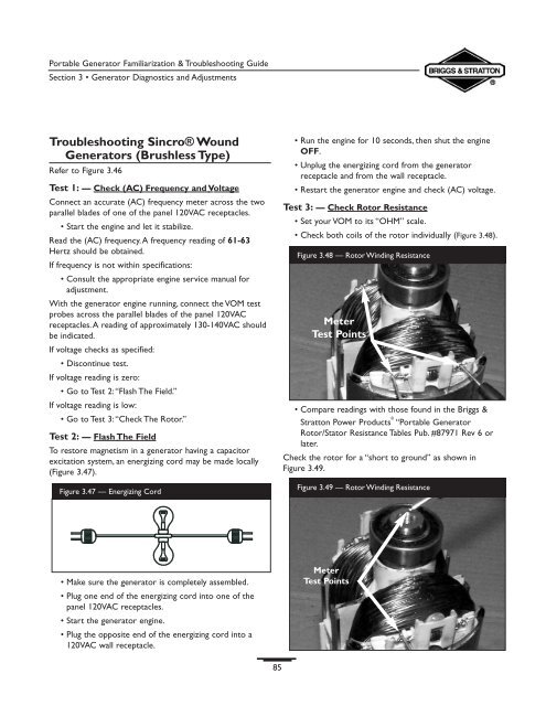
Test 3: — Check Rotor Resistance<br />
• Set your VOM to its “OHM” scale.<br />
• Check both coils of the rotor individually (Figure 3.48).<br />
Figure 3.48 — Rotor Winding Resistance<br />
Meter<br />
Test Points<br />
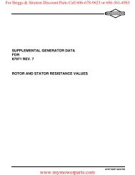
• Compare readings with those found in the Briggs &<br />
Stratton Power Products ® “Portable Generator<br />
Rotor/Stator Resistance Tables Pub. #87971 Rev 6 or<br />
later.<br />
Check the rotor for a “short to ground” as shown in<br />
Figure 3.49.<br />
Figure 3.49 — Rotor Winding Resistance<br />
• Make sure the generator is completely assembled.<br />
• Plug one end of the energizing cord into one of the<br />
panel 120VAC receptacles.<br />
• Start the generator engine.<br />
• Plug the opposite end of the energizing cord into a<br />
120VAC wall receptacle.<br />
Meter<br />
Test Points<br />
85