TP 12KC-D Instruction Manual - Auto Body Toolmart
TP 12KC-D Instruction Manual - Auto Body Toolmart
TP 12KC-D Instruction Manual - Auto Body Toolmart

Create successful ePaper yourself
Turn your PDF publications into a flip-book with our unique Google optimized e-Paper software.
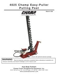
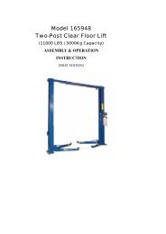
Model No. <strong>TP</strong><strong>12KC</strong>-D<br />
12,000 lb Capacity Two Post<br />
Symmetric Lift<br />
PLEASE READ ENTIRE MANUAL BEFORE<br />
INSTALLATION OF THIS LIFT<br />
1
Model Number<br />
<strong>TP</strong><strong>12KC</strong>-D<br />
Capacity<br />
12,000 lbs.<br />
Lifting height 5.5" - 72"<br />
with adapters 79.625"<br />
Height overall 165"<br />
Width between columns 122"<br />
Drive through 109"<br />
Width overall 151.125"<br />
Arm extension 37.5" - 57"<br />
Power pack<br />
2hp 220vac<br />
Shipping weight<br />
2235 lbs.<br />
2
INSTALLATION INSTRUCTIONS<br />
Choosing A Location<br />
• Use architects' plans when available. See Floor Layout on Page 6 for typical layout<br />
of the12000# inverted cylinder model.<br />
• Two Post Lifts require a minimum ceiling height of 3” higher than the overall height<br />
of the lift being installed. For the <strong>TP</strong><strong>12KC</strong>-D this will be 168” (14').<br />
• The Steel Reinforced Concrete floor must be level, have a minimum thickness of 4<br />
inches, and retain a commercial rating of 3500 psi. The concrete must be cured for a<br />
minimum of 28 days.<br />
• Before making a Final Decision, consider the amount of workday traffic flowing in<br />
and around the location you have chosen. Also consider the amount of room out front<br />
of the lift for a workbench or diagnostic equipment. There may also be some future<br />
building plans to consider. Are you satisfied with your selection?<br />
3
Important General Information<br />
1. There are numerous blends and mixes and additives these days for concrete. All of<br />
these work well when used in the proper application. However, years of experience have<br />
shown that nothing beats a properly cured, steel reinforced concrete slab for this<br />
application. Another thing to watch is additives that claim to harden the concrete faster or<br />
reduce the cure time. Again, these things have their place, but not in this application! A<br />
steel rod or mesh reinforced slab cured 28-30 days with the slab kept properly hydrated<br />
gives the best results.<br />
2. Checking bolts for tightness to some people means that once a week they grab a<br />
wrench and go around yanking a quarter of a turn on every nut and bolt they see. This is,<br />
of course, not the proper way of handling any bolt, especially the stress anchor used to<br />
anchor your lift. When the anchors are installed, they must be torqued with a torque<br />
wrench to 150 foot-pounds initially. After a period of time, they will loosen up some.<br />
This is normal. When checking the anchors just put a wrench on them and “feel of them”<br />
or apply a small amount of torque to the bolt. If it is tight, it is good to go. If it is loose,<br />
get a torque wrench and tighten it to 60-90 foot-pounds.<br />
3. The lift is not designed for an outdoor installation because of the possible damage and<br />
degradation to the hydraulics and the electrical components caused by direct exposure to<br />
the elements. If the unit is installed in a building or outbuilding with a floor that is<br />
anything other than the recommended concrete floor, a pad can be poured. The size and<br />
construction of the pad can vary depending on the soil conditions and the local weather<br />
conditions. It is recommended that each of these situations be handled separately by a<br />
local engineer.<br />
4. Never place a lift in a pit or depression in a garage area or any environment where<br />
gasoline is around. Gasoline fumes tend to gather at the floor and low areas, so the lift<br />
must be mounted on the main floor of the building and not in the basement or a pit.<br />
5. Always remember that your lift is rated at 12000 pounds. This means that the lift will<br />
safely and reliably lift a load of 12000 pounds as long as that load is evenly distributed on<br />
all four arms. If the load is offset or unevenly distributed, then one post can actually be<br />
operating at a load greater than 12000# and the lift can be overloaded with less than the<br />
rated load. So the lift load rating is 12000 pounds or 3000 pounds per arm.<br />
Positioning the Post (Columns)<br />
4
Carefully examine the packed unit for damage before unpacking. Any claims for damage<br />
should be filed with the freight carrier at delivery. Unbolt the package being careful to<br />
save the bolts and use them to reinstall the top caps after unpacking the lift. Place posts in<br />
bay using dimensions shown in Floor Layout (Figure 1). The bases must be square with<br />
the layout lines as shown. It is recommended that the extensions be mounted to the posts<br />
before standing them up. You will need a considerable amount of help standing up these<br />
posts.<br />
Drilling and Anchoring<br />
A. Drill 3/4” x 5-1/2” (minimum depth) holes in the concrete floor using the holes in the<br />
base plates as guides. Drill the holes perpendicular to the surface, being sure not to<br />
enlarge them by allowing the drill to wobble. Do not ream-out the holes. (See Anchoring<br />
<strong>Instruction</strong>s, Figure 2). Be careful when drilling the holes, the posts can tip over.<br />
B. Blow all of the dust and debris from the holes, then clean around the openings with<br />
a wire brush. A clean hole will improve the prospect of solid anchoring.<br />
c. It is recommended that the lift to be located 10’ – 12’ from the nearest obstruction<br />
in front of the lift and 2’ – 3’ from the nearest obstruction on the sides of the lift.<br />
2. To install Anchor:<br />
A. Assemble the washer and nut onto the anchor bolt with nut just below impact section<br />
of bolt.<br />
B. With a hammer, carefully tap the anchor bolt into the concrete until the washer is<br />
resting on the base of the column. DO NOT DAMAGE THE NUT OR THREADS!<br />
C. Before tightening the nuts, level and plumb the columns, using the shims provided.<br />
Note: If more than 1/2” of shims is required to level the post, Do Not Use the<br />
Anchors supplied with this lift. It will be necessary to purchase longer anchors<br />
for your application. The brand of anchor recommended is the Hilti Kwik-Bolt.<br />
D. When columns are level and plumb, tighten the nuts with a Torque Wrench to 150 ftlb.<br />
If anchors do not tighten to 150 ft-lbs in existing floor, replace concrete under<br />
each post with a 6’ x 6’ x 10” thick pad keyed into and flush with the existing floor.<br />
Concrete must be 3500 PSI minimum.<br />
5
NOTE: NEVER USE AN IMPACT WRENCH TO TIGHTEN ANCHOR BOLTS!<br />
Attaching The Overhead Beam and Shut-Off Bar<br />
1. The overhead beam is attached to the extensions at the ends with eight nuts and bolts.<br />
See picture.<br />
2. The cable sheaves must assembled onto the shafts with the spacers supplied as shown<br />
in the picture prior to attaching the overhead channel.<br />
3.To Install the Shut-Off Bar<br />
Attach the shutoff bar and switch housing to the underside of the overhead beam. Attach<br />
single bolt and bar first, then install switch housing.<br />
4. Run electrical cord into the beam and back out of the column using provided bulk<br />
head fittings.<br />
6
Attaching the Air Actuator<br />
1. Locate offside air cylinder and insert 6mm hose into PTC fitting.<br />
2.Run air hose up and over top of column, running through top side of overhead beam<br />
and down to main side lock assembly.<br />
3.Connect air hose to provided PTC 3-way fitting, cut to size a piece of air hose and run<br />
to main side air cylinder PTC fitting. Remaining hose will be connected from 3-way<br />
fitting to palm actuated air release button valve.<br />
4.Attach palm valve to steel bracket on side of column.<br />
5.Connect shop air to palm valve. We recommend using leftover hose and NPT fitting<br />
(not included).<br />
Installing the Equalizer Cables<br />
A. <strong>Manual</strong>ly lift both carriages to about waist height. Be sure they are the same height<br />
and on the same latch location on the carriage.<br />
7
B. Install the Equalizer Cables using the Routing for the lift as shown in the picture. The<br />
cables should be taught, but no too tight. Be certain to tighten the jam nuts.<br />
Cables are routed identically the same on both columns. Cable on right is routed down<br />
and around the sheave then up and over the overhead beam. Then routed down to the top<br />
of the carriage.<br />
Be sure cables are seated securely on the sheaves.<br />
8
Power Unit Placement and Connection of the Hydraulic Hoses<br />
1. Remove the power unit from the box and locate the mounting hardware. For easy<br />
mounting, place two bolts through the middle slots on the power unit mounting plate and<br />
start the nuts on them. Then lift the unit up and slide the unit into position while guiding<br />
the bolts into the slots on the bracket from the top. Install the other two bolts and tighten<br />
securely.<br />
2. Install longest hose first. One end has 90 degree fitting that hooks to bottom of the<br />
offside cylinder and then route hose through the leg gusset.<br />
DO NOT OVER TIGHTEN FITTINGS!!.<br />
3. Route the hose up the column installing the hose clamps as you go. Then follow<br />
across the outside of the overhead beam (installing hose clamps as you go). Down the<br />
main side column towards your power unit.<br />
4. Run hose through the top of your power unit bracket until the end of your hose comes<br />
through the bottom of the bracket.<br />
5. Install power unit elbow fitting into the port that has the red plastic cap located on the<br />
left side of your power unit. Connect shortest hydraulic hose to the elbow fitting.<br />
Connect the T fitting to the shortest hose and then connect overhead hose to the T<br />
fitting.<br />
6. Connect medium length hose with 90 degree fitting to main side cylinder and thread<br />
through leg gussets. Run the hose up to the T fitting and tighten. See pictures –<br />
9
NOTE: DO NOT OVER-TIGHTEN THE HYDRAULIC HOSE<br />
CONNECTIONS!<br />
Attaching the Swing Arms and Arm Restraints<br />
1. Locate the arms, arm pivot pins, and hardware. Place the arm clevis end into the clevis<br />
on the carriage. Place thrust washer on bottom side of carriage clevis.<br />
2. Slide the pivot pins through the arms and carriage until it bottoms out.<br />
3. Check the operation of the arm restraints. Make sure they engage and disengage<br />
properly.<br />
10
Electrical Connection<br />
NOTE: WE STRONGLY RECOMMEND THAT YOU USE A<br />
LICENSED, PROFESSIONAL ELECTRICIAN TO INSTALL<br />
THE POWER TO YOUR TWO POST LIFT!<br />
Filling the Hydraulic Fluid Tank<br />
Remove the vent-cap from the top of the Hydraulic Fluid Tank attached to the Power<br />
Unit. Using a funnel, carefully pour in the Hydraulic Fluid (approximately 12 quarts)<br />
until fluid gets near the top of the tank. Replace the vent-cap.<br />
***********************************************<br />
We Recommend Using One of the Following Fluids:<br />
Dextron III Non-Detergent<br />
AW #32 Hydraulic Oil<br />
***********************************************<br />
11
Bleeding the System<br />
1. Actuate the power unit and hold the button until both carriages lift off the locks.<br />
2. Carefully loosen the bleeding screw at top end of the cylinder and allow the trapped<br />
air to escape. CAUTION! The air in the cylinders is under pressure. Protect your<br />
eyes and cover the end of the cylinder with a rag because oil may spray out of the<br />
cylinder.<br />
3. Repeat the process for the other cylinder.<br />
CAUTION: DO NOT OVER TIGHTEN THE BLEED PLUG<br />
Adjusting the Equalizer Cables to Synchronize Carriages<br />
Raise and lower the lift several times while listening to the clicking of the safety locks<br />
in each column. If the safety locks are not clicking in unison (at the same time),<br />
determine which carriage is running behind, and tighten (just a few turns) the<br />
adjustment bolt on the opposite side. When the cables are properly adjusted, they<br />
should feel fairly tight.<br />
Final Assembly<br />
1. Using the adhesive cable anchors and cable ties, fasten the overhead switch cord and<br />
the air lines to the posts.<br />
2. Install lock release covers over both assemblies with provided screws.<br />
3. Check all nuts and bolts, making sure they are tight. Check the jam nuts on the<br />
equalizer cables for tightness.<br />
4. Check all of the hydraulic fittings for possible leaks. Check all the fittings for<br />
proper tightness.<br />
5. Make sure the Carriages are synchronized.<br />
6. Make sure post are greased.<br />
7. Place a vehicle on the lift (see operating section for instructions below for to the safe<br />
and proper way to lift a vehicle), raising the vehicle until it clears the floor. Lower the<br />
lift all the way to the floor and recheck all the anchor bolts. Raise the vehicle all the<br />
way to the top and lower all the way to the floor several times. This procedure will<br />
ready the lift for continued operation.<br />
OPERATION<br />
1. Center the vehicle left and right between the posts.<br />
12
2. Position the swivel pads under the frame of the car at the proper lifting points.<br />
(To find the proper lifting points, consult the vehicle’s service manual or other<br />
approved publication.)<br />
3. Push the up button and raise the lift until the swivel pads make contact with lifting<br />
points.<br />
4. Check all swivel pads to make certain all adapters are making full and proper<br />
contact. NEVER go under a vehicle unless all adapters are in secure contact with<br />
the vehicle.<br />
5. Raise the vehicle approximately 2 feet and check the stability by rocking the<br />
vehicle. Make sure vehicle weight is centered. Do not raise if weight is front or<br />
tail heavy.<br />
6. Raise the vehicle to the desired height and lower on the carriage latches. NEVER<br />
go under a vehicle unless the carriage latches are engaged. If any heavy parts are<br />
to be removed, use a set of high stands for added safety.<br />
7. Before lowering, check the area under the vehicle to be sure it is clear. Raise lift<br />
slightly, pull the Latch Release Handle and hold, then pull down on the lowering<br />
release arm and lower SLOWLY. Keep feet clear.<br />
8. After lowering, rotate the swing arms back out of the way.<br />
MAINTENANCE SCHEDULE<br />
DAILY<br />
1. Always keep bolts tight.<br />
2. Check for oil leaks.<br />
MONTHLY:<br />
1. Re-torque the anchor bolts if necessary. (See CAUTION! below)<br />
2. Lubricate chains/cables with spray lubricant.<br />
3. Check all connectors, bolts and pins to insure proper mounting.<br />
4. Make a visual inspection of all hydraulic hoses and lines for possible wear or<br />
interference.<br />
!<br />
13
ALL ANCHOR BOLTS SHOULD ALWAYS BE TIGHT. Check the bolts periodically<br />
and tighten if necessary to 60-90 ft.-lbs. after the bolts have been set at installation. If any<br />
of the bolts do not function for any reason, the lift should be shut down until the bolt has<br />
been replaced.<br />
EVERY SIX (6) MONTHS:<br />
1. Make a visual inspection of all moving parts for possible wear, interference or damage.<br />
2. Check all pulleys for proper lubrication. If pulleys seem to be dragging during lifting<br />
or lowering, lightly oil the axle.<br />
3. Check and adjust as necessary, equalize tension to insure level lifting.<br />
4. Check columns for plumbness.<br />
5. Check fluid level of power unit.<br />
6. Lube columns.<br />
TROUBLESHOOTING THE LIFT<br />
14
1. Motor does not run: A. Breaker or fuse blown.<br />
B. Motor thermal overload tripped.<br />
C. Defective UP switch. Replace.<br />
D. Faulty wiring connections. Call<br />
electrician.<br />
E. Check the overhead shut-off bar<br />
operation.<br />
It could be faulty or stuck-thus<br />
holding the switch open.<br />
2. Motor runs but lift will not raise: A. Trash is under check valve. Push<br />
handle down and push the UP button at the<br />
same time. Hold for 15 seconds. This should<br />
flush the system.<br />
B. Remove the check valve cover with<br />
an Allen wrench. Clean the ball and seat and<br />
replace the cover.<br />
C. Oil level low. Oil level should be just<br />
under the vent cap port when the lift is<br />
down.<br />
3.Motor runs but lift picks up partial<br />
load only: A. Faulty relief valve. Replace.<br />
B. Oil is coming out of breather on<br />
cylinder.<br />
C. Seals damaged.<br />
4. Oil blows out of breather: A. Oil reservoir overfilled.<br />
B. Lift lowered too quickly while under<br />
a heavy load.<br />
5. Motor hums and will not run: A. Impeller fan cover is dented in. Take<br />
off and<br />
straighten.<br />
B. Faulty wiring - Call an Electrician.<br />
C. Bad capacitor - Call an Electrician.<br />
D. Low voltage - Call an Electrician.<br />
E. Lift over loaded.<br />
6. Lift jerks up and down: A. Cables are too loose - (See Adjusting<br />
The Equalizer Cables).<br />
B. Air in system - bleed the system.<br />
(See Installation <strong>Instruction</strong>s - Bleeding the<br />
System<br />
15
ITEM DESCRIPTION QTY<br />
1 Column jointings 1<br />
2 Adjust washer 12<br />
3 Upset bolt 12<br />
4 Spindle 4<br />
5 Spindle 4<br />
6 Baffle ring 6<br />
7 Pin 2<br />
8 Spring 2<br />
9 Safety ass'y 2<br />
10 Cam 2<br />
11 Pin 2<br />
13 Elbow fitting joint 2<br />
14 Pin 4<br />
15 Pin 2<br />
16 Fitting joint 2<br />
17 Cylinder 2<br />
18 Cross beam parts 1<br />
19 Bolt 5<br />
20 Washer 9<br />
21 Pole 1<br />
22 Nut 5<br />
23 Sponge bush 1<br />
24 Rubber block 16<br />
25 Carriage 2<br />
26 Hydraulic cylinder 2<br />
26-1 Cylinder barrel 2<br />
*26-2 Dust ring 2<br />
26-3 Guide ring 2<br />
26-4 Fixed part for piston 2<br />
*26-5 O-ring 4<br />
26-6 Piston rod 2<br />
26-7 Limit ring 2<br />
*26-8 Guide ring 2<br />
*26-9 O-ring 2<br />
*26-10 Packing ring 2<br />
63 Pin 4<br />
64 Gear 4<br />
65 Pin 8<br />
66 Gear 4<br />
67 Rack spindle 4<br />
68 Spring 4<br />
69 Key ring 4<br />
70 Fitting joint 2<br />
71 Nut 8<br />
72 Washer 4<br />
73 Steel cable 2<br />
*74 O-Ring 1<br />
16
75 T fitting joint 1<br />
76 Fitting joint 1<br />
77 Plug 1<br />
28 Flat washer 104<br />
29 Nut 48<br />
30 Link plank 4<br />
31 Cap 2<br />
32 Bush 4<br />
33 Bush 2<br />
34 Wheel 6<br />
35 Spindle 2<br />
36 Vice column jointings 2<br />
37 Hoop 16<br />
38 Screw 16<br />
39 Screw 16<br />
40 Plate 1<br />
41 Switch cover 1<br />
42 Switch 1<br />
43 Cable 1<br />
44 Oil hose 1<br />
45 Oil hose 1<br />
46 T fitting joint 1<br />
47 Oil hose 1<br />
48 Flat washer 8<br />
49 Cover 2<br />
50 Elbow fitting joint 2<br />
51 Switch 1<br />
52 Power unit 1<br />
53 Column jointings 1<br />
54 Air hose 1<br />
55 Air hose 1<br />
56 Air hose 1<br />
57 T fitting joint 1<br />
58 Screw 12<br />
59 Rubber washer 4<br />
60 Salver jointing 4<br />
61 Flex arm 4<br />
63 Pin 4<br />
64 Gear 4<br />
65 Pin 8<br />
66 Gear 4<br />
67 Rack spindle 4<br />
68 Spring 4<br />
69 Key ring 4<br />
70 Fitting joint 2<br />
71 Nut 8<br />
72 Washer 4<br />
73 Steel cable 2<br />
*74 O-Ring 1<br />
17
75 T fitting joint 1<br />
76 Fitting joint 1<br />
77 Plug 1<br />
64 Gear 4<br />
65 Pin 8<br />
66 Gear 4<br />
67 Rack spindle 4<br />
68 Spring 4<br />
69 Key ring 4<br />
70 Fitting joint 2<br />
71 Nut 8<br />
72 Washer 4<br />
73 Steel cable 2<br />
*74 O-Ring 1<br />
75 T fitting joint 1<br />
76 Fitting joint 1<br />
78 Washer 4<br />
32<br />
33<br />
34<br />
35<br />
36<br />
A<br />
27<br />
28<br />
31<br />
29<br />
30<br />
29<br />
28<br />
27<br />
31<br />
37 38<br />
42<br />
39<br />
A<br />
40<br />
22<br />
43<br />
41<br />
17<br />
16<br />
18<br />
21<br />
20<br />
19<br />
B<br />
23<br />
24<br />
25<br />
26<br />
49<br />
22<br />
50<br />
39<br />
48<br />
45<br />
46<br />
47<br />
20 19<br />
26-11<br />
26-10<br />
44 26-9<br />
26-8<br />
26-5<br />
26-7<br />
26-1 26-6<br />
51<br />
52<br />
C<br />
13<br />
14<br />
11<br />
10<br />
9<br />
14<br />
15<br />
B<br />
8<br />
5<br />
7<br />
4<br />
6<br />
78<br />
69<br />
68<br />
70 47 71<br />
72<br />
67<br />
66<br />
73<br />
6<br />
34<br />
59<br />
60<br />
58<br />
53<br />
57<br />
44<br />
C<br />
54<br />
55<br />
56<br />
26-4<br />
26-3<br />
26-2<br />
26-5<br />
3<br />
63<br />
62<br />
61<br />
74 75 76<br />
77<br />
2<br />
1<br />
27<br />
28<br />
58<br />
18<br />
64