Champ Spider Frame Straightener - Auto Body Toolmart
Champ Spider Frame Straightener - Auto Body Toolmart
Champ Spider Frame Straightener - Auto Body Toolmart
- No tags were found...

You also want an ePaper? Increase the reach of your titles
YUMPU automatically turns print PDFs into web optimized ePapers that Google loves.
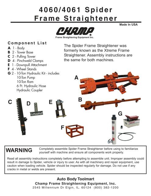
4060/4061 <strong>Spider</strong><strong>Frame</strong> <strong>Straightener</strong>Made In USAComponent ListA 1 - <strong>Body</strong>B 2 - Tower BaseC 2 - Pulling TowerD 4 - Pinchweld ClampsE 1 - Downpull AttachmentF 4 - Wheel StandsG 2 - 10-Ton Hydraulic Kit - includes10-Ton Pump10-Ton Ram6 Ft. Hydraulic HoseHydraulic Coupler<strong>Frame</strong> Straightening Equipment Inc.The <strong>Spider</strong> <strong>Frame</strong> <strong>Straightener</strong> wasformerly known as the Xtreme <strong>Frame</strong><strong>Straightener</strong>. Assembly instructions arethe same for both machines.AC D EBGFWARNINGCompletely assemble <strong>Spider</strong> <strong>Frame</strong> <strong>Straightener</strong> before using to familiarizeyourself with machine and ensure all components work properly.Read all assembly instructions completely before attempting to assemble unit. Improper assembly couldresult in damage to <strong>Spider</strong>, vehicle or injury to user. As with all machinery and repair equipment, usecaution when loading vehicle. <strong>Spider</strong> should be inspected regularly for damage. Do not use if anycracks in metal or welds are present.<strong>Auto</strong> <strong>Body</strong> <strong>Toolmart</strong><strong>Champ</strong> <strong>Frame</strong> Straightening Equipment, Inc.2545 Millennium Dr Elgin, IL. 60124 (800) 382-1200
4060 <strong>Spider</strong> <strong>Frame</strong> <strong>Straightener</strong>Assembly Instructions<strong>Spider</strong> <strong>Frame</strong> <strong>Straightener</strong> should be completely assembledbefore using to familiarize yourself with machine and ensure allcomponents work properly.<strong>Auto</strong> <strong>Body</strong> <strong>Toolmart</strong><strong>Champ</strong> <strong>Frame</strong> Straightening Equipment, Inc.760 Industrial Drive ~ Unit D ~ Cary, IL. 60013 (800) 382-1200
1 2Remove locking pin and swing out Clamp Arm.Install locking pin to lock Clamp Arm into placeInstall Pinchweld Clamps into Clamp Brackets.Insert Locking Pin to hold clamp into position.Height is adjustable.3 4Attach Pulling Tower to Tower Base withsupplied bolt. Tighten securely.Install Hydraulic Ram by screwing femaleend to Ram Coupler on Tower Base.67Remove Ram Coupler from Pulling Tower andscrew onto Hydraulic Ram. Attach RamCoupler to Pulling Tower using supplied bolt.Repeat steps for second Pulling Tower.Insert assembled Pulling Tower into each ofthe Six tower inserts. Lock into place withLocking Pin.
8 9Tower insertsThe middle insert is adjustable. Loosen Boltsand slide into desired position. Tighten boltssecurely.Install Down Pull attachment on to pullingtower by removing mounting bolts. Set DownPull onto Tower Base Reinstall mounting boltsand tighten securely.<strong>Auto</strong> <strong>Body</strong> <strong>Toolmart</strong><strong>Champ</strong> <strong>Frame</strong> Straightening Equipment, Inc.760 Industrial Drive ~ Unit D ~ Cary, IL. 60013 (800) 382-1200
Parts ListUpper Boom AttachmentThe following instructions apply only if you purchasedthe Upper Boom optionThe 4061 will include40604060 plus the followingparts for the overhead boom.• 1 - 10 Ton Pump - L• 1 - 10 Ton Ram - M• 1 - 6’ Hydraulic Hose - N• 1 - Hose Half Coupler - O• 2 - Post Ram Coupler - P• 1 - Overhead Boom - Q• 1 - Nuts, Bolts & Pin Assortment - RMLQPNOR
Attaching theUpper Boom1. 2.Attach male Upper Boom tofemale end of hydraulic ramAttach to upper Post couplerconnection and tighten bolt securelyAttach female coupler to3. male end of hydraulic ram 4.Position upper boom into place onPost. Bolt into place and tighten nutsecurely.
5.Attach ram coupler toupper boomYour <strong>Spider</strong> <strong>Frame</strong> <strong>Straightener</strong> is nowassembled with Upper Boom and ready to use.<strong>Auto</strong> <strong>Body</strong> <strong>Toolmart</strong><strong>Champ</strong> <strong>Frame</strong> Straightening Equipment, Inc.760 Industrial Drive ~ Unit D ~ Cary, IL. 60013 (800) 382-1200
4060 <strong>Spider</strong> <strong>Frame</strong> <strong>Straightener</strong>Usage Instructions<strong>Spider</strong> <strong>Frame</strong> <strong>Straightener</strong> should be completely assembledbefore using to familiarize yourself with machine and ensure allcomponents work properly.<strong>Auto</strong> <strong>Body</strong> <strong>Toolmart</strong><strong>Champ</strong> <strong>Frame</strong> Straightening Equipment, Inc.760 Industrial Drive ~ Unit D ~ Cary, IL. 60013 (800) 382-1200
12Raise vehicle and lower onto suppliedvehicle stands.3 4Remove Pinchweld Clamp Brackets.Fold Bracket Arms against <strong>Body</strong> and lockinto place with Locking Pin5 6Position <strong>Spider</strong> under vehicleSwing Bracket arms back out. ReinstallPinchweld Clamp Brackets & PinchweldClamps.Raise vehicle to remove wheel stands andlower into Pinchweld Clamps
7 8Tighten Pinchweld Clamps securely ontovehicle pinchwelds.Tighten Pinchweld Brackets securely toBracket Arms.9 10Vehicle is now attached to <strong>Spider</strong> andyou are ready to attach Pulling Towers.Insert tower into desired tower insert andlock into place with locking pin.Wrap chain around Pulling Tower and lock intoplace using chain lock or pulling hook. Chainheight is adjustable by positioning chain againstthe desired lock on tower.Each pulling tower has two swivels for extended reach. Removelocking pin, swivel into desired position and reinsert locking pin.