TP11KAC-D Instruction Manual - Auto Body Toolmart
TP11KAC-D Instruction Manual - Auto Body Toolmart
TP11KAC-D Instruction Manual - Auto Body Toolmart

You also want an ePaper? Increase the reach of your titles
YUMPU automatically turns print PDFs into web optimized ePapers that Google loves.
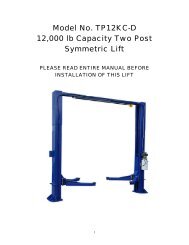
Model 165948Two-Post Clear Floor Lift(11000 LBS / 5000Kg Capacity)ASSEMBLY & OPERATIONINSTRUCTION(FIRST EDITION)
165948 Two Post Lift Installation and Owners <strong>Manual</strong>Table of contents [u1]:-- Important Information-- Section 1 Owner’s <strong>Manual</strong>Safety <strong>Instruction</strong>sMonthly MaintenanceTroubleshooting-- Section 2 Installation <strong>Instruction</strong>sTools Required of InstallationProcedure-- Section 3 Parts BreakdownDetailed Views & Parts ListImportant Information1. Read this manual thoroughly before installing, operating, or maintaining this lift.2. This lift is designed for indoor use only, and should not be installed in a pit or depression.3. The floor on which the lift is to be installed must be 4-¼” inch minimum thicknessconcrete, with a minimum compressive strength of 3000 psi, and reinforcedwith steel bar.4. The lifts have specific electrical requirements as described in the Installation <strong>Instruction</strong>ssection of this manual.5. This lift has a minimum ceiling height requirement as described in the Installation <strong>Instruction</strong>ssection of this manual.6. Failure by the owner to provide the recommended shelter, mounting surface,electrical supply, and ceiling height could result in unsatisfactory lift performance,property damage, or personal injury.2
165948 Two Post Lift Installation and Owners <strong>Manual</strong>Section 1Owner’s <strong>Manual</strong>Safety <strong>Instruction</strong>s:1. Do not raise a vehicle on the lift until the installation is completed as described in this manual.2. Anyone who will be in the vicinity of the lift when it is in use are recommended to read thefollowing publications:a. “INSTALLATION AND OWNERS MANUAL”,b. “LIFTING IT RIGHT”, ALI SM93-1c. “AUTOMOTIVE LIFT SAFETY TIPS”, ALI-ST90.d. “VEHICLE LIFTING POINTS FOR FRAME ENGAGING LIFTS”,ALI/LP-GUIDE.e. “SAFETY REQUIREMENTS FOR OPERATION, INSPECTION, ANDMAINTENANCE’, ANSI/ALI ALOIM-1994.3. Technicians should be trained to use and care for the lift by familiarizing themselves with thepublications listed above. The lift should never be operated by an untrained person.4. Always position the arms and adapters properly out of the way before pulling the vehicle into, orout of the bay. Failure to do so could damage the vehicle and/or the lift.5. Do not overload the lift. The capacity of the lift is shown on cover of this document and onthe lift’s serial number tag6. Positioning the vehicle is very important. Only trained technicians should position the vehicle onthe lift. Never allow anyone to stand in the path of the vehicle as it is beingpositioned and never raise vehicle with passengers inside.7. Position the arms to the vehicle manufacturer’s recommended pickup points. Raise the lift untilcontact is made with the vehicle. Make sure that the arms have properly engaged the vehiclebefore raising the lift to a working height.8. Keep everyone clear of the lift when the lift is moving, the locking mechanism is disengaged, orthe vehicle is in danger of falling.9. Unauthorized personnel should never be in the shop area when the lift is in use.10. Inspect the lift daily. The lift should never be operated if it has damagedcomponents, or is malfunctioning. Only qualified technicians should service the lift.Replace damaged components with manufacturer’s parts, or equivalent.3
165948 Two Post Lift Installation and Owners <strong>Manual</strong>11. Keep the area around the lift clear of obstacles.12. Never override the self-returning lift controls.13. Use safety stands when removing or installing heavy vehicle components.14. Avoid excessive rocking of the vehicle when it is on the lift.15. To reduce the risk of personal injury, keep hair, loose clothing, fingers, and all body parts awayfrom moving parts.16. To reduce the risk of electric shock, do not use the lift when wet, do not expose the lift to rain.17. To reduce the risk of fire, do not operate equipment in the vicinity of open containers offlammable liquids (gasoline).18. Use the lift only as described in this manual, use only manufacturer’s recommendedattachments.19. Unusual vehicles, such as limousines, RV’s, and long wheelbase vehicles,may not be suitable for lifting on this equipment. If necessary, consult with themanufacturer or the manufacturer’s representative.20. The troubleshooting and maintenance procedures described in this manual can be done by thelift’s owner/employer. Any other procedure should only be performed by trained lift servicepersonnel. These restricted procedures include, but are not limited to, thefollowing: cylinder replacement, carriage and safety latch replacement, legreplacement, overhead structure replacement.21. Anyone who will be in the vicinity of the lift when it is in use should familiarize themselves withfollowing Caution, Warning, and Safety related decals supplied with this lift, and replace them ifthe are illegible or missing.Monthly Maintenance:1. Lubricate the four inside corners of the legs with heavy duty bearing grease.2. With lift lowered check the hydraulic fluid level. If necessary add oil as described in theInstallation <strong>Instruction</strong> section of this manual3. Check carriage latch synching: Latches should click at the same time. Ifnecessary adjust equalization cables as described in the Installation <strong>Instruction</strong> section of thismanual.4
165948 Two Post Lift Installation and Owners <strong>Manual</strong>4. Check tightness of all bolts.5. Check anchor bolt tightness. If the anchor bolts are loose, they should bere-torqued to 90ft/lbs.Check the nuts for tightness every week for the first month, and every monthafterwards.6. Replace worn or broken parts with lift manufacturer’s parts, or their equivalent.Troubleshooting:1. The power unit does not run:a. Check electrical supply breaker, or fuse.b. Check for activation of the travel limit switch by a tall vehicle.c. Check micro-switch and connections in motor control box.d. Check voltage to the motor.e. Check micro-switch and connections in the overhead switch box.2. The power unit runs but does not raise the lift:a. Check the oil level.b. Check that the lowering valve is not stuck open.c. Check the connections and components on the suction side of the pump.3. The power unit raises the lift empty, but will not lift a vehicle:a. Make sure the vehicle is not above the rated capacity of the lift.b. Make sure the vehicle is positioned properly.c. Clean the lowering valve by running the power unit for 30 seconds while holding thelowering valve open.d. Check the motor voltage.4. Lift drifts down:a. Check for external leaks.b. Clean the lowering valve by running the power unit for 30 seconds while holding the loweringvalve open. Repeat this procedure three times.c. Clean the check valve seat.5. Slow Lifting and/or oil foaming up:a. Check that oil used meets the specification in the Installation <strong>Instruction</strong> section of this5
165948 Two Post Lift Installation and Owners <strong>Manual</strong>manual.b. Tighten all suction line fittings.6. Anchors continually work loose:a. If holes were drilled too large relocate the lift per the Installation <strong>Instruction</strong> section of thismanual.b. Floor is not sufficient to provide the necessary resistance, remove an area of concrete andrepour as described in the Installation <strong>Instruction</strong> section of this manual.7. Lift does not raise and lower smoothly:a. Reposition vehicle for a more even weight distribution.b. Check the four inside corners of the two legs for roughness. Any rust or burrs must beremoved with 120 grit emery cloth.c. Lubricate the leg corners with heavy duty bearing grease.d. Use a level to check the legs for vertical alignment both side to side and front to back. Shimthe legs as necessary per the Installation <strong>Instruction</strong> section of this manual.e. Check the oil level.f. Make sure there is no air in the hydraulic lines, bleed system as described inthe Installation <strong>Instruction</strong> section of this manual.8. The lift will only lower approximately 1”, then stops:a. Check that the safety latch pull rods are disengaged.If after disengagement of the pull rods, one of them moves back up as the lift is lowered,the pull rod is out of adjustment and is rubbing on the leg. Adjusting the rod to clear the leg.Push down on the first bend of the rod just inside the leg. Bend the rod slightly to allow it tomove freely between the leg and the carriage.6
165948 Two Post Lift Installation and Owners <strong>Manual</strong>9. At full rise the latch will not disengage and the lift cannot be lowered:If the equalization cables are out of adjustment the carriages are out of sync, and when thelift is at full rise one of the safety latches may not have the clearance to disengage andallow the lift to lower.To lower the lift:Raise the lift to full height.Push In both safety latch pull rods to engage latches.Use a hydraulic jack and a length of pipe to raise the carriage with the lock which issticking enough to disengage the safety latch. Pull the latch rod on that carriageonly.Remove the jack and pipe.Pull the latch rod on the other carriage to disengage the latch.Lower the lift and remove the vehicle.Readjust the cables as described in the Installation <strong>Instruction</strong> section of thismanual.7
165948 Two Post Lift Installation and Owners <strong>Manual</strong>10. Power Unit will not stop running:a. Switch is damaged, Turn off power to the lift and replace switch.Section 2Installation <strong>Instruction</strong>Tools requires for installation:Concrete hammer drill with 3/4” bit11/16” open end wrench3/4” open end wrenchTorque wrench15/16” deep socket or wrench1-1/8” socket13/16” open end wrenchLevel (18” minimum length)Vise gripsTape measureFunnelHoist or Forklift (optional)Two 12’ step ladders1/4” drive ratchet with 5/16” socketProcedure:8
165948 Two Post Lift Installation and Owners <strong>Manual</strong>1. Read this manual thoroughly before installing, operating, or maintaining this lift.2. Site Evaluation and Lift Location:A. Always use an architect’s plan when provided. Before unpacking the lift entirely, determineif the site is adequate for the lift model being installed see figures 2 and 3 for typical baylayout and ceiling height requirements.B. Snap chalk lines to identify the lift’s centerline.C. Snap a chalk line parallel to the lift’s centerline, spaced 9” toward the rear of the bay.This line represents the back edge of the leg bases.D. Snap chalk lines parallel to the lift’s centerline spaces 68-1/2 to the left and 68-1/2to the right. These lines represent the APPROXINMATE outside edges of the leg bases.DO NOT USE THESE LINES TO POSITION THE LEGS, FOLLOW THEINSTRUCTIONS IN THIS MANUAL.9
165948 Two Post Lift Installation and Owners <strong>Manual</strong>3. Unpack the lift. Remove the swing arms, bolt box, power unit box, and overhead beam.A. Save all packing hardware, as these components are necessary to complete theinstallation.B. Remove the ½” bolts from the uprights which hold the two legs together.C. Remove the top leg. Do not stand legs up, instead lay the legs flat their backs on thefloor.4. Attach the cylinder mount or uprights. Attach the cylinder mounts or uprights to the legsusing four ½” X 1-¾” bolts, washers and nuts as shown in figure 4.10
165948 Two Post Lift Installation and Owners <strong>Manual</strong>5. Install hydraulic cylinders, fittings, hoses, and cables.A. Warning: When attaching hydraulic fittings with pipe threads to the cylinders use Teflontape. DO NOT start the Teflon tape closer than 1/8” from the end of the fitting.Failure to comply may cause damage to the Hydraulic system.B. Warning: When tightening connections with flared (JIC) fittings, always follow thefollowing tightening instructions. Failure to follow these instructions may result in crackedfitting and/or leaks.Use the proper size wrench.The nut portion of the fitting is the only part that should turn during tightening. Theflare seat MUST NOT turn.Screw the fittings together hand tight.Use the proper wrench to rotate the nut portion of the fitting 2-1/2 hex flats.Back the fitting off one full turn.Again, tighten the fitting hand tight, then rotate the nut portion of the fitting 2-1/2 hexflats.C. Connect the hydraulic bushings and ¼ push-in return line connectors to the return port ofeach cylinder.11
165948 Two Post Lift Installation and Owners <strong>Manual</strong>a. Standard Height and High Rise Models – The tee should be attached to the mainsidecylinder and the elbow on the offside.b. For Extended Height Models – Cut a piece of return line tubing equal to the length ofthe upright. Attach this piece of tubing to the mainside return port fitting, attach the teeto the other end of the tubing. Push the tee up through the top of the mainside upright.Run one end of the remaining tubing down through the offside upright and attach it tothe offside return port fitting.D. Install the cylinders to the uprights or cylinder mounts with 1/2” x 4-1/2” Grade 8 bolts,cylinder bushings (spacers), washers, and nyloc nuts, figure 4. The portnear the rod end of the cylinders should be positioned pointing to the leg’s open side. HighRise cylinders must be attached to the alternate hole near the top of the upright.E. Connect the shortest hydraulic hose to one of the runs on the JIC tee fitting.F. Connect the longest hydraulic hose to the other run on the JIC tee fitting.12
165948 Two Post Lift Installation and Owners <strong>Manual</strong>G. Connect the remaining hydraulic hose to the branch on the JIC tee fitting.H. Install the rubber grommet into the hole in the mainside leg.I. Connect a male pipe thread to male JIC elbow to the port near the rod end of each cylinder.The fittings should face away from the leg’s baseplate.J. Connect the free end of the shortest hydraulic hose to the elbow on the cylinder in themainside leg. This connection should be hand-tight only.K. Feed the shortest remaining hose through the rubber grommet, from inside the leg out.Feed this hose down through the hose guide welded to the outside of the leg. This hose willattach to the power unit.L. Feed the long hose through the cylinder mount or upright tube along the cylinder and outthe end,M. Feed one end of an equalization cable down through the rightmost hole in the carriage top,figure 6. Continue to feed the cable until it extends out the bottom of the carriage. Attach anylon insert locknut and washer to the end of the cable so that 1/8” of cable stud extendspast the end of nut. Pull the opposite end of the cable until the washer contacts the carriagetop. Repeat for the other cable/carriage.N. Attach the cylinders to the carriages. Make sure the snap ring on the cylinder rodis in the groove. Taking care not to damage the threads on the cylinder rod, pullcarriage up to the cylinder and feed the rod through the hole in the carriage plate until thesnap ring contacts it. Attach the full nut to the rod and tighten until the cylinder rod turns.13
165948 Two Post Lift Installation and Owners <strong>Manual</strong>Hold the full nut with a wrench and tighten a jam nut against it. Repeat for the othercylinder.DO NOT HOLD THE CYLINDER ROD IN A WAY THAT COULD DAMAGETHE FINISH.CYLINDER LEAKS CAUSED BY DAMAGED RODS ARE NOT COVERDBY WARRANTY.6. Carriage Placement.Disengage the latch by pulling out the latch rod at bottom of one carriage, figure 7. Slide thecarriage to the leg’s baseplate. Engage the latch by pushing the latch rod in, Slide the carriage upuntil the first “click” is heard. Repeat the process for the other carriage.7. Leg positioning and anchoring.A. Raise the Mainside leg only and position it where it is to be secured, figure 2.B. The anchor bolts must be installed at least 5-11/16” from any edge or seam inthe concrete.C. The concrete must be at least 4-¼” thick with a compressive strength of 3,00014
165948 Two Post Lift Installation and Owners <strong>Manual</strong>psi.D. Using the leg as a template, drill the anchor bolt holes for the Mainside leg Only!!Use a hammer drill with a Carbide tip, 3/4” diameter, solid drill bit. The bit tipdiameter should be to ANSI Standard B95.12-1977. (.775” to .787”)Keep the drill perpendicular to the floor while drilling.Let the drill do the work. Do not apply excessive pressure.Lift the drill up and down to remove dust and reduce binding.Drill the hole completely through the slab.Clean the dust from the hole.E. Assemble the washers and nuts onto the anchor bolts. Thread the nuts onto the anchorbolts where the tops of the nuts are just above the top of the bolts, figure 8. Using ahammer, carefully tap the anchor bolts into the concrete until the washer rests against thebaseplate. Do not damage the nuts or threads.F. Using a level, plumb the mainside leg both side to side and front to back. Shim the leg as15
165948 Two Post Lift Installation and Owners <strong>Manual</strong>necessary next to and on both sides of the anchor bolts, figure 9. If more than 1/2” ofshimming is required, do not use the anchors and shims provided with the lift. Uselonger anchors and fabricate larger shims from steel flat, 1/4” or 1/2” thick by 2”, ormore, wide.G. Once the leg is plumb tighten the anchor bolts to 150ft-lbs. Do not use an impactwrench on anchor bolts.a. If after tightening the anchor supplied with the lift extends more than 2-1/4” above thefloor the anchor does not have enough embedment.b. If an anchor will not reach 150 ft-lbs or does not have enough embedment or adequatespacing cannot be achieved, replace the concrete under the leg with a 4’ X4’ X6” thick pad of 3,000 psi concrete keyed under the existing floor. Let theconcrete cure before reinstalling the lift.H. Recheck the leg’s plumbness after tightening the anchor bolts. Add shims if necessary.I. Raise the offside leg and position it where it is to be located, figure 2. Do not drill holesfor anchors.8. Overhead assembly16
165948 Two Post Lift Installation and Owners <strong>Manual</strong>A. Single Phase <strong>Instruction</strong>s, for 3-Phase instruction see 3-Phase kit.Using (2) ¼-20 X 1/2 HHCS and (2) ¼-20 Flange Lock Nuts attach theoverhead switch assembly to the overhead beam as shown in figure10.Slide the end of the padded switchbar without a mounting hole in it through the slot inthe overhead switch assembly. Connect the padded switchbar to the inside hole in theoverhead beam using a cylindrical spacer, ¼-20 X 1-3/4 HHCS, and Flange Nut,figure 11.B. Attach the overhead beam to the cylinder mounts or uprights.17
165948 Two Post Lift Installation and Owners <strong>Manual</strong>Raise the overhead beam and secure it to cylinder mount or upright using two 1/2 x1-3/4 bolts, washers and nuts on each end, Figure 11.9. Anchoring offside leg.A. Using a level check the alignment and plumbness of the entire structure. Plumb the offsideleg both side to side and front to back.B. The base of the leg may vary from the preliminary layout, as it is more important that theleg be perpendicular to the floor and parallel to the other leg.C. Install the anchor bolts and shim the base as described in the earlier “Leg positioning andanchoring” step.10. Routing carriage equalization cables and offside hose, Figure 12.18
165948 Two Post Lift Installation and Owners <strong>Manual</strong>A. The carriages should be resting on the same safety rack tooth. Measure the height abovethe baseplate for each carriage. The measurements should be within 3/8” of eachother. Mack a note of the two measurements.B. One end of each cable should already be attached to each carriage. Feed the other end ofthe cable up behind the mainside hose and through the top of the leg as shown Figure 13.19
165948 Two Post Lift Installation and Owners <strong>Manual</strong>around the sheave on the uprights, (while in the elevated position feed the offsidehose through the hose guides welded to the top of the overhead tube and downthrough the offside upright tube.)feed cable through the clearance hole in the left hand corner of the carriage top,around the sheave at the bottom of the leg,through the hole in the center of the carriage top.C. Secure the cable end to the carriage top with a nylon insert nut and washer. Do nottighten the cable at this time.D. Repeat the process for the other cable, taking care not to cross them.E. Take out the slack, but do not tighten, in both cables by turning down the nuts on the topof each carriage top. Use vise grips to hold the cable end, but be very careful not todamage the threads.F. The carriages must remain at the same lock position while the cables arebeing tightened. Overtightening of one cable could raise the carriage in the oppositeleg and cause the carriage safety latches to be out of sync.G. Alternately tighten the cable nuts at both carriages until the cables are tightened. Correcttension in the cables is indicated by being able to pull the cables together with20
165948 Two Post Lift Installation and Owners <strong>Manual</strong>approximately 15 pounds of effort at their midpoint in the leg.H. Measure and compare the carriage heights to the earlier measurement, or check that thesafety latch pull rod will not disengage to verify that neither carriage has been raised. If acarriage has been raised more than 1/8”, loosen the cables and repeat the procedure.I. If the cables are installed correctly, both carriages will raise together. If equipment capableof lifting the carriages is readily available, lift one of them just enough to pull out the safetylatch pull rods under both carriages and carefully lower to the ground. This will simplify thecylinder bleeding procedure.11. Mounting the power unit. Attach four 5/16” x 1-1/4” bolts to the highest two and lowesttwo holes in the mounting bracket with 5/16” plain nuts. Attach the power unit, to thesebolts and secure with 5/16” nylon insert nuts.12. Hydraulic system, figure 5.A. Install the plastic push-in plug into the small brass elbow on the power unit tank.B. The right side of the power unit from the controls has one open port. Attach the o-ringelbow to this port with the open end up.C. Attach the hose hanging from the rubber grommet at the top of the leg to the elbow on thepower unit.D. Attach the hose hanging from the offside upright to the elbow at the bottom of the offsidecylinder hand-tight.E. To prevent the carriages from rubbing the hose, pull the hoses upward taking out any slackbetween the cylinder fitting port and the cylinder mount. Secure the hoses to the mainsidecylinder with wire tie around the tee and the cylinder, the tee should be positioned toaim directly out through the grommet, figure 14. Secure the hose to the offsidecylinder at approximately the same height with a wire tie.21
165948 Two Post Lift Installation and Owners <strong>Manual</strong>F. Any excess hose should be taken up in the uprights, or at the corners betweenthe uprights and overhead.G. Add fluid. Remove the fill level screw near the top of the power unit tank. Remove thefill-cap from the tank and fill with Dexron III ATF or hydraulic oil that meets ISO-32, untilfluid reaches the bottom of the screw hole. Replace the fill screw and tank breather.13. Electrical.A. Single Phase <strong>Instruction</strong>s, for 3-Phase see the 3-Phase kit.motor.Have a certified electrician establish 208-230V, single phase, 60Hz., 20 amp,power supply to motor and overhead switch, figure 15.Use separate circuits for each lift.Single phase motor cannot be run on 50 Hz. line without modifications in the22
165948 Two Post Lift Installation and Owners <strong>Manual</strong>14. Bleeding the hydraulic system, figure 4.A. Loosen the connections between the hoses and fittings attached to the cylinders. Do notloosen the connections between the fittings and the cylindersthemselves.B. Run the power unit until fluid appears at the mainside cylinder port. Tighten that hoseconnection.C. Run the power unit until fluid appears at the offside cylinder port and there is no more air.Tighten that hose connection.D. Lower the lift to the ground. If the lift is on the safety latches, raise the lift enough todisengage the latches and then lower.E. If the carriages were on the ground when the bleeding process was begun, no furtherbleeding is required. If not, repeat the previous steps for bleeding the hydraulicsystem.F. Add fluid to the system as previously described.23
165948 Two Post Lift Installation and Owners <strong>Manual</strong>15. Assembling the arms and arm restraintsA. Before installing the arms, install the restraint gears as follows.B. Position the gears with word TOP against the bottom of the arms in the orientation shownin figure 16. Attach the gears to the arms with (2) 3/8-16NC X 1-1/2 long HHCS. Donot tighten at this time.C. Position the restraint pawls on the carriage to mate with the gears on the arms.D. Install the swing arms and swing arm pins. If the arms are of different lengths, the longerarms go to the rear or drive in side of the lift, and the short arms go to the front, figure 2.Don’t force the gears, it may be necessary to pull up on the restraint actuator pin inorder to install the swing arm pin.E. Tighten the gear bolts to 30-34 ft-lbs.16. Lubricate the four inside corners of both legs with heavy duty bearing grease.17. Final Adjustment.A. Attach decals centered horizontally and 28” down from the top of the leg vertically on themost visible side of the lift. Do not install the decal directly above the power unit.B. If any problems are encountered, do not proceed with subsequent steps. Instead, resolvethe problem before proceeding by referencing the troubleshooting portion of the Owner’s<strong>Manual</strong> section of this manual.24
165948 Two Post Lift Installation and Owners <strong>Manual</strong>C. Raise the lift to full height. Lower the lift onto the safety latches. Raise the carriages, pullout both latch pull rods, and lower the lift to the ground.D. Raise the lift empty to the top of its travel and lower it to the floor three (3) times to removethe remaining air from the hydraulic system.E. The latches should click together as the lift is being raised.F. When the carriages are lowered onto the locks, neither pull rod should be capableof being pulled out.G. The first time a vehicle is placed on the lift, raise it no higher than threefeet. Lower the vehicle onto the safety latches. Raise the lift a few inches and pull out bothlatch pull rods then lower the vehicle to the floor.H. Raise the vehicle to full height and lower the carriages onto the safety latches. Lower thevehicle to the floor.I. After cycling the lift ten times with a vehicle on it, recheck the tightness of theanchors to at least 90 ft-lbs.Section 3 – Parts BreakdownNO Parts' Code Description Qty Remark25
165948 Two Post Lift Installation and Owners <strong>Manual</strong>1 SJ01-01000-000 Column jointings 1 2 SJ01-00003-000 Spindle 4 3 SJ01-00004-000 Spindle 4 4 SJ01-00005-000 Spindle 4 5 SJ01-08000-000 Swing arms 2 1 each for left & right6 SJ01-00026-000 Nut 2 7 SJ01-00027-000 Nut 2 8 SJ01-03000-000 Hydraulic cylinder 2 9 SJ01-03002-000 Elbow fitting 2 10 5102-10040-000 Haxangular bolt 8 M10*4011 SJ01-00025-000 Gear 4 12 SJ01-11000-000 Swing arms(L,R) 2 1 each for left & right13 5206-00005-000 Self-lock nut 8 M614 5301-00006-000 Flat washer 8 615 SJ01-10100-000 Salver jointing 4 16 SJ01-10001-000 Rubber washer 4 17 SJ01-10003-000 Bolt 8 18 SJ01-00021-000 Pin 4 19 SJ01-09000-000 Flex arm 2 20 5206-00014-000 Self-lock nut 2 M1421 SJ01-00009-000 Sheath 4 22 SJ01-00008-000 Elbow fitting 1 23 5202-00014-000 Nut 12 M1424 5302-00014-000 Flat washer 28 1425 5305-00015-000 Washer 10 1526 SJ01-00007-000 Spindle 2 27 SJ01-00001-000 Pulley 6 28 5103-14110-000 Haxangular bolt 2 M14*11029 SJ01-05000-000 Cross beam parts 1 30 5103-14045-000 Haxangular bolt 12 M14*4531 5101-08040-000 Haxangular bolt 1 M8*4032 5301-00008-000 Flat washer 14 833 SJ01-00013-000 Air tube 1 34 SJ01-00010-000 Sponge bush 1 35 SJ01-03001-000 Fitting 2 36 5202-00008-000 Nut 3 M837 SJ01-00011-000 Pole 1 38 SJ01-00014-000 T fitting 1 39 5110-06008-000 Bolt 4 M6*840 SJ01-00028-000 Switch cover 1 41 SJ01-00012-000 Switch 1 42 SJ01-04000-000 Link arm 2 26
165948 Two Post Lift Installation and Owners <strong>Manual</strong>43 SJ01-00015-000 Air tube 1 44 SJ01-06000-000 Column jointings 1 45 SJ01-00017-000 1 46 SJ01-00006-000 Hydraulic pump 1 47 SJ01-00016-000 T fitting 1 48 SJ01-00018-000 Hydraulic pump 1 49 SJ01-00019-000 Hydraulic pump 1 50 SJ01-02000-000 Carriage 2 51 SJ01-00020-000 Rubber block 16 52 SJ01-07100-000 Retropack jointing 1 53 5302-00030-000 Flat washer 2 3054 5206-00030-000 Self-lock nut 2 M3055 5301-00005-000 Flat washer 2 556 5404-02012-000 Pin 2 2*1257 5305-00009-000 Washer 2 958 5301-00010-000 Flat washer 6 1059 SJ01-07002-000 Roof 2 60 SJ01-07007-000 Spring 2 61 SJ01-07003-000 Pull pole 2 62 5402-06038-000 Pin 4 6*3863 SJ01-00023-000 Gear 4 64 SJ01-00022-000 Rack spindle 4 65 SJ01-00024-000 Spring 4 66 5206-00016-000 Self-lock nut 4 M1667 5302-00016-000 Flat washer 4 1668 SJ01-00002-000 Equalization cable 2 69 SJ01-13000-000 Flex arm 2 70 5303-00010-000 Spring washer 4 1071 5102-10016-000 Haxangular bolt 4 M10*1672 SJ01-12002-000 Adjust washer 16 73 SJ01-12003-000 Upset bolt 12 3/4*14074 SJ01-12001-000 Elbow fitting 1 75 5109-00118-000 O-Ring 1 11.8*φ1.876 SJ01-14001-000 Shockproof washer 4 77 5206-00008-000 Nut 4 M878 BZ01-00000-000 Pump 1 79 5102-08025-000 Haxangular bolt 4 M8*2527
165948 Two Post Lift Installation and Owners <strong>Manual</strong>28