manual - Branick Industries
manual - Branick Industries
manual - Branick Industries
- No tags were found...

You also want an ePaper? Increase the reach of your titles
YUMPU automatically turns print PDFs into web optimized ePapers that Google loves.
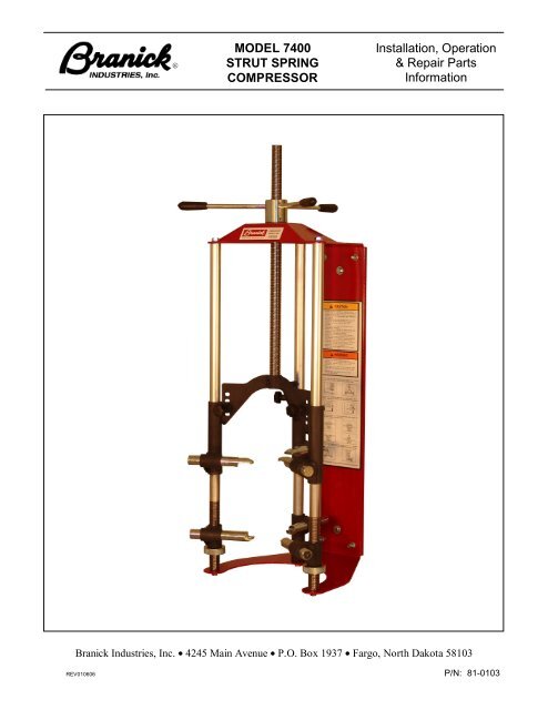
MODEL 7400STRUT SPRINGCOMPRESSORInstallation, Operation& Repair PartsInformation<strong>Branick</strong> <strong>Industries</strong>, Inc. • 4245 Main Avenue • P.O. Box 1937 • Fargo, North Dakota 58103REV010606 P/N: 81-0103
TABLE OF CONTENTS _______________________________________________________SAFETY INSTRUCTIONS 1DEFINITIONS 1SPECIFICATIONS 2INSTALLATION INSTRUCTIONS 2OPERATING INSTRUCTIONS 3Positioning the Strut Assembly 3Disassembly 6Reassembly 7MAINTENANCE 7REPAIR PARTS 8WARRANTY 10SAFETY INSTRUCTIONS _____________________________________________________• NEVER allow unauthorized personnel to operate this product.• NEVER use this product for anything other than its intended use.• THOROUGHLY train new employees in the proper use and care of this product.• PROHIBIT unauthorized personnel from being in shop area while this product is in use.DEFINITIONS _______________________________________________________________• CAUTION: Indicates a potentially hazardous situation, which if not avoided, may result in damage toproperty or minor personal injury.• HAZARD: A source of potential injury to a person.• MAINTENANCE: Those actions that preserve the correct and proper conditions under which themachine shall be used. This may include adjustment, replacement of wear items, lubrication andcleaning, but not modifications or repair of damage.• MAY: This word is understood to be permissive.• MUST: This word is understood to be mandatory.• OPERATION: The correct and proper use of the machine as described in this <strong>manual</strong>.• SAFETY ALERT SYMBOL: A symbol that indicates a potential personal safety hazard. It is composedof an equilateral triangle surrounding an exclamation point.• SHALL: This word is understood to be mandatory.• SHOULD: This word is understood to be advisory.• WARNING: Indicates a potentially hazardous situation, which if not avoided, may result in death orserious personal injury.1
CAUTION♦ Before using this product, read and fully understand the operatinginstructions and all decals on the product. This is necessary toprevent injury to the operator and damage to the product.♦ Do not attempt to use this product for anything other than itsintended purpose.♦ Do not use this product if it is visibly worn, distorted or damaged.♦ Always check condition of rubber hook pads on all six hooks beforeusing this tool. Replace if damaged or missing.♦ Always wear appropriate eye protection.♦ Inspect the spring of the strut assembly for any damage orcorrosion. Spring breakage during compression could cause injury.WARNING♦ Failure to properly position the strut assembly in tool could result inserious injury from sudden release of the strut assembly parts.SPECIFICATIONS ___________________________________________________________Max. Spring Compression Capacity ∙∙∙∙∙∙∙∙∙∙∙∙∙∙∙∙∙∙∙∙∙∙∙∙∙∙∙∙∙∙∙∙∙∙∙∙∙∙∙∙∙∙∙∙∙Min./Max. Spring Diameters ∙∙∙∙∙∙∙∙∙∙∙∙∙∙∙∙∙∙∙∙∙∙∙∙∙∙∙∙∙∙∙∙∙∙∙∙∙∙∙∙∙∙∙∙∙Packaged Dimensional data ∙∙∙∙∙∙∙∙∙∙∙∙∙∙∙∙∙∙∙∙∙∙∙∙∙∙∙∙∙∙∙∙∙∙∙∙∙∙∙∙∙∙∙∙∙111 cm)Shipping Weight ∙∙∙∙∙∙∙∙∙∙∙∙∙∙∙∙∙∙∙∙∙∙∙∙∙∙∙∙∙∙∙∙∙∙∙∙∙∙∙∙∙∙∙∙∙3000 lbs (1361 kgs)3.5 / 11.5 in (9 / 29 cm)18.5 x 20 x 43.63 in (47 x 51 x95 lbs (43 kgs)INSTALLATION INSTRUCTIONS________________________________________________1. Unpack and remove the unit from the shipping carton.2. Inspect the unit for any visible damage.3. Install on a solid vertical wall or post. (Can also be installed on an OPTIONAL benchmount and portablecart)4. Anchor the unit to the wall or post utilizing the two holes in the back plate. Make sure there is nomovement between the back plate and wall or post.2
OPERATING INSTRUCTIONS________________________________________________Step 1. Positioning the Strut AssemblyA) Adjust lower right hook to a position just below the lower center hook. Adjust lower left hook to a positionjust above the lower center hook.B) Place strut assembly on the lower center hook using the lowest possible coil of the spring.C) Engage lower left and right hooks with spring. Center the spring within lower hooks. The three lowerhooks should be equally extended.CORRECTINCORRECT3
D) Align strut assembly by adjusting the lower left and right hooks. When properly aligned, the spring of thestrut assembly will be parallel to the posts of the tool when viewed from both the front and side.FrontCORRECTFrontINCORRECTSideCORRECTSideINCORRECTE) Identify the strut assembly type you are servicing.Type 1 Type 2This type of strut has a bearing plate (which This type of strut has a bearing plate (whichrotates) and upper spring seat. Place upper rotates) and upper spring seat without spacehooks on the upper spring seat. Do not between them. Place upper hooks on theplace hooks on bearing plate.highest coil of the spring. Do not place hookson bearing plate.4
Type 3 Type 4This type of strut has only an upper spring This is a coil over shock. Place upper hooksseat. Place upper hooks on upper spring on the highest coil of the spring.seat.F) Engage all three upper hooks as shown above for the type of strut assembly you are servicing. Thethree upper hooks should be equally extended and contacting the strut.CORRECTINCORRECTCORRECTINCORRECT5
Step 2. DisassemblyCAUTION♦ If the strut assembly is difficult to compress or the spring bows ortilts, release tension and reposition the strut assembly.♦ Keep fingers and hands clear of the upper hook area at all times.A) With the strut assembly properly positioned, turn handles to compress spring until the bottom coil ofspring is just free of the lower spring seat. DO NOT OVER COMPRESS THE SPRING!B) Secure strut to spring with the clamp to prevent strut from dropping out unexpectedly.C) Mark upper strut parts to aid in reassembly.WARNING♦ Use extreme care when working with a compressed spring.♦ Never remove the piston rod nut when there is any spring pressureon the lower spring seat.D) Remove the piston rod nut.E) Remove the clamp while holding strut. Carefully remove strut and related parts.F) Service or replace strut as required. It is not necessary to release spring from tool when servicing strutonly.NOTE: When replacing top spring seat or spring, make note of the position of the spring seat and spring beforereleasing spring from tool. Replace new strut parts in tool in the same position as the old.6
Step 3. ReassemblyA) Position the new strut within spring. Secure strut to spring with the clamp.B) Install piston rod nut. NUT MUST BE FULLY ENGAGED ON PISTON ROD THREADS!C) Release pressure on spring. Remove the clamp. Remove strut assembly from tool.MAINTENANCE_____________________________________________________________NOTE: To avoid personal injury or damage to the Model 7400, permit only qualified personnel to performmaintenance.See repair parts breakdown for replacement parts.ALWAYS:DAILY:MONTHLY:PERIODICALLY:Keep hooks and pads free of oil and grease.Inspect thrust bearing, drive screw, hooks, posts, lock pins and slots forwear.Wipe down and clean ACME drive screw.Inspect unit for loose or missing components.YEARLY:Clean and lightly lubricate thrust bearing.___________________________________________________________________________OWNER’S RECORDSDate Installed: _______________________Date Code_______________________ Located under bottom plate___________________________________________________________________________7
REPAIR PARTS_____________________________________________________________8
MODEL 7400SERVICE PARTSITEM PART NO. QTY DESCRIPTION1 01-0085 2 POST2 01-0242 3 LOWER HOOK3 01-0243 3 UPPER HOOK4 028-064 4 CARRIAGE BOLT, 3/8-16 X 15 03-0418 1 BACK POST6 03-0420 1 UPPER REAR HOOK HOUSING7 03-0423 2 ADJUSTABLE HOOK HOUSING8 03-0425 1 UPPER RIGHT HOOK HOUSING9 03-0426 1 UPPER LEFT HOOK HOUSING10 03-0427 1 HOOK HOUSING11 055-103 1 NUT, 3/8-16 SERRATED HEX FLANGE12 055-154 4 NUT, 3/8-16 NYLON HEX LOCK13 055-160 1 NUT, 1/4-20 NYLON HEX LOCK14 06-0029 1 TOP PLATE15 06-0030 1 COMPRESSION HEAD16 06-0031 1 BOTTOM PLATE17 06-0032 1 BACK PANEL18 061-042 6 SPRING PIN, 3/16 X 3/819 061-091 3 SPRING PIN, 1/4 X 7/820 10-0011 3 HOOK PAD21 10-0012 3 HOOK PAD22 10-0022 3 HANDLE GRIP23 108-015 4 WASHER, 3/8 SAE FLAT24 108-137 1 WASHER, THRUST25 11-0075 3 ADJUSTER KNOB26 110-065 3 SPRING27 20-0043 1 BEARING, THRUST BALL28 20-0044 6 BEARING, NYLINER29 21-0006 1 HANDLE HUB30 21-0013 1 ACME DRIVE SCREW31 21-0014 1 THREADED HUB32 50-0025 1 SCREW, 5/16 X 1 SHOULDER33 50-0065 1 SCREW, 3/8-16 x 3/4 SERRATED FLANGE34 50-0068 6 SCREW, 1/2-13 X 1-1/4 SERRATED FLANGE35 51-0015 2 ACME ADJUSTMENT NUT36 53-0008 1 SPRING CLAMP37 54-0010 2 SPRING PIN, 3/16 X 9/1638 73-1000 3 LOCK PIN39 73-1005 3 THREADED HANDLE ROD40 80-0222 1 DECAL, INSTRUCTION41 80-0224 1 DECAL, MODLE 7400* 81-0103 1 INSTRUCTIONS, MODEL 7400 OPERATING* Item not shown9
________________________________________________________________<strong>Branick</strong> <strong>Industries</strong>, Inc.COMMERCIAL WARRANTYThis product is warranted by BRANICK INDUSTRIES, INC. to the original user-owner against defectivematerials or workmanship. During the warranty period, if <strong>Branick</strong> determines the product to bedefective, it will be repaired or replaced (at <strong>Branick</strong>’s option) without charge.Warranty Period1 year from date of delivery.This warranty does not cover defects in the product caused by ordinary wear and tear, abuse, misuse, overloading, accident (including shippingdamage), improper maintenance, alteration, or any other cause not the result of defective materials or workmanship.REPLACEMENT IS THE EXCLUSIVE REMEDY FOR DEFECTIVE PRODUCT UNDER THIS WARRANTY. THIS WARRANTY ISEXPRESSLY IN LIEU OF ALL OTHER WARRANTIES, INCLUDING ANY IMPLIED WARRANTY OF MERCHANTABILITY OR ANY IMPLIEDWARRANTY OF FITNESS FOR A PARTICULAR PURPOSE OF THIS PRODUCT. BRANICK INDUSTRIES, INC. SHALL NOT BE LIABLEFOR ANY CONSEQUENTIAL OR INCIDENTAL DAMAGES.BRANICK INDUSTRIES, INC. reserves the right to make changes in the design or construction of our products without obligation to incorporatesuch changes in products already sold and without notice.Service parts, warranty, and regular repair service are available from:BRANICK INDUSTRIES, INC.4245 Main Ave.Box 1937Fargo, North Dakota 58107701/281-8888________________________________________________________________© Copyright 2010 by <strong>Branick</strong> <strong>Industries</strong>, Inc. Printed in U.S.A.10