MAX II Development Kit Getting Started User Guide
MAX II Development Kit Getting Started User Guide
MAX II Development Kit Getting Started User Guide
You also want an ePaper? Increase the reach of your titles
YUMPU automatically turns print PDFs into web optimized ePapers that Google loves.
Reference Designs<br />
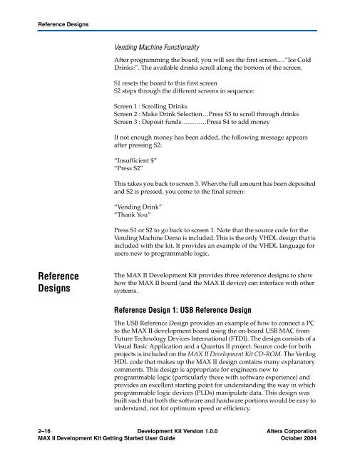
Vending Machine Functionality<br />
After programming the board, you will see the first screen….”Ice Cold<br />
Drinks:”. The available drinks scroll along the bottom of the screen.<br />
S1 resets the board to this first screen<br />
S2 steps through the different screens in sequence:<br />
Screen 1 : Scrolling Drinks<br />
Screen 2 : Make Drink Selection…Press S3 to scroll through drinks<br />
Screen 3 : Deposit funds…………Press S4 to add money<br />
If not enough money has been added, the following message appears<br />
after pressing S2:<br />
“Insufficient $”<br />
“Press S2”<br />
This takes you back to screen 3. When the full amount has been deposited<br />
and S2 is pressed, you come to the final screen:<br />
“Vending Drink”<br />
“Thank You”<br />
Press S1 or S2 to go back to screen 1. Note that the source code for the<br />
Vending Machine Demo is included. This is the only VHDL design that is<br />
included with the kit. It provides an example of the VHDL language for<br />
users new to programmable logic.<br />
Reference<br />
Designs<br />
The <strong>MAX</strong> <strong>II</strong> <strong>Development</strong> <strong>Kit</strong> provides three reference designs to show<br />
how the <strong>MAX</strong> <strong>II</strong> board (and the <strong>MAX</strong> <strong>II</strong> device) can interface with other<br />
systems.<br />
Reference Design 1: USB Reference Design<br />
The USB Reference Design provides an example of how to connect a PC<br />
to the <strong>MAX</strong> <strong>II</strong> development board using the on-board USB MAC from<br />
Future Technology Devices International (FTDI). The design consists of a<br />
Visual Basic Application and a Quartus <strong>II</strong> project. Source code for both<br />
projects is included on the <strong>MAX</strong> <strong>II</strong> <strong>Development</strong> <strong>Kit</strong> CD-ROM. The Verilog<br />
HDL code that makes up the <strong>MAX</strong> <strong>II</strong> design contains many explanatory<br />
comments. This design is appropriate for engineers new to<br />
programmable logic (particularly those with software experience) and<br />
provides an excellent starting point for understanding the way in which<br />
programmable logic devices (PLDs) manipulate data. This design was<br />
built such that both the software and hardware portions would be easy to<br />
understand, not for optimum speed or efficiency.<br />
2–16 <strong>Development</strong> <strong>Kit</strong> Version 1.0.0 Altera Corporation<br />
<strong>MAX</strong> <strong>II</strong> <strong>Development</strong> <strong>Kit</strong> <strong>Getting</strong> <strong>Started</strong> <strong>User</strong> <strong>Guide</strong> October 2004


