![Download [PDF] - InventorCAM](https://img.yumpu.com/39563310/37/500x640/download-pdf-inventorcam.jpg)
Download [PDF] - InventorCAM
Download [PDF] - InventorCAM
Download [PDF] - InventorCAM

You also want an ePaper? Increase the reach of your titles
YUMPU automatically turns print PDFs into web optimized ePapers that Google loves.
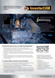
MILL-TURN<br />
The mill_turn1_IV.prz example illustrates the use of the <strong>InventorCAM</strong> Mill-<br />
Turn module for the machining of the optical part shown above, on a 4-axis<br />
Mill-Turn CNC-Machine.<br />
The following Turning and Milling operations are used to perform the<br />
machining of the part:<br />
• Turning<br />
(TR_profile_1; DRILL_; TR_profile_10)<br />
These turning operations are used to generate the tool path<br />
for the rough and finish machining of the external and internal<br />
cylindrical faces.<br />
• Facial Milling (F_profile_2; D_drill_3; D_drill_4)<br />
These operations perform the machining of the screw slot and<br />
four holes using <strong>InventorCAM</strong> capabilities for facial milling.<br />
Position #1 of Coordinate System #1 is used to perform the facial<br />
machining.<br />
• Machining of the side faces (P_profile_3)<br />
This Pocket operation is used to perform the machining of the side<br />
faces of the model. The Contour strategy is used in combination<br />
with a negative Wall offset value in order to generate an<br />
overlapping tool path that completely machines the faces.<br />
38<br />
CoordSys Position #3 is used for the operation. The Transform option is<br />
used to create a circular pattern of operations around the revolution axis.<br />
<strong>InventorCAM</strong> + Inventor = The Complete Integrated Manufacturing Solution

![Manual [PDF] - InventorCAM](https://img.yumpu.com/49966902/1/190x245/manual-pdf-inventorcam.jpg?quality=85)

![Manual [PDF] - InventorCAM](https://img.yumpu.com/48886276/1/190x245/manual-pdf-inventorcam.jpg?quality=85)

![Download [PDF] - InventorCAM CAM Software](https://img.yumpu.com/39560718/1/184x260/download-pdf-inventorcam-cam-software.jpg?quality=85)