Operating Instructions and Service Manual Xdc-96Pro ... - FluidX
Operating Instructions and Service Manual Xdc-96Pro ... - FluidX
Operating Instructions and Service Manual Xdc-96Pro ... - FluidX

You also want an ePaper? Increase the reach of your titles
YUMPU automatically turns print PDFs into web optimized ePapers that Google loves.
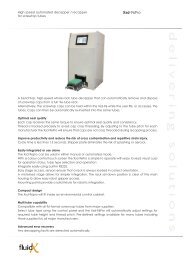
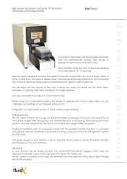
<strong>Operating</strong> <strong>Instructions</strong> <strong>and</strong><br />
<strong>Service</strong> <strong>Manual</strong><br />
<strong>Xdc</strong>-<strong>96Pro</strong> Decapper-Recapper<br />
__________________________________<br />
April 2008 v3<br />
<strong>FluidX</strong> Ltd. Monks Heath Hall, Chelford Road, Nether Alderley, Cheshire, SK10 4SY, UK.<br />
T: +44(0) 1625 861 614 F: +44(0) 1625 861 615 E: info@fluidx.co.uk www.fluidx.co.uk<br />
- 1 -
This document is for information only; the manufacturer accepts no liability for errors<br />
contained herein or for incidental or consequential damages with the furnishing,<br />
performance, or use of this material.<br />
Unless otherwise specified references to names or parts is purely casual <strong>and</strong> has the<br />
purpose of illustrating the product. The contents of this publication may not be reproduced in<br />
any form or by any means (including electronic storage <strong>and</strong> retrieval or translation into a<br />
foreign language) without prior agreement <strong>and</strong> written consent from the copyright owner.<br />
The information contained in this document is subject to change without notice.<br />
- 2 -
CONTENTS<br />
1. WARNINGS 5<br />
1.1. SYMBOLS<br />
2. APPLICABLE RULES 6<br />
3. GENERAL SPECIFICATIONS 6<br />
4. TECHNICAL SPECIFICATIONS 7<br />
5. EQUIPMENT DESCRIPTION 8<br />
5.1. LOADING ZONE<br />
5.2. CAP UNLOADING ZONE<br />
5.3. COMMAND PANEL<br />
5.4. CONNECTION PANEL<br />
6. CONFIGURING THE XDC-96PRO FOR USE WITH SPECIFIC RACK TYPES 11<br />
6.1. CONFIGURATION FOR MATRIX TECHNOLOGIES RACKED TUBES<br />
6.2. CONFIGURATION FOR FLUIDX AND MICRONIC RACKED TUBES<br />
6.3. CONFIGURATION FOR ABGENE RACKED TUBES<br />
7. UNPACKING AND PRELIMINARY OPERATION 17<br />
7.1. INSTALLATION<br />
7.2. VOLTAGE SELECTION<br />
7.3. ELECTRICAL CONNECTIONS<br />
7.4. PNEUMATIC CONNECTION<br />
7.5. USE WITH MATRIX TECHNOLOGIES RACK TYPES<br />
7.6. USE WITH FLUIDX AND MICRONIC RACK TYPES<br />
7.7. USE WITH ABGENE RACK YPES<br />
8. CONFIGURING THE XDC-96PRO FOR USE WITH HIGH, MEDIUM<br />
OR LOW PROFILE RACKS 21<br />
8.1. CHANGING CONFIGURATION FOR MEDIUM OR LOW PROFILE RACK USE<br />
9. RACK PLACEMENT 23<br />
10. BASIC FUNCTIONS 24<br />
10.1. PERFORMING DECAPPING WITH CAP DISPOSAL/WASTE<br />
10.2. PERFORMING DECAPPING WITHOUT CAP DISPOSAL/WASTE<br />
10.3. RECAPPING TUBES<br />
10.4. DISPOSAL OF CAPS AFTER DECAPPING<br />
10.5. PERFORMING A PURGE<br />
10.6. ERROR INDICATION<br />
10.7. LED STATUS SPECIFICATIONS<br />
11. DECAPPING A SINGLE ROW 29<br />
11.1. SELECTING ROW TO BE DECAPPED<br />
11.2. DECAPPING A SINGLE ROW WITH CAP DISPOSAL<br />
11.3. DECAPPING A SINGLE ROW WITHOUT CAP DISPOSAL<br />
11.4. RECAPPING A SINGLE ROW<br />
11.5. DECAPPING A SINGLE ROW WITH CAP DISPOSAL<br />
- 3 -
11.6. SINGLE ROW PURGE<br />
12. SINGLE ROW TOOTH MODEL SELECTION 32<br />
13. DECLARATION OF EU COMPLIANCE 34<br />
14. INSTRUMENT MAINTENANCE 35<br />
15. GENERAL TROUBLESHOOTING TIPS 36<br />
16. SWITCHING BETWEEN 115 AND 230V 36<br />
17. HEDGEHOG COMMUNICATION FAILURE 37<br />
18. CALIBRATION 38<br />
18.1. INTRODUCTION<br />
18.2. MOTOR LIMITS<br />
18.3. ALIGNMENT<br />
18.4. ADJUSTING ALIGNMENT<br />
18.5. SLEDGE MOTOR POSITIONING<br />
19. REGULAR MAINTENANCE/SERVICE 44<br />
19.1. COVER REMOVAL<br />
19.2. GENERAL INSPECTION<br />
19.3. SLEDGE INSPECTION<br />
19.4. HARPOON INSPECTION<br />
19.5. COVER MOUNTING<br />
19.6. KEYBOARD AND SENSOR TEST<br />
19.7. DECAPPING TEST<br />
19.8. RECAPPING TEST<br />
19.9. CAP DISPOSAL TEST<br />
19.10. OPTIONAL TESTS, GAS LINE<br />
20. SPARE PARTS 47<br />
20.1. BOARDS AND CABLES<br />
20.2. SPARE PARTS, GAS OPTION<br />
20.3. SPARE PARTS, MISCELLANEOUS<br />
20.4. SPARE PARTS, MOTORS<br />
20.5. SPARE PARTS, STANDARD UNIT<br />
21. SERIAL PROTOCOL 54<br />
- 4 -
1. WARNINGS<br />
Please read the following before unpacking or using the unit.<br />
i. Check voltage before switching ON the <strong>Xdc</strong>-96pro.<br />
ii.<br />
iii.<br />
iv.<br />
Only use fuses of the type <strong>and</strong> current rating specified. Do not use repaired fuses. Do<br />
not short-circuit the fuse holder.<br />
The supplied power cord must be inserted into a power outlet with a protective earth<br />
contact (ground). When using an extension cord, ensure the cord also has an earth<br />
contact.<br />
Do not change the external or internal grounding connections. Tampering with, or<br />
disconnecting these connections could endanger you <strong>and</strong>/or damage the <strong>Xdc</strong>-96pro.<br />
The <strong>Xdc</strong>-96pro is properly grounded in accordance with these regulations when<br />
shipped.<br />
v. Changes to the electrical connections or to the chassis of the <strong>Xdc</strong>-96pro are not<br />
required to ensure safe operation.<br />
vi.<br />
vii.<br />
viii.<br />
ix.<br />
Do not turn the <strong>Xdc</strong>-96pro on if you suspect that it has incurred any kind of electrical<br />
damage. Instead disconnect the power cord <strong>and</strong> contact a <strong>FluidX</strong> representative for a<br />
product evaluation. Do not attempt to use the <strong>Xdc</strong>-96pro until it has been evaluated.<br />
Electrical damage may have occurred if the <strong>Xdc</strong>-96pro shows visible signs of<br />
damage, or has been transported under severe stress.<br />
Damage can also result if the <strong>Xdc</strong>-96pro has been stored for prolonged periods under<br />
unfavourable conditions (e.g. subjected to heat, water, etc.).<br />
Always disconnect the power cord before attempting any type of maintenance.<br />
Capacitors inside the <strong>Xdc</strong>-96pro may still be charged even if the <strong>Xdc</strong>-96pro is turned<br />
off.<br />
The <strong>Xdc</strong>-96pro includes a number of integrated circuits. These circuits may be<br />
damaged if exposed to excessive line voltage fluctuations <strong>and</strong>/or power surges.<br />
x. Never try to repair or replace any components of the <strong>Xdc</strong>-96pro not described in this<br />
manual without the assistance of a <strong>FluidX</strong> representative.<br />
1.1 SYMBOLS<br />
The following symbols are used within this manual:<br />
Do not touch<br />
Warning, check the manual<br />
High Voltage<br />
- 5 -
2. APPLICABLE RULES<br />
73/23/CEE Low Voltage Rule<br />
89/336/CEE Electromagnetic Compatibility Rule<br />
93/68 Rules modification 73/23 e 89/336 CEE<br />
3. GENERAL SPECIFICATIONS<br />
i. The <strong>Xdc</strong>-96pro is a decapper/recapper, designed for use with racked tubes supplied<br />
by <strong>FluidX</strong>®, Matrix Technologies®, Micronic® <strong>and</strong> Abgene®.<br />
ii.<br />
iii.<br />
iv.<br />
The decapper/recapper will have been configured for use with a specific rack model<br />
by a qualified technician.<br />
The <strong>Xdc</strong>-96pro can decap <strong>and</strong> then either dispose of the caps or recap the tubes. A<br />
purge option allows the <strong>Xdc</strong>-96pro to decap <strong>and</strong>/or recap in an inert atmosphere.<br />
The instrument can be controlled using a PC, connected via the RS 232 interface, or<br />
by using a control panel found at the front of the unit.<br />
- 6 -
4. TECHNICAL SPECIFICATIONS<br />
DIMENSIONS<br />
Control Module<br />
Height<br />
Width<br />
Depth<br />
Power Cable<br />
Length<br />
350mm<br />
215mm<br />
680mm<br />
WEIGHT Control Module 15kg<br />
ENVIROMENTAL<br />
POWER SUPPLY<br />
PURGE VALVE<br />
Operative Temperature<br />
Relative Humidity ( not<br />
condensing )<br />
Line Voltage<br />
Frequency<br />
Power<br />
Pressure Limit<br />
Pneumatic Interface<br />
2m<br />
15 - 35 °C<br />
5 - 85 % Max.<br />
115 - 230 +/-10% Vac<br />
50/60 Hz<br />
160 VA<br />
1 BAR (15 PSI or 100<br />
Kpa)<br />
Rapid connector tube Ø 4<br />
mm<br />
- 7 -
5. EQUIPMENT DESCRIPTION<br />
<strong>Xdc</strong>-96pro consists of the following components:<br />
• Loading zone<br />
• Cap unloading zone<br />
• Comm<strong>and</strong> panel<br />
• Connection panel<br />
• Mechanical interface<br />
5.1 LOADING ZONE<br />
1<br />
2<br />
3<br />
7<br />
3<br />
4<br />
8<br />
6<br />
4<br />
5<br />
FIG 2.1 FIG 2.2<br />
i. The loading zone is composed of:<br />
• Eight spray nozzles (Fig 2.1 - 1)<br />
• Caps disposal chute (Fig 2.1 - 2)<br />
• Mechanical holder (Fig 2.1 - 3 or Figure 2.2 - 3)<br />
• Locking tooth (Fig 2.1 - 4 / 2.2 - 5, details on Fig 2.8 to 2.10)<br />
• Locking screw (Fig 2.2 - 5)<br />
• Locking tooth screw (Fig 2.1 - 6)<br />
• Rack alignment cones (Fig 2.1 - 7)<br />
ii. Rack sliding movement (Fig 2.1 - 8)<br />
a. The loading zone is defined by six alignment cones. The mechanical<br />
configuration (e.g. adapter, teeth) for the rack type to be used will be<br />
positioned in advance.<br />
b. The rack to be decapped/recapped is inserted between the six alignment<br />
cones.<br />
c. At the beginning of the run, the rack will slide inside the unit from the loading<br />
position <strong>and</strong> into the decap/recap area. The rack is then locked into position.<br />
- 8 -
d. At the end of the run the rack is returned to the loading position <strong>and</strong> the lock is<br />
automatically released.<br />
e. A series of spray nozzles can be used to add inert gas into the decap area<br />
<strong>and</strong> tubes. This can be performed after decapping or prior to recapping.<br />
5.2 CAP UNLOADING ZONE<br />
i. The outlet for the removed caps (for disposal rather than recapping) is found on the<br />
right side of the <strong>Xdc</strong>-96pro.<br />
UNLOADING<br />
ZONE<br />
FIG 2.2A<br />
ii.<br />
During the decap (with cap disposal) procedure, or cap disposal only procedure, the<br />
caps are removed from the unit via a waste chute which leads to the unloading hole<br />
(see Fig 2.2A).<br />
WARNING<br />
To prevent caps scattering place a collecting box under cap unloading zone.<br />
- 9 -
5.3 COMMAND PANEL<br />
1<br />
2<br />
3<br />
4<br />
5<br />
6<br />
7<br />
8<br />
9<br />
FIG 2.3<br />
i. The comm<strong>and</strong> panel consists of five LEDs, which indicate the unit status, <strong>and</strong> four<br />
keys, used to manage the decap/recap/cap disposal procedures or commence a<br />
purge procedure.<br />
ii.<br />
The comm<strong>and</strong> panel is made up of:<br />
• READY LED (Fig 2.3 -1)<br />
• RUN LED (Fig 2.3 -2)<br />
• RECAP LED (Fig 2.3 -3)<br />
• WASTE /disposal LED (Fig 2.3 -4)<br />
• ERROR LED (Fig 2.3 -5)<br />
• STOP Key (Fig 2.3 -6)<br />
• START Key (Fig 2.3 -7)<br />
• RECAP Key (Fig 2.3 -8)<br />
• WASTE Key (Fig 2.3 -9)<br />
5.4 CONNECTION PANEL<br />
i. The connection panel is composed of:<br />
• Inert gas inlet (see Fig 2.4 - 1)<br />
• Fuse <strong>and</strong> Voltage selector box<br />
(see Fig 2.4 – 2)<br />
• Power switch ON/OFF<br />
(see Fig 2.4 – 3)<br />
• Power connector (see Fig 2.4 – 4)<br />
• RS 232 serial port (see Fig 2.4 - 5)<br />
• I/O Remote control interface<br />
(see Fig 2.4 – 6).<br />
2<br />
3<br />
4<br />
1<br />
5<br />
6<br />
FIG 2.4<br />
- 10 -
6. CONFIGURING THE XDC-96PRO FOR USE WITH SPECIFIC RACK TYPES.<br />
i. The <strong>Xdc</strong>-96pro is compatible with racked tubes supplied by <strong>FluidX</strong>, Matrix Technologies,<br />
Abgene <strong>and</strong> Micronic, when used with the appropriate mechanical configuration,<br />
including:<br />
• High, medium <strong>and</strong> low profile racked tubes from Matrix Technologies <strong>and</strong> Abgene.<br />
• High <strong>and</strong> medium profile racked tubes from Micronic <strong>and</strong> <strong>FluidX</strong>.<br />
ii. Each rack-specific configuration is composed of:<br />
• Mechanical adapter<br />
• Spacer for mechanical adapter<br />
• Locking tooth<br />
• Spacer for locking tooth<br />
6.1 CONFIGURATION FOR MATRIX TECHNOLOGIES RACKED TUBES.<br />
FIG 2.5 FIG 2.6<br />
1<br />
2<br />
FIG 2.7<br />
FIG 2.8 FIG 2.9<br />
FIG 2.10 FIG 2.11<br />
- 11 -
iii.<br />
The mechanical configuration for use with Matrix racks consists of:<br />
• Mechanical holder (see Fig 2.4/2.5)<br />
• Mechanical adapter, medium profile rack configuration (see Fig 2.6 – 2)<br />
• Mechanical adapter, low profile rack configuration (see Fig 2.6 – 1)<br />
• Locking tooth spacer, medium profile rack configuration (see Fig 2.7)<br />
• Locking tooth spacer, low profile rack configuration (see Fig 2.8)<br />
• Locking tooth for use with Matrix racks (see Fig 2.10-2.11).<br />
iv.<br />
Matrix Technologies rack specifications<br />
TABLE 1<br />
RACK PROFILE<br />
TYPE (HEIGHT)<br />
HOLDER<br />
HEIGHT<br />
(SCREW)<br />
ADAPTER<br />
HEIGHT<br />
LOCKING TOOTH<br />
HEIGHT (SCREW)<br />
LOCKING<br />
TOOTH SPACER<br />
HIGH (29,40)<br />
1.4 ml sepra seal<br />
5.9<br />
(TCC M4x06)<br />
-- 12<br />
(TCEI M3X12)<br />
--<br />
MEDIUM (29,40)<br />
0.7 ml sepra seal<br />
5.9<br />
(TCC M4x16)<br />
10.4<br />
12<br />
(TCEI M3X22)<br />
10.4<br />
LOW (14,60)<br />
0.4 ml sepra seal<br />
5.9<br />
(TCC M4x30)<br />
23.1<br />
12<br />
(TCEI M3X35)<br />
19.7<br />
Heights are in mm - Screws are in metric units<br />
TCC : Cross-tip screw with cylindrical head<br />
TCEI : Allen screw with cylindrical head<br />
- 12 -
6.2 CONFIGURATION FOR FLUIDX AND MICRONIC RACKED TUBES.<br />
FIG 2.12 FIG 2.13<br />
FIG 2.14 FIG 2.15<br />
FIG 2.16 FIG 2.17<br />
FIG 2.18<br />
Mechanical configuration for use with <strong>FluidX</strong> <strong>and</strong> Micronic racks consists of:<br />
• Mechanical holder for <strong>FluidX</strong> <strong>and</strong> Micronic racks (see Fig 2.12/2.13)<br />
• Mechanical adapter, medium profile rack configuration (see Fig 2.14/2.15)<br />
• Locking tooth spacer, medium profile rack configuration (see Fig 2.16)<br />
• Locking tooth for use with <strong>FluidX</strong> <strong>and</strong> Micronic racks (see Fig 2.17/2.18).<br />
- 13 -
v. <strong>FluidX</strong> <strong>and</strong> Micronic rack specifications.<br />
TABLE 2<br />
RACK PROFILE<br />
TYPE<br />
(HEIGHT)<br />
HOLDER<br />
HEIGHT<br />
(SCREW)<br />
ADAPTER<br />
HEIGHT<br />
LOCKING TOOTH<br />
HEIGHT<br />
(SCREW)<br />
LOCKING<br />
TOOTH SPACER<br />
HIGH (28.30)<br />
1.4 ml<br />
6.5<br />
(TCC M4x07)<br />
-- 14.9<br />
(TCEI M3X16)<br />
--<br />
MEDIUM (11)<br />
0.65 ml<br />
6.5<br />
(TCC M4x25)<br />
18.1<br />
17.9<br />
(TCEI M3X25)<br />
8.9<br />
Heights are in mm - Screws are in metric units<br />
TCC: Cross-tip screw with cylindrical head<br />
TCEI: Allen screw with cylindrical head<br />
- 14 -
6.3 CONFIGURATION FORABGENE RACKED TUBES.<br />
FIG 2.19 FIG 2.20<br />
1 2<br />
FIG 2.21<br />
FIG 2.22 FIG 2.23<br />
FIG 2.24 FIG 2.25<br />
vi.<br />
Mechanical configuration for use with Abgene racks consists of:<br />
• Mechanical adapter (see Fig 2.17/2.18)<br />
• Spacer for mechanical adapter, medium profile rack configuration (see item 1 of Fig<br />
2.19)<br />
• Spacer for mechanical adapter, low profile rack configuration (see item 2 of Fig 2.19)<br />
• Spacer for locking tooth, medium profile rack configuration (see Fig 2.20)<br />
• Spacer for locking tooth, low profile rack configuration (see Fig 2.21)<br />
• Locking tooth for use with Abgene racks (see Fig 2.24-2.25)<br />
Note. The same locking tooth is used for racks provided by Abgene <strong>and</strong> Matrix<br />
Technologies<br />
- 15 -
vii.<br />
Abgene rack specifications<br />
TABLE 3<br />
RACK PROFILE<br />
TYPE<br />
HOLDER<br />
HEIGHT<br />
(SCREW)<br />
ADAPTER<br />
HEIGHT<br />
LOCKING TOOTH<br />
HEIGHT<br />
(SCREW)<br />
LOCKING<br />
TOOTH SPACER<br />
HIGH (31.70)<br />
1.4 ml<br />
4.0<br />
(TSC M4x08)<br />
-- 12<br />
(TCEI M3X12)<br />
--<br />
MEDIUM (16.60)<br />
0.75 ml<br />
4.0<br />
(TSC M4x25)<br />
17.3<br />
12<br />
(TCEI M3X25)<br />
11.5<br />
LOW (16.60)<br />
0.5 ml<br />
5.9<br />
(TSC M4x35)<br />
26.7<br />
12<br />
(TCEI M3X35)<br />
20.9<br />
Heights are in mm - Screws are in metric units<br />
TSC : Cross-tip screw with cone-shaped head<br />
TCEI: Allen screw with cylindrical head<br />
- 16 -
7. UNPACKING AND PRELIMINARY OPERATION<br />
Use care when unpacking the unit.<br />
i. First check the integrity of the box to establish whether external damage occurred in<br />
transit. If damage is seen please inform your supplierr <strong>and</strong> keep the box as evidence.<br />
ii.<br />
When the <strong>Xdc</strong>-96pro has been unpacked, check the integrity of the instrument <strong>and</strong> ensure<br />
that all the accessories are provided (compare with delivery note enclosed). Please advise<br />
your supplier of any discrepancies.<br />
7.1 INSTALLATION<br />
i. After unpacking, position the system on a benchtop <strong>and</strong> ensure that the correct voltage is<br />
selected (see Voltage Selection section) <strong>and</strong> connect cables (see Electrical Connections<br />
section).<br />
ii.<br />
The <strong>Xdc</strong>-96pro is supplied with the mechanical adapter <strong>and</strong> locking tooth required for use<br />
with high profile racks in position. The user must install the following items if medium or<br />
low profile racks are to be used:<br />
• The mechanical adapter is secured beneath the holder, using the screw<br />
supplied (see table 1-3 )<br />
• The locking tooth spacer is also secured with a supplied screw (see table 1-3).<br />
iii.<br />
Install the adapter <strong>and</strong> locking tooth while system is switched off, then place rack on the<br />
loading point <strong>and</strong> switch on.<br />
7.2 VOLTAGE SELECTION<br />
i. Ensure that the <strong>Xdc</strong>-96pro is not connected to the main power.<br />
ii.<br />
iii.<br />
iv.<br />
A connection panel is situated on the reverse of the <strong>Xdc</strong>-96pro (see Fig 2.3). The voltage<br />
required is written in white.<br />
The decapper is normally set on 230V but can be easily changed to use either 110 or<br />
230V.<br />
To change voltage:<br />
• Switch off the equipment.<br />
• Unplug the power cable.<br />
• Open fuse box with a screwdriver.<br />
• With the same screwdriver, extract the fuse compartment.<br />
• Replace the two fuses with fuses of the required amperage. See table over.<br />
- 17 -
TABLE 4<br />
Power voltage Fuse Type ( EN 60127<br />
115 V 0,8 A T<br />
230 V 0,5 A T<br />
• Insert the fuse with the correct voltage at the top.<br />
• Close the fuse box by pressing gently.<br />
• The selected voltage can be read if the fuse compartment is correctly<br />
inserted.<br />
• Plug in the power cable.<br />
7.3 ELECTRICAL CONNECTIONS<br />
i. Follow these instructions when connecting.<br />
Warning<br />
Check that the unit is switched OFF<br />
ii.<br />
iii.<br />
iv.<br />
Plug power cable in to the <strong>Xdc</strong>-96pro <strong>and</strong> then insert nto the main power supply.<br />
If serial mode is desired, use the cable supplied to connect the PC RS232 port to the<br />
unit.<br />
The 15 pin connection can be used to interface the instrument with a system to<br />
enable a rack to be loaded onto the adapter.<br />
7.4 PNEUMATIC CONNECTION<br />
i. Connect the gas inlet for the purge gas to a suiteable gas source. The gas line must be<br />
regulated. The inlet pressure must not exceed 1 Bar (15 PSI or 100 Kpa).<br />
WARNING<br />
When installing an external pressure regulator, ensure pressure overload is<br />
prevented.<br />
- 18 -
4.5 USE WITH MATRIX TECHNOLOGIES RACK TYPES<br />
i. The instrument is able to decap <strong>and</strong> recap caps from three types of storage tube<br />
racks supplied by Matrix Technologies.<br />
TABLE 5<br />
TYPE<br />
Rack height<br />
(mm)<br />
Tube size (ml) Cap Type<br />
HIGH 29.40 1.4 Matrix Sepra seal<br />
MEDIUM 29.40 0.7 Matrix Sepra seal<br />
LOW 14.60 0.4 Matrix Sepra seal<br />
FIG 3.1<br />
High profile<br />
FIG 3.2<br />
Medium profile<br />
FIG 3.3<br />
Low profile<br />
7.6 USE WITH FLUIDX AND MICRONIC RACK TYPES<br />
i. The instrument is able to decap <strong>and</strong> recap caps from two types of storage tube racks<br />
supplied by <strong>FluidX</strong> <strong>and</strong> Micronic.<br />
TABLE 6<br />
TYPE<br />
Rack height<br />
(mm)<br />
Tube size (ml) Cap Type<br />
HIGH 28.30 1.4 Capclusters<br />
MEDIUM 11 0.65/0.75 Capclusters<br />
FIG 3.4<br />
High profile<br />
FIG 3.5<br />
Medium profile<br />
- 19 -
7.7 USE WITH ABGENE RACK TYPES<br />
i. The instrument is able to decap <strong>and</strong> recap caps three types of storage tube racks<br />
supplied by Abgene.<br />
TABLE 7<br />
TYPE<br />
Rack height<br />
(mm)<br />
Tube size (ml)<br />
HIGH 31.70 1.4<br />
MEDIUM 16.60 0.75<br />
LOW 16.60 0.5<br />
Cap Type<br />
FIG 3.6<br />
High profile<br />
FIG 3.7<br />
Medium profile<br />
FIG 3.8<br />
Low profile<br />
- 20 -
8. CONFIGURING THE XDC-96PRO FOR USE WITH HIGH, MEDIUM AND LOW<br />
PROFILE RACKS.<br />
i. Initailly the unit is usually set up for use with high profile racks.<br />
ii.<br />
To use the <strong>Xdc</strong>-96pro with medium or low profile racks (from the same manufacturer)<br />
only two steps are required:<br />
• Install the holder, <strong>and</strong> dedicated adapter, <strong>and</strong> screw into position.<br />
• Install associated locking tooth <strong>and</strong> spacers, <strong>and</strong> screw into place.<br />
(See Table 1.3).<br />
iii.<br />
Once these changes have been made the <strong>Xdc</strong>-96 pro is ready to use.<br />
8.1 CHANGING CONFIGURATION FOR MEDIUM OR LOW PROFILE RACK USE<br />
WARNING<br />
<strong>Xdc</strong>-96pro must be turned off before changing configuration.<br />
iv.<br />
To install the mechanical configuration for use with either medium or low profile racks:<br />
• Remove the locking tooth (Symbol X in Fig 3.9/3.10/3.11).<br />
• Insert the appropriate tooth spacer for medium/low configuration (Fig 3.12 <strong>and</strong><br />
Table 1.3).<br />
• Place the locking tooth on the spacer <strong>and</strong> fsecure with screw provided (Fig 3.13<br />
<strong>and</strong> Table 1.3).<br />
• Remove the holder screw from the adapter (Fig 3.14-1) <strong>and</strong> remove the<br />
mechanical holder (Figure 3.15).<br />
• Insert the spacer required for medium/low profile rack use (Fig 3.16/3.17).<br />
• Install the holder. Ensure that the holder is installed with the locking tooth housing<br />
placed on the same side as the locking tooth (Fig 3.18).<br />
• Lock holder in position with screw provided.<br />
- 21 -
X X<br />
X<br />
FIG 3.9 FIG 3.10 FIG 3.11<br />
LOCKING TOOTH HOUSING<br />
1<br />
FIG 3.12 FIG 3.13 FIG 3.14<br />
FIG 3.15 FIG 3.16 FIG 3.17<br />
FIG 3.18<br />
- 22 -
9. RACK PLACEMENT<br />
i. After completing configuration, place the racked tubes on the adapter without cover.<br />
ii.<br />
The following images show rack positions for high, medium <strong>and</strong> low profile racks:<br />
FIG 3.19<br />
High profile rack holder ,<br />
ready for use<br />
FIG 3.20<br />
High profile rack holder ,<br />
loading<br />
FIG 3.21<br />
High profile rack holder,<br />
lock & run<br />
FIG 3.22<br />
Medium profile rack holder,<br />
ready for use<br />
FIG 3.23<br />
Medium profile rack holder,<br />
loading<br />
FIG 3.24<br />
Medium profile rack holder ,<br />
lock & run<br />
FIG 3.25<br />
Low profile rack holder,<br />
ready for use<br />
FIG 3.26<br />
Low profile rack holder,<br />
loading<br />
FIG 3.27<br />
Low profile rack holder,<br />
lock & run<br />
- 23 -
10. BASIC FUNCTIONS<br />
i. The initialising process starts when the instrument is turned on, the “RUN” LED<br />
starts blinking. When completed, the <strong>Xdc</strong>-96pro is ready for use, the “RUN “LED is<br />
off <strong>and</strong> the “READY” <strong>and</strong> “RECAP” LEDs are on.<br />
FIG 4.1<br />
<strong>Xdc</strong>-96pro ready for use with recapping option selected.<br />
10.1 PERFORMING DECAPPING WITH CAP DISPOSAL<br />
i. After initalising, place rack on rack holder.<br />
ii.<br />
Press “RECAP” key <strong>and</strong> ensure RECAP LED is off.<br />
FIG 4.2 <strong>Xdc</strong>-96pro ready for use without recapping option chosen.<br />
iii.<br />
iv.<br />
While the procedure is in progress the “READY” LED is off, <strong>and</strong> the “RUN” LED will<br />
be lit.<br />
At the end of the procedure the rack will be decapped <strong>and</strong> the caps are disposed of<br />
through the window placed at right side of the instrument.<br />
10.2 PERFORMING DECAPPING WITHOUT CAP DISPOSAL<br />
i. After initializing, place rack on the rack holder.<br />
ii.<br />
Press the “RECAP” key.<br />
- 24 -
FIG 4.3<br />
<strong>Xdc</strong>-96pro ready for use with recapping option selected<br />
iii.<br />
iv.<br />
Press “START” key to commence decapping procedure.<br />
The rack is decapped <strong>and</strong> the caps retained on <strong>Xdc</strong>-96pro internal harpoons, ready<br />
for rack recapping in the future.<br />
v. The “RECAP” LED will blink to indicate that caps are retained on the internal<br />
harpoons.<br />
10.3 TO RECAPPING TUBES<br />
i. After decapping with recapping option selected the “RECAP” LED will blink <strong>and</strong> the<br />
caps retained on internal harpoons. It is then possible to recap the previously<br />
decapped racked tubes.<br />
ii.<br />
Press “START” key to commence recapping procedure.<br />
FIG 4.4<br />
<strong>Xdc</strong>-96pro ready to use with recapping option selected.<br />
iii.<br />
While procedure is in progress, the “RUN” LED will be lit <strong>and</strong> the “RECAP” LED will<br />
blink.<br />
10.4 DISPOSAL OF CAPS AFTER DECAPPING<br />
i. With <strong>Xdc</strong>-96 pro iready for use (see Fig 4.1/4.2/4.3) press WASTE key for 2<br />
seconds to start the cap disposal procedure.<br />
- 25 -
Fig 4.5<br />
Cap disposal procedure running<br />
10.5 PERFORMING A PURGE<br />
i. With <strong>Xdc</strong>-96 pro ready to use (see Fig 4.1/4.2/4.3/4.4) press “STOP” key for two<br />
seconds to commence purge procedure.<br />
ii.<br />
iii.<br />
iv.<br />
The procedure will only start if the initial purge time is greater than zero (set by<br />
serial interface).<br />
Purge Ev is activated for the initial purge time.<br />
During purge process the “RUN” <strong>and</strong> “WASTE” LEDs will blink.<br />
v. The purge procedure can be aborted by pressing the “STOP” key for two seconds.<br />
vi.<br />
The initial purge time will be set by a qualified technician, please contact supplier to<br />
modify.<br />
Fig 4.6 Purge process in progress<br />
WARNING Place <strong>Xdc</strong>-96pro under aspirating hood if gas used is<br />
considered dangerous. Use external regulator if gas pressure is too high.<br />
- 26 -
10.6 ERROR INDICATION<br />
i. The red “ERROR” LED will blink to indicate error detection.<br />
ii.<br />
To cancel press “STOP” key.<br />
10.7 LED STATUS SPECIFICATIONS<br />
i. Please note that these specifications remain under development.<br />
LED STATUS<br />
STATUS DESCRIPTION READY RUN RECAP WASTE ERROR<br />
BOOTING FIRST PHASE<br />
PROGRAM BOOT<br />
WAITING PC LINK<br />
OFF ON ON OFF OFF<br />
BOOTING SECOND PHASE PROGRAM BOOTING OFF OFF ON OFF OFF<br />
INITIALIZE<br />
SYSTEM<br />
INITIALIZATION<br />
OFF BLINK OFF OFF OFF<br />
READY TO RECAP READY TO RUN ON OFF OFF OFF OFF<br />
READY (OPTION RECAP SELECT) READY TO RUN ON OFF ON OFF OFF<br />
READY WAIT RECAPPING<br />
RUNNING (OPTION RECAP)<br />
RUNNING (NO OPTION RECAP)<br />
RUNNING PURGE(1)<br />
(OPTION RECAPPING)<br />
RUNNING PURGE(1)<br />
(NO OPTION RECAPPING)<br />
WASTE RUNNING<br />
STOP PRESSED WAITING START<br />
(NO OPTION RECAPPING<br />
SELECTED)<br />
STOP PRESSED WAITING START<br />
(OPTION RECAPPING<br />
SELECTED)<br />
ERROR DURING RACK IN<br />
(OPTION RECAP SELECT)<br />
ERROR DURING RACK IN<br />
(NO OPTION RECAP SELECT)<br />
WARNING DURING RACK OUT<br />
(NO OPTION RECAP SELECT)<br />
READY TO RUN (CAPS<br />
ON HARPOONS)<br />
RUNNING CAP DECAP<br />
PROCEDURE<br />
RUNNING CAP DECAP<br />
PROCEDURE<br />
ON OFF BLINK OFF OFF<br />
OFF ON ON OFF OFF<br />
OFF ON OFF OFF OFF<br />
RUNNING PURGE LINE OFF BLINK ON BLINK OFF<br />
RUNNING PURGE LINE OFF BLINK OFF BLINK OFF<br />
RUNNING WASTE<br />
PROCEDURE<br />
OFF ON ON OFF OFF<br />
WAITING START OFF QUICK OFF OFF OFF<br />
WAITING START OFF QUICK ON OFF OFF<br />
ERROR CAPS NOT<br />
INSERTED<br />
ERROR CAPS NOT<br />
INSERTED<br />
WARNING ON CAPS /<br />
VIAL<br />
OFF OFF ON OFF QUICK<br />
OFF OFF OFF OFF QUICK<br />
OFF OFF OFF OFF SLOW<br />
(10 SEC)<br />
ERROR DURING RACK IN<br />
(OPTION RECAP SELECT STOP<br />
PRESSED)<br />
ERROR DURING RACK IN<br />
ERROR CAPS NOT<br />
INSERTED<br />
(HANDS SAFE<br />
SENSOR)<br />
ERROR CAPS NOT<br />
INSERTED<br />
OFF QUICK QUICK OFF QUICK<br />
OFF QUICKZ OFF QUICK QUICK<br />
- 27 -
(OPTION RECAP SELECT STOP<br />
PRESSED)<br />
(HANDS SAFE<br />
SENSOR)<br />
OFF - LED is always off<br />
ON - LED is always on<br />
BLINK - Blink rate ~ 500 msec<br />
QUICK - Fast blink rate ~ 250 msec<br />
SLOW - Slow blink rate ~ 2000 msec<br />
1. Can be activated only if initial purge time is greater than zero.<br />
- 28 -
11. DECAPPING A SINGLE ROW<br />
11.1 SELECTING A ROW TO BE DECAPPED<br />
1<br />
FIG 5.1 FIG 5.2<br />
i. The <strong>Xdc</strong>-96pro can be equipped with a harpoon mechanism able to decap/recap<br />
single rows from racks.<br />
ii.<br />
The row to be decapped is chosen by using the selector dial placed on the front<br />
end panel (see Fig A.1-1) or by a serial interface comm<strong>and</strong>.<br />
WARNING<br />
The caps retained on the harpoons are always recapped to the same row<br />
they were removed from.<br />
11.2 DECAPPING A SINGLE ROW WITH CAP DISPOSAL<br />
i. Placerack on the holder <strong>and</strong> select the row to decap using the dial.<br />
ii.<br />
iii.<br />
With <strong>Xdc</strong>96-pro ready to use, the procedure is commenced by selecting the<br />
recapping option using the “RECAP” key, the “RECAP” LED will be off.<br />
Press “START” key to commence the decap <strong>and</strong> waste/disposal procedure for<br />
the chosen row.<br />
- 29 -
Fig 5.3<br />
<strong>Xdc</strong>-96pro ready to use<br />
iv.<br />
While runningthe “READY” LED will be off <strong>and</strong> the “RUN” LED lit.<br />
v. At the end of the procedure the selected row is decapped <strong>and</strong> the caps are<br />
disposed of via the window situated at the right side of the instrument.<br />
11.3 DECAPPING A SINGLE ROW WITHOUT CAP DISPOSAL<br />
i. With <strong>Xdc</strong>96-pro ready for use set the recapping option by pressing the “RECAP” key.<br />
Fig 5.4<br />
ii.<br />
iii.<br />
iv.<br />
<strong>Xdc</strong>-96pro ready to use with recapping option slected.<br />
Use the row selector dial to indicate which row to decap.<br />
Press “START” key to commence the row decapping procedure.<br />
At the end of the procedure the selected row is decapped <strong>and</strong> the caps are retained<br />
on <strong>Xdc</strong>-96pro internal harpoons, ready for future row recapping.<br />
v. The “RECAP” LED will blink to indicate that caps are retained.<br />
11.4 RECAPPING A SINGLE ROW<br />
i. If the “RECAP” LED blinks to indicate that caps have been retained, it is then possible<br />
to recap the rack tube row. The <strong>Xdc</strong>96-pro will recap the previously decapped row.<br />
ii.<br />
Press “START” key to begin the row recapping process.<br />
- 30 -
Fig 5.5<br />
iii.<br />
<strong>Xdc</strong>-96pro ready to use with recapping option chosen.<br />
While recapping is in progress, the “RUN” LED will be lit <strong>and</strong> the “RECAP” LED will<br />
blink.<br />
11.5 DECAPPING A SINGLE ROW WITH CAP DISPOSAL<br />
i. With <strong>Xdc</strong>-96 pro ready for use (see Fig 4.1/4.2/4.3) following decapping of a single<br />
row, press the “WASTE” key for 2 seconds to commence the cap disposal process.<br />
Fig 5.6<br />
<strong>Xdc</strong>-96pro Cap disposal in progress.<br />
11.6 SINGLE ROW PURGE<br />
i. With <strong>Xdc</strong>-96 pro ready for use (see Fig A.3/A.4/A.5) press the “STOP” key for 2<br />
seconds to commence the Purging process.<br />
ii.<br />
iii.<br />
iv.<br />
Purging will only start if the initial purge time <strong>and</strong> row purge time are set to more than<br />
zero.<br />
Purge Ev is activated for the initial purge time for room saturation.<br />
During purging both the “RUN” <strong>and</strong> “WASTE” LEDs will blink.<br />
v. The purge procedure can be aborted by pressing the “STOP” key for 2 seconds.<br />
vi.<br />
The initial purge time (“room saturation” ) <strong>and</strong> the row time ( “vial saturation” ) must be<br />
set by a qualified technician. Please contact the supplier to change these settings.<br />
- 31 -
Fig 5.7<br />
high.<br />
<strong>Xdc</strong>-96pro Purging in progress.<br />
WARNING<br />
Place the <strong>Xdc</strong>-96pro under an aspirating hood if the gas used for purging is<br />
considered dangerous. Use an external pressure regulator if gas pressure is<br />
12. Single Row "Harpoon" type Selection Procedure<br />
FIG 6.1 FIG 6.2<br />
FIG 6.3 FIG 6.4 FIG 6.5<br />
- 32 -
i. The <strong>Xdc</strong>-96pro is able to decap <strong>and</strong> recap racked tubes supplied by <strong>FluidX</strong>, Matrix<br />
Technologies, Abgene <strong>and</strong> Micronic.<br />
ii.<br />
iii.<br />
As different internal harpoons are required, two configurations are available. One for use<br />
with Matrix <strong>and</strong> Abgene racks, the other for racks provided by <strong>FluidX</strong> <strong>and</strong> Micronic.<br />
Procedure to modify harpoon configuration:<br />
• Open the cover of <strong>Xdc</strong>-96pro <strong>and</strong> remove screws (Fig 6.1/6.2)<br />
• Find board in the left side of the system (shown in Fig 6.3)<br />
• Install/remove the jumper to/from on the board.<br />
iv.<br />
Matrix/Abgene configuration<br />
• Insert the jumper, see Fig 6.4.<br />
v. <strong>FluidX</strong> / Micronic configuration<br />
• Remove the jumper, see Figure 6.5.<br />
• Install the cover of <strong>Xdc</strong>-96pro, <strong>and</strong> close it using previously removed screws.<br />
- 33 -
13. DECLARATION OF EU COMPLIANCE<br />
- 34 -
14. INSTRUMENT MAINTENANCE<br />
i. Maintenance of the <strong>Xdc</strong>-96pro should be performed by trained<br />
technicians only. If in doubt about any procedure please contact your<br />
supplier, the supplier should also be contacted before using any<br />
tools not prvided with the unit, or stated in the manual.<br />
ii.<br />
Most of the pictures have been reduced to fit on to the page <strong>and</strong> can be rescaled up<br />
to give a clearer image if required.<br />
iii.<br />
All the procedures must be performed with the unit disconnected from the mains<br />
voltage (main power).<br />
iv.<br />
Care should be taken when unpacking or h<strong>and</strong>ling the instrument.<br />
- 35 -
15. GENERAL TROUBLESHOOTING TIPS<br />
i. If a fault occurs, <strong>and</strong> help is required, please contact your supplier stating the unit<br />
serial number <strong>and</strong> as much information about the fault as possible.<br />
ii.<br />
Below is a list of possible problems <strong>and</strong> their potential solutions. As some of these<br />
faults have not yet occurred the solutions remain hypothetical.<br />
PROBLEM CAUSE SOLUTION DIFFICULTY<br />
No power (no boot Blown Fuse Replace fuse *<br />
up)<br />
Unit power on but Incorrect voltage Change from 220 to<br />
**<br />
motors do not move<br />
110V<br />
Hedgehog<br />
Incorrect port Change port<br />
*<br />
communication<br />
failure<br />
settings<br />
communication<br />
Mechanical Limit Incorrect<br />
Calibrate the unit ***<br />
mechanical limit<br />
Unit powers up into Unit has lost<br />
Calibrate the unit ***<br />
“Border Mark out” calibration<br />
Incorrect decap or Incorrect calibration Realign the unit ***<br />
recap cycle<br />
Sledge hardening<br />
Approximate difficulty rating:<br />
Motor is not in right<br />
position<br />
Motor repositioning ***<br />
* Easy (End User)<br />
** Moderate (Experienced user)<br />
*** Average (trained technician required)<br />
**** Hard.<br />
***** Very hard. May require 5 volt power supply, not recommended to be<br />
attempted at customer site.<br />
16. SWITCHING BETWEEN 115v AND 230v<br />
i. Always check that unit is unplugged from the main power <strong>and</strong> the switch is in the off<br />
position. (Cable socket is positioned on the reverse of the instrument).<br />
ii.<br />
iii.<br />
The input voltage is displayed on the top left h<strong>and</strong> side. The unit is normally set on<br />
230V but can be modified to either 115 or 230V by simply turning the fuse<br />
compartment upside down.<br />
To replace the fuses:<br />
• Open fuse compartment with a screwdriver (see Fig M1). It is easier to extract<br />
when the switch is in the off position.<br />
• Extract the fuse compartment (as shown in Fig M2).<br />
- 36 -
FIG M1<br />
FIG M2<br />
• Replace the two fuses to coincide with voltages as shown below:<br />
Voltage Fuse (EN 60127)<br />
115V<br />
230V<br />
0.80 A<br />
0.50 A<br />
• Insert fuse compartment keeping the voltage label on top.<br />
• Close the compartment, pushing gently <strong>and</strong> firmly.<br />
17. HEDGEHOG COMMUNICATION FAILURE<br />
i. Ensure that the correct COM port is selected within the Hedgehog software.<br />
ii.<br />
Open the hedgehog software <strong>and</strong> insert the correct COM number in the field “Comm<br />
Port n°”.<br />
iii.<br />
If run-time error "8002 Invalid port number" is displayed this indicates that the serial<br />
port number set in the software does not match the serial port number on which the<br />
decapper unit is connected.<br />
- 37 -
iv.<br />
To rectify:<br />
• Obtain port number on which the <strong>Xdc</strong>-96 de-capper is connected from<br />
Windows. Open Control Panel.<br />
• Find <strong>and</strong> open System Icon <strong>and</strong> select Hardware (tab).<br />
• Select Peripheral Management. In the new window open COM Port (item).<br />
• List of your current COM Ports will be displayed. Identify the COM port<br />
number on which the <strong>Xdc</strong>-96 de-capper is connected.<br />
• Open the HedgeHog.ini in Notepad <strong>and</strong> edit port number (2nd row). Open the<br />
Hedgehog software <strong>and</strong> try again<br />
18. CALIBRATION<br />
18.1 INTRODUCTION<br />
i. Connect the unit to power supply <strong>and</strong> to the PC using the RS232 cable.<br />
ii.<br />
Start the PC application “HedgeHog”<br />
Fig. M4<br />
Fig M.5<br />
- 38 -
<strong>Manual</strong> Movement buttons:<br />
• The 1st row of the plate is the one on the outside of the unit.<br />
• P button moves the harpoon clockwise (refer to right side of the unit)<br />
• Q button moves the harpoon contraclockwise (refer to right side of the unit)<br />
• f button moves the sledge outside<br />
• g button moves the sledge inside<br />
• h button moves both motors inside<br />
• i buttons move both motors outside.<br />
18.2 MOTOR LIMITS<br />
i. Press “START” <strong>and</strong> “STOP” buttons simultaneously <strong>and</strong> turn on the unit.<br />
ii.<br />
iii.<br />
iv.<br />
Release the two buttons.<br />
Select “Clear alignment bank” <strong>and</strong> “Clear mechanical limits” on PC.<br />
Select “Status Inquiry” on PC <strong>and</strong> verify on the line “Status” that appears the<br />
message “BORDER WAITING START”.<br />
v. Select “Start Border” <strong>and</strong> wait untill the unit moves the harpoon <strong>and</strong> the sledge<br />
motors in order to find their limits.<br />
18.3 ALIGNMENT<br />
i. Verify the line “Status” became “BORDER WAITING LINE 1-12 ALIGN/SAVE” at the<br />
end of the cycle.<br />
ii.<br />
Place a rack of uncapped tubes (with tubes on only the 1st <strong>and</strong> 12th row) on the unit.<br />
- 39 -
Fig M.6<br />
iii.<br />
iv.<br />
Align the 1st row of tubes with the 1st row of harpoon using the PC cursor buttons.<br />
Move the harpoon perpendicular to the plane, <strong>and</strong> ensure the sledge is in center of<br />
the harpoon.<br />
v. On PC select the 1st row <strong>and</strong> press “Save”.<br />
Fig. M.7<br />
vi.<br />
Next align the 12th row using the PC cursor buttons.<br />
Fig. M.8<br />
- 40 -
vii.<br />
viii.<br />
ix.<br />
Move the harpoon perpendicular to the plane, <strong>and</strong> the sledge to the centre of the<br />
harpoon<br />
On PC select 12th row <strong>and</strong> press “Save”.<br />
By using the cursor buttons, remove the plate <strong>and</strong> take out the rack.<br />
x. Select “Start Border” on PC <strong>and</strong> the unit will return to the home position.<br />
xi.<br />
Test to check that the unit is aligned.<br />
18.4 ADJUSTING ALIGNMENT<br />
i. If the unit needs further adjustments, first remove the plate.<br />
ii.<br />
Select the row to be adjusted (either 1st or 12th) in the “Move to rack line n°” area<br />
<strong>and</strong> press button “ ” on the left.<br />
Fig. M.9<br />
iii.<br />
iv.<br />
Using the PC cursor buttons, adjust the sledge or the harpoons (it is advisable to<br />
move only 3-5 steps at time).<br />
Using the PC select the row adjusted (1th or 12th) <strong>and</strong> press “Save”.<br />
v. Test decapping <strong>and</strong> recapping <strong>and</strong> continue adjustements as necessary.<br />
18.5 SLEDGE MOTOR POSITIONING<br />
i. Ensure that the <strong>Xdc</strong>-96pro is turned off <strong>and</strong> not connected to a power supply.<br />
ii.<br />
Remove the four panel screws placed at the right side of the instrument <strong>and</strong> remove<br />
earth connection.<br />
- 41 -
Fig M.10<br />
iii.<br />
iv.<br />
Remove the eight screws <strong>and</strong> the cover of the unit.<br />
Pull out the sledge motor a little as shown in next image.<br />
Fig M.11<br />
v. Loosen the two screws on the cover of the motor.<br />
Fig M.12<br />
- 42 -
vi.<br />
Remove the motor cover as shown.<br />
Fig. M.13<br />
vii.<br />
Push the motor into place, support the motor support bracket while doing so.<br />
Fig M.14<br />
viii.<br />
ix.<br />
Put in the screws using moderate force.<br />
If pushed, the sledge should move with less force than before.<br />
x. Connect power to the unit <strong>and</strong> test decapping <strong>and</strong> recapping cycles.<br />
xi.<br />
xii.<br />
Mount the unit cover with the 8 screws. Insert the earth connector.<br />
Mount the side panel with the 4 screws.<br />
- 43 -
19. REGULAR MAINTENANCE/SERVICE<br />
i. This section provides operation instruction for the periodical maintenance <strong>and</strong><br />
functionality testing for the <strong>Xdc</strong>-96pro.<br />
ii.<br />
iii.<br />
Suggested instrument - Screwdriver cross Phillips PH1. Please note that no <strong>Xdc</strong>-<br />
96pro parts should be routinely replaced.<br />
Maintenance should be performed yearly, <strong>and</strong> adjusted according to workload <strong>and</strong><br />
process importance.<br />
19.1 COVER REMOVAL<br />
i. Remove the racked tubes from the unit.<br />
i. Warning Check unit is switched OFF<br />
ii.<br />
iii.<br />
iv.<br />
Undo the four screws fixing the cover plate on the right of the unit, <strong>and</strong> remove.<br />
Disconnect the earth cable from the cover.<br />
Remove the eight screws securing the instrument cover <strong>and</strong> remove.<br />
19.2 GENERAL INSPECTION<br />
i. Verify that the CPU <strong>and</strong> Analogue board are correctly inserted onto the motherboard.<br />
ii.<br />
iii.<br />
Verify that all the connectors are correctly plugged in (keyboard, motor,<br />
potentiometer, sensor, earth, etc.).<br />
Remove any tubes <strong>and</strong> caps lost within the unit.<br />
19.3 SLEDGE INSPECTION<br />
i. <strong>Manual</strong>ly move the sledge in <strong>and</strong> out of the instrument <strong>and</strong> note if the force required<br />
is excessive.<br />
ii.<br />
iii.<br />
Check belt tension, the potentiometer pulley should not rotate freely.<br />
Verify that the sledge slack does not exceed 3 mm.<br />
19.4 HARPOON INSPECTION<br />
i. Check integrity of the harpoon pawl.<br />
ii.<br />
iii.<br />
Check belt tension, the potentiometer pulley should not rotate freely.<br />
Ensure that the pulley mounted on the harpoon shaft does not have any slack.<br />
- 44 -
19.5 COVER MOUNTING<br />
i. Mount the cover <strong>and</strong> fix with the eight screws.<br />
ii.<br />
iii.<br />
Plug the earth cable to the cover.<br />
Mount the cover plate <strong>and</strong> fix with the four screws.<br />
19.6 KEYBOARD AND SENSOR TEST<br />
i. Switch the instrument ON. When green “READY” light is ON, press the “RECAP” key<br />
<strong>and</strong> check that the yellow “RECAP” LED light is OFF.<br />
ii.<br />
iii.<br />
iv.<br />
Press the “RECAP” key <strong>and</strong> check that the yellow “RECAP” LED light is ON. Then<br />
press the “START” key.<br />
During the decap movement verify that the yellow “RUN” LED light is ON <strong>and</strong> the<br />
green “READY” LED light is OFF. Wait until the decap cycle has ended, then press<br />
the “WASTE” key for 2 seconds.<br />
During the waste/disposal movement check that the yellow “WASTE” LED light is ON.<br />
Then press the “START” key.<br />
v. During the decap movement keep the cap sensor (placed furtherst from the operator)<br />
obscured with a screwdriver.<br />
vi.<br />
vii.<br />
viii.<br />
ix.<br />
At the <strong>and</strong> of the movement check that the red “ERROR” LED is blinking. Remove<br />
the screwdriver from the cap sensor.<br />
Press the “STOP” key <strong>and</strong> verify that the “ERROR” LED light is OFF. Then press<br />
“START”.<br />
During the recap movement obscure the h<strong>and</strong> safe sensor (nearest the operator).<br />
Check that the recap movement is interrupted <strong>and</strong> home position resumed.<br />
Verify that the red “ERROR” LED is blinking. Press the “STOP” key <strong>and</strong> verify that the<br />
“ERROR” LED light is OFF, then press “START” to complete the recap movement.<br />
19.7 DECAPPING TEST<br />
i. Place the racked tubes on the mechanical adapter without the cover.<br />
ii.<br />
Press “START” key for decapping run, <strong>and</strong> check:<br />
o The rack does not lift at the back while the Harpoons are inserted into the front<br />
row.<br />
o The harpoons must enter the caps without crushing the cap border.<br />
o The rack does no lift excessively at the back while the last row is de-capped.<br />
o All tubes are corrected decapped.<br />
o All the caps must remain on the harpoons.<br />
- 45 -
19.8 RECAPPING TEST<br />
i. Press “START” key for recapping run, <strong>and</strong> check:<br />
o The caps must be inserted into the tubes without causing any crushing.<br />
o The rack does not lift excessively at the back while the first row is being recapped.<br />
o All the tubes must be recapped.<br />
o All the caps must perfectly inserted into tubes.<br />
19.9 CAP DISPOSAL TEST<br />
i. Press “START” key to decap racked tubes.<br />
WARNING<br />
To prevent caps scattering install a collecting box under caps unloading zone.<br />
ii.<br />
Press “WASTE” key for 2 seconds, <strong>and</strong> verify:<br />
o All the caps must rbe removed from the harpoons.<br />
o All the caps must be disposed of through the waste slide.<br />
19.10 OPTIONAL TESTS - GAS LINE<br />
i. This test is available only if the unit contains a “gas option”, <strong>and</strong> the “initial time purge<br />
time” (line purge) is set to above zero seconds. Ensure that gas pressure is present<br />
in circuit.<br />
WARNING<br />
Place the unit under aspirating hood if the purging gas is particularly dangerous.<br />
ii.<br />
iii.<br />
Remove the racked tubes from the unit <strong>and</strong> press the “STOP” key for 2 seconds.<br />
Check that the valve “clicks”. Verify the purge flow exit from the nozzle.<br />
- 46 -
20. SPARE PARTS<br />
20.1 Boards <strong>and</strong> cables<br />
Cat. No. 6.08.010<br />
Analogue board group<br />
Cat. No. 1.05.020<br />
CPU board group<br />
Cat. No. 6.08.309<br />
Motherboard group<br />
- 47 -
Cat. No. 6.08.122<br />
Motherboard<br />
Cat. No. 6.08.310<br />
Keyboard group<br />
Cat. No. 6.08.307<br />
Ribbon cable for connections<br />
- 48 -
Cat. No. 6.08.013<br />
Ribbon cable for motors<br />
Cat. No. 6.08.012<br />
Ribbon cable for keyboard<br />
Cat. No. 1.05.110<br />
Ribbon cable CPU-analogue board<br />
Cat. No. 6.08.313<br />
RS232 cable<br />
- 49 -
20.2 Spare parts – gas option<br />
Cat. No. 6.08.315<br />
Gas junction<br />
Cat. No. 6.08.314<br />
Dispensing manifold group<br />
Cat. No. 6.08.188<br />
Electro valve group<br />
20.3 Spare parts - miscellaneous<br />
Cat. No. 6.08.176<br />
Packaging<br />
- 50 -
Cat. No. 6.08.305<br />
Fuse kit for 230V<br />
Cat. No. 6.08.306<br />
Fuse kit for 110V<br />
Cat. No. 6.08.316<br />
Rubber feet (pack of 4)<br />
Cat. No. 6.08.177<br />
Tool pocket<br />
20.4 Spare parts - motors<br />
Cat. No. 6.08.016<br />
Harpoon motor group<br />
- 51 -
Cat. No. 6.08.312<br />
Potentiometer group for harpoon or sledge<br />
20.5 Spare parts – st<strong>and</strong>ard unit<br />
Cat. No. 6.08.301<br />
Chasis unit cover, no screws<br />
Cat. No. 6.08.302<br />
Screw kit for chasis unit cover<br />
Cat. No. 6.08.303<br />
Chasis front cover<br />
- 52 -
Cat. No. 6.08.311<br />
Front hook group<br />
Cat. No. 1.03.110<br />
Transformer<br />
Cat. No. 60.08.308<br />
Sensor group (1 pair of left <strong>and</strong> right part)<br />
Cat. No. 6.08.304<br />
Power supply <strong>and</strong> voltage selector box<br />
- 53 -
21. SERIAL PROTOCOL<br />
This document provides detailed information on the serial communication protocol for χdc-<br />
96pro .<br />
COMMAND FORMAT<br />
$ Op 1 Op 2 E 1 ...E 4 S 1 ...S 4 L 1 ...L 4 D 1 ...D n C 1 C 2 cr<br />
$ = opening frame marker<br />
Op 1 Op 2<br />
E 1 ...E 4 = error field<br />
S 1 ...S 4 = status field<br />
L 1 ...L 4 = length field from Op 1 to C k<br />
D 1 ...D n = data field<br />
C 1 C 2 = or-exclusive check sum module 256 of characters from Op 1 to D n<br />
cr<br />
= closing frame marker<br />
Op 1, Op 2, E 1.. E 4, S 1 .S 4, L 1 ..L 4 , D 1 ...D n, C k, C k = ASCII 0..9 A..F<br />
Example : Send (status Inquiry) : $2500000000001006<br />
(32 hex xor35 hex xor30 hex xor…31 hex xor30 hex = 6 =30 hex +36 hex )<br />
Receive (status) : $2500000000001E02170000C60F1075<br />
Serial port parameters are: 9600,N,8,1 RTS-CTS HANDSHAKE Xon Xoff disable<br />
Error format<br />
E 1 E 2 bit<br />
7<br />
6<br />
5<br />
4 wrong data<br />
3 wrong comm<strong>and</strong><br />
2 not executable comm<strong>and</strong><br />
1 wrong length<br />
0 wrong check sum<br />
E 3 E 4 bit<br />
7<br />
6<br />
5<br />
4<br />
3<br />
2<br />
1<br />
0<br />
Status format<br />
S 1 S 2<br />
3 4<br />
0 0 = Twelve lines harpoon<br />
1 = Single Tooth release<br />
N.B.: Character LF (ascii 10 ) comes leaked<br />
- 54 -
SERIAL COMMAND SPECIFICATIONS<br />
COMMAND 10: Uncap single rack line.<br />
Comm<strong>and</strong> 10 allows to uncap rack line for Matrix or Micronics rack type.<br />
It’s executable only by single row harpoon decapper.<br />
It’s not executable if device is “waiting restart” (set by e previous STOP comm<strong>and</strong>)<br />
during a cap/waste task.<br />
Comm<strong>and</strong> : $10000000000016zzrrttcr<br />
Reply : $10EEEESSSS0016zzrrttcr<br />
Parameters : zz 00 = option recapping OFF<br />
00 = option recapping ON<br />
rr 01..0B = row to Uncap<br />
tt 0 = use Matrix harpoon to uncap<br />
≠0<br />
= use Micronics harpoon to uncap<br />
COMMANND 11: Stop cap/uncap cycle<br />
Comm<strong>and</strong> 11 stops current operation.<br />
Comm<strong>and</strong>: $11000000000010cr<br />
Reply : $11EEEESSSS0010cr<br />
COMMAND 12: Get Single row decapper status<br />
Comm<strong>and</strong> 12 reads χdc-96pro STATUS for single row decapper version .<br />
Comm<strong>and</strong> :<br />
$12000000000010cr<br />
Reply : $12EEEESSSS0024ssmmbbnnnnssssddrrttcr<br />
Parameters: ss Status (hex value)<br />
01 = INIT ACTIVE<br />
02 = BORDER ACTIVE<br />
03 = MECHANICAL BLOCK<br />
04 = NORMAL OPERATIONS<br />
mm Operation (hex value)<br />
00 = STANDBY<br />
01 = CAP RUNNING<br />
02 = DECAP RUNNING<br />
03 = WASTE RUNNING<br />
04 = ALIGNMENT RUNNING<br />
- 55 -
sensor active<br />
sensor active<br />
05 = ALARM ACTIVE<br />
06 = PURGE RUNNING<br />
11 = CAP WAITING RESTART<br />
12 = DECAP WAITING RESTART<br />
13 = WASTE WAITING RESTART<br />
14 = ALIGNMENT WAITING RESTART<br />
20 = BORDER WAITING START<br />
21 = BORDER FINDING HARPOONS LIMIT<br />
22 = BORDER FINDING SLEDGE LIMIT<br />
23 = BORDER WAITING LINE 1-12 ALIGN/SAVE<br />
24 = BORDER TEST ALIGN ACTIVE<br />
25 = HANDSAFE SENSOR DETECTED!<br />
bb bit 0 0 = χdc-96pro Ready<br />
1 = task running (busy)<br />
bit 1 0 = χdc-96pro movement executed<br />
1 = movement running<br />
bit 2 1 = Purge On<br />
bit 3 1 = caps sensor active<br />
bit 4 1 = caps on matrix too high (CAP<br />
PROCEDURE ALARM during slide insertion)<br />
bit 5 1 = bad recapping on matrix<br />
(CAP PROCEDURE ALARM during slide<br />
ejection)<br />
bit 6 1 = bad uncapping on matrix<br />
(UNCAP PROCEDURE ALARM during slide<br />
ejection)<br />
bit 7 1 = mechanical blockage<br />
nnnn harpoons position (electrical steps)<br />
ssss sledge position (electrical steps)<br />
dd Sensor status bit 0 1 = h<strong>and</strong>s<br />
bit 1 1 = caps<br />
rr uncapping row FF no selection<br />
01..0B<br />
tt using harpoon type 0 Matrix harpoon<br />
≠0<br />
FF<br />
Micronics harpoon<br />
no selection<br />
- 56 -
COMMAND 13: Set Initial Purge Time .<br />
Comm<strong>and</strong> 13 sets the Initial Purge time.<br />
During RECAPPING phase the decapper waits this time with EV active then starts the<br />
recapping cycle.<br />
Comm<strong>and</strong> : $13000000000012iicr<br />
Reply : $13EEEESSSS0012iicr<br />
Parameters : ii 0..FF (FF=255 dec ) 1 unit = 1 sec<br />
range 0…255 secs<br />
COMMAND 14: Set Row Purge Time .<br />
Comm<strong>and</strong> 14 sets the Row Purge time.<br />
During RECAPPING phase the decapper align each rack line under purge device<br />
waits for Row Purge Time,<br />
recap the rack line then goes to next row.<br />
Comm<strong>and</strong> : $14000000000012rrcr<br />
Reply : $14EEEESSSS0012 rr cr<br />
Parameters : rr 0..FF (FF=255 dec ) 1 unit = 0.1 sec<br />
range 0…25.5 secs<br />
COMMAND 15: Read Status <strong>and</strong> Initial-Row Purge Time .<br />
Comm<strong>and</strong> 15 reads Initial <strong>and</strong> Row Purge time.<br />
Comm<strong>and</strong> : $15000000000010cr<br />
Reply : $15EEEESSSS0016iirrppcr<br />
Parameters : ii 0..FF (FF=255 dec ) 1 unit = 1 sec<br />
range 0…255 secs<br />
CAPPING<br />
rr 0..FF (FF=255 dec ) 1 unit = 0.1 sec<br />
range 0…25.5 secs<br />
pp BIT 0 0 = Purge Not enabled on DECAPPING<br />
0 = Purge enabled on DECAPPING<br />
BIT 1 0 = Purge Not enabled on CAPPING<br />
0 = Purge enabled on<br />
- 57 -
COMMAND 16: Purge the line.<br />
Comm<strong>and</strong> 16 Starts an EV purge cycle for an Initial Purge Time .<br />
Comm<strong>and</strong> : $16000000000010cr<br />
Reply : $16EEEESSSS0010cr<br />
Parameters :<br />
COMMAND 17: Set Purge Status .<br />
Comm<strong>and</strong> 17 sets the Purge Status.<br />
The purge function is enabled or disabled during CAPPING/RECAPPING phase.<br />
Comm<strong>and</strong> : $17000000000012ppcr<br />
Reply : $17EEEESSSS0012ppcr<br />
Parameters : pp BIT 0 0 = Purge Not enabled on<br />
DECAPPING<br />
0 = Purge enabled on DECAPPING<br />
BIT 1 0 = Purge Not enabled on CAPPING<br />
0 = Purge enabled on CAPPING<br />
COMMAND 18: Move harpoon clock wise<br />
Comm<strong>and</strong> 18 moves harpoons clock wise (watching from bin side).<br />
Comm<strong>and</strong> : $18000000000014sssscr<br />
Reply : $18EEEESSSS0010cr<br />
Parameters : ssss number of electrical steps from current position<br />
RANGE 0…0FFF<br />
COMMAND 19: Move harpoon counter clock wise<br />
Comm<strong>and</strong> 19 moves harpoons counter clock wise (watching from bin side).<br />
Comm<strong>and</strong> : $19000000000014sssscr<br />
Reply : $19EEEESSSS0010cr<br />
Parameters : ssss number of electrical steps from current position<br />
RANGE 0…0FFF<br />
COMMAND 1A: Push rack in<br />
Comm<strong>and</strong> 1A push rack in by synchronous movement for sledge <strong>and</strong> harpoons.<br />
Comm<strong>and</strong> : $1A000000000014sssscr<br />
Reply : $1AEEEESSSS0010cr<br />
Parameters : ssss number of sledge insertion steps from current<br />
position RANGE 0…0FFF<br />
The “synchronous steps” for harpoons is automatically<br />
calculated by decapper.<br />
- 58 -
COMMAND 1B: Pull rack out<br />
Comm<strong>and</strong> 1B pull rack out by synchronous movement for sledge <strong>and</strong> harpoons.<br />
Comm<strong>and</strong> : $1B000000000014sssscr<br />
Reply : $1BEEEESSSS0010cr<br />
Parameters : ssss number of sledge insertion steps from current<br />
position RANGE 0…0FFF<br />
The “synchronous steps” for harpoons is automatically<br />
calculated by decapper.<br />
COMMAND 1C: Move sledge forward<br />
Comm<strong>and</strong> 1C moves sledge in.<br />
Comm<strong>and</strong> : $1C000000000014sssscr<br />
Reply : $1CEEEESSSS0010cr<br />
Parameters : ssss number of electrical steps from current position<br />
RANGE 0…0FFF<br />
COMMAND 1D: Move sledge backward.<br />
Comm<strong>and</strong> 1D moves sledge out.<br />
Comm<strong>and</strong> : $1D000000000014sssscr<br />
Reply : $1DEEEESSSS0010cr<br />
Parameters : ssss number of electrical steps from current position<br />
RANGE 0…0FFF<br />
COMMAND 1E: Align sledge <strong>and</strong> harpoons on rack line.<br />
Comm<strong>and</strong> 1E aligns, by synchronous movement, sledge <strong>and</strong> harpoons to rack line.<br />
Comm<strong>and</strong> : $1E000000000012ppcr<br />
Reply : $1EEEEESSSS001Annnnsssscr<br />
Parameters : pp line position 1..12<br />
nnnn harpoons position (electrical steps)<br />
ssss sledge position (electrical steps)<br />
COMMAND 1F: Cap rack.<br />
Comm<strong>and</strong> 1F allows to cap rack. It’s not executable if device is “waiting restart” (set<br />
by e previous STOP comm<strong>and</strong>) during an uncap/waste task.<br />
Comm<strong>and</strong> : $1F000000000010cr<br />
Reply : $1FEEEESSSS0010cr<br />
Parameters :<br />
COMMAND 20: Uncap rack.<br />
Comm<strong>and</strong> 20 allows to uncap rack. It’s not executable if device is “waiting restart”<br />
(set by e previous STOP comm<strong>and</strong>) during a cap/waste task.<br />
Comm<strong>and</strong> : $20000000000012zzcr<br />
- 59 -
Reply : $20EEEESSSS0012zzcr<br />
Parameters : zz 00 = option recapping OFF<br />
00 = option recapping ON<br />
COMMAND 21: Waste caps.<br />
Comm<strong>and</strong> 21 allows to waste caps from harpoons. It’s not executable if device is<br />
“waiting restart” (set by e previous STOP comm<strong>and</strong>) during a cap/uncap task.<br />
Comm<strong>and</strong> : $21000000000010cr<br />
Reply : $21EEEESSSS0010cr<br />
Parameters :<br />
COMMAND 22: Read Memory alignment position.<br />
Comm<strong>and</strong> 22 reads the information about the sledge & harpoon setting from memory<br />
alignment bank.<br />
In the memory alignment bank there are information about the 12 hook point (sledge<br />
& harpoon steps couples) of the matrix rack.<br />
Comm<strong>and</strong> : $22000000000012ppcr<br />
Reply : $2200000000001Appnnnnssss cr<br />
Parameters : pp line position 1..12<br />
nnnn harpoons position (electrical steps)<br />
ssss sledge position (electrical steps)<br />
COMMAND 23: Write Memory alignment position.<br />
Comm<strong>and</strong> 23 writes the actual sledge & harpoon position into memory alignment<br />
bank position 1 or 12.<br />
In the memory alignment bank there are information about the 12 hook point (sledge<br />
& harpoon steps couples) of the matrix rack.<br />
Comm<strong>and</strong> is executed only if sledge/harpoons relative alignment match “right relative<br />
alignment” for position 1 or 12 .<br />
Comm<strong>and</strong> : $23000000000012ppcr<br />
Reply : $2300000000001Appnnnnssss cr<br />
Parameters : pp line position 1 or 12<br />
nnnn harpoons position (electrical steps)<br />
ssss sledge position (electrical steps)<br />
- 60 -
COMMAND 24: Clear memory alignment bank<br />
Comm<strong>and</strong> 24 allows to clear memory alignment bank.<br />
This is a comm<strong>and</strong> used to reset mechanical alignment table of χdc-96pro.<br />
The comm<strong>and</strong> is executable only if border mark-out procedure is active (non with<br />
mechanical checking running) waiting start or line alignment state.<br />
Comm<strong>and</strong> : $24000000000010cr<br />
Reply : $24000000000010 cr<br />
Parameters :<br />
COMMAND 25: Get Status<br />
Comm<strong>and</strong> 25 reads χdc-96pro STATUS.<br />
Comm<strong>and</strong> :<br />
$25000000000010cr<br />
Reply : $25EEEESSSS0020ssmmbbnnnnssssddcr<br />
Parameters: ss Status (hex value)<br />
01 = INIT ACTIVE<br />
02 = BORDER ACTIVE<br />
03 = MECHANICAL BLOCK<br />
04 = NORMAL OPERATIONS<br />
mm Operation (hex value)<br />
00 = STANDBY<br />
01 = CAP RUNNING<br />
02 = DECAP RUNNING<br />
03 = WASTE RUNNING<br />
04 = ALIGNMENT RUNNING<br />
05 = ALARM ACTIVE<br />
06 = PURGE RUNNING<br />
11 = CAP WAITING RESTART<br />
12 = DECAP WAITING RESTART<br />
13 = WASTE WAITING RESTART<br />
14 = ALIGNMENT WAITING RESTART<br />
20 = BORDER WAITING START<br />
21 = BORDER FINDING HARPOONS LIMIT<br />
22 = BORDER FINDING SLEDGE LIMIT<br />
23 = BORDER WAITING LINE 1-12 ALIGN/SAVE<br />
24 = BORDER TEST ALIGN ACTIVE<br />
25 = HANDSAFE SENSOR DETECTED!<br />
bb bit 0 0 = χdc-96pro Ready<br />
1 = task running (busy)<br />
- 61 -
sensor active<br />
sensor active<br />
bit 1 0 = χdc-96pro movement executed<br />
1 = movement running<br />
bit 2 1 = Purge On<br />
bit 3 1 = caps sensor active<br />
bit 4 1 = caps on matrix too high<br />
(CAP PROCEDURE ALARM during slide<br />
insertion)<br />
bit 5 1 = bad recapping on matrix<br />
(CAP PROCEDURE ALARM during slide<br />
ejection)<br />
bit 6 1 = bad uncapping on matrix<br />
(UNCAP PROCEDURE ALARM during slide<br />
ejection)<br />
bit 7 1 = mechanical blockage<br />
nnnn harpoons position (electrical steps)<br />
ssss sledge position (electrical steps)<br />
dd Sensor status bit 0 1 = h<strong>and</strong>s<br />
bit 1 1 = caps<br />
COMMAND 26: Clear mechanical limits<br />
Comm<strong>and</strong> 26 allows to clear χdc-96pro mechanical limit.<br />
The comm<strong>and</strong> is executable only if border mark-out procedure is active.<br />
This comm<strong>and</strong> is used to recalculate mechanical limit of χdc-96pro. Use of this<br />
comm<strong>and</strong> automatically switch χdc-96pro into border mark-out procedure<br />
(mechanical search sub procedure).<br />
Comm<strong>and</strong> :<br />
$26000000000010cr<br />
Reply : $26EEEESSSS0010cr<br />
Parameters:<br />
COMMAND 27: Read Release<br />
Comm<strong>and</strong> 27 reads the software version <strong>and</strong> configuration parameters.<br />
Comm<strong>and</strong> : $27000000000010cr<br />
Reply : $27EEEESSSS0020MMRRRRrrRRRRKKKKcr<br />
Parameters: MM Instrument model χdc-96pro = 70hex (112 dec)<br />
- 62 -
RRRRrrRRRR Software Release xxyy.zzkk<br />
ASCII characters<br />
KKKK EPROM CHECKSUM hex value<br />
COMMAND 28: Start /Skip/ Exit Border<br />
Comm<strong>and</strong> 28 force execution of border mark-out procedure if not running.<br />
Otherwise exit from border mark-out procedure if all steps are done.<br />
If χdc-96pro is already in border mark-out, status “waiting start”, this comm<strong>and</strong> starts<br />
the border mark-out procedure.<br />
Comm<strong>and</strong> : $28000000000010cr<br />
Reply : $28EEEESSSS0010cr<br />
Parameters:<br />
COMMAND 29: Start test alignment with rack insertion<br />
Comm<strong>and</strong> 29 in executable if border mark-out function is active.<br />
It sets an alignment to rack, from actual line alignment to next line until line 12.<br />
Comm<strong>and</strong> : $29000000000010cr<br />
Reply : $29EEEESSSS0010cr<br />
Parameters:<br />
COMMAND 2A: Start test alignment with rack ejection<br />
Comm<strong>and</strong> 2A in executable if border mark-out function is active.<br />
It sets an alignment to rack, from actual line alignment to previous line until line 1.<br />
Comm<strong>and</strong> : $2A000000000010cr<br />
Reply : $2AEEEESSSS0010cr<br />
Parameters:<br />
COMMAND 2B: Alarm reset<br />
Comm<strong>and</strong> 2B resets alarm status.<br />
Comm<strong>and</strong> : $2B000000000010cr<br />
Reply : $2BEEEESSSS0010cr<br />
Parameters:<br />
COMMAND 2C: Clear cap decap counter<br />
- 63 -
Comm<strong>and</strong> 2C allows to clear χdc-96pro cap decap cycle “lifetime” counter.<br />
Comm<strong>and</strong> :<br />
$2C000000000010cr<br />
Reply : $2CEEEESSSS0010cr<br />
Parameters:<br />
COMMAND 2D: Read cap decap counter<br />
Comm<strong>and</strong> 2D allows to read χdc-96pro cap decap cycle “lifetime” counter.<br />
Comm<strong>and</strong> :<br />
$2D000000000010cr<br />
Reply : $2DEEEESSSS0016CCCCCcr<br />
Parameters:<br />
cccccc Cap Decap cycle counter<br />
COMMAND 32: Increment Cap Decap Speed percentage<br />
Comm<strong>and</strong> 32 allows to increment χdc-96pro cap decap speed percentage up to<br />
higher limit.<br />
Comm<strong>and</strong> :<br />
$32000000000010cr<br />
Reply : $32EEEESSSS0016PPmmMMcr<br />
Parameters:<br />
PP<br />
% LEVEL<br />
mm min settable percentage level<br />
MM max settable percentage level<br />
NOTE:<br />
SPEED CHANGES TAKE PLACE ONLY ON NEXT DECAP CYCLE<br />
COMMAND 33: Decrement Cap Decap Speed percentage<br />
Comm<strong>and</strong> 33 allows to decrement χdc-96pro cap decap speed percentage up to<br />
lower limit.<br />
Comm<strong>and</strong> :<br />
$33000000000010cr<br />
Reply : $33EEEESSSS0016PPmmMMcr<br />
Parameters:<br />
PP<br />
% LEVEL<br />
mm min settable percentage level<br />
MM max settable percentage level<br />
- 64 -
NOTE:<br />
SPEED CHANGES TAKE PLACE ONLY ON NEXT DECAP CYCLE<br />
COMMAND 34: Save Cap Decap Speed percentage<br />
Comm<strong>and</strong> 34 allows to save χdc-96pro cap decap speed percentage.<br />
Comm<strong>and</strong> :<br />
$34000000000010cr<br />
Reply : $34EEEESSSS0016PPmmMMcr<br />
Parameters:<br />
PP<br />
% LEVEL<br />
mm min settable percentage level<br />
MM max settable percentage level<br />
COMMAND 35: Set Cap Decap Speed percentage<br />
Comm<strong>and</strong> 35 allows Set χdc-96pro cap decap speed percentage within lower <strong>and</strong><br />
higher limit.<br />
Comm<strong>and</strong> :<br />
$35000000000012ppcr<br />
Reply : $35EEEESSSS0016PPmmMMcr<br />
Parameters:<br />
PP<br />
SPEED LEVEL PERCENTAGE<br />
mm min settable percentage level<br />
MM max settable percentage level<br />
If speed percentage level PP is lower mm or higher MM, speed<br />
doesn’t change.<br />
NOTE:<br />
SPEED CHANGES TAKE PLACE ONLY ON NEXT DECAP CYCLE<br />
COMMAND 36: Read Cap Decap Speed percentage<br />
Comm<strong>and</strong> 36 allows Read χdc-96pro cap decap speed percentage within lower <strong>and</strong><br />
higher limit.<br />
Comm<strong>and</strong> :<br />
$36000000000010cr<br />
Reply : $36EEEESSSS0016PPmmMMcr<br />
Parameters:<br />
PP<br />
SPEED LEVEL PERCENTAGE<br />
mm min settable percentage level<br />
MM max settable percentage level<br />
- 65 -
SERIAL CONNECTOR INTERFACE<br />
Specifications for the serial connector RS232 Interface: DB9 Female<br />
(Link to PC with a point to point DB9/DB9 Male-Female Cable)<br />
1 N.C. n.c.<br />
2 TX Transmission<br />
3 RX Receiving<br />
4 DSR Internally connected with DSR signal<br />
5<br />
DGND<br />
6<br />
Internally connected with DTR signal<br />
DTR<br />
7 CTS Clear to send<br />
8 RTS Ready to send<br />
9 N.C.<br />
- 66 -