You also want an ePaper? Increase the reach of your titles
YUMPU automatically turns print PDFs into web optimized ePapers that Google loves.
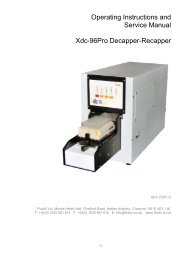
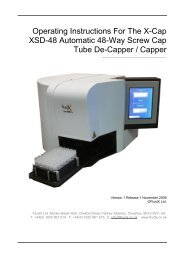
Operating Instructions For The<strong>XSD</strong>-<strong>96Pro</strong> 96-Way Screw CapTube De-Capper / Capper__________________________________Version 1 Release 1 November 2009©<strong>FluidX</strong> Ltd.<strong>FluidX</strong> Ltd. Monks Heath Hall, Chelford Road, Nether Alderley, Cheshire, SK10 4SY, UK.T: +44(0) 1625 861 614 F: +44(0) 1625 861 615 E: info@fluidx.co.ukwww.fluidx.co.uk1 Operating instructions for the X-Seal Plate Piercing System
This document is for information only; the manufacturer accepts no liability forerrors contained herein or for incidental or consequential damages with thefurnishing, performance, or use of this material.Unless otherwise specified references to names or parts is purely casual and hasthe purpose of illustrating the product. The contents of this publication may not bereproduced in any form or by any means (including electronic storage andretrieval or translation into a foreign language) without prior agreement andwritten consent from the copyright owner.The information contained in this document is subject to change without notice.Manufactured for:Manufactured by:fluidX Ltd.Monks Heath HallHelford RoadNether AlderleyCheshireSK10 4SYUKTel: +44 (0) 1625 861 614Fax: +44 (0) 1625 861 615Email: sales@fluidx.co.ukWeb: www.fluidx.co.uk2 Operating instructions for the X-Seal Plate Piercing System
TABLE OF CONTENTS1. INTRODUCTION 4LIMITATIONS ON MACHINE USE 4WARNINGS 4APPLICABLE RULES 5SPECIFICATIONS 52. INSTALLATION 6PRELIMINARY 6VOLTAGE CHECK 63. TOUCH SCREEN CONTROL INTERFACE 7INITIALISATION 7SELECT CORRECT TUBE TYPE 7REMOVE CAPS CYCLE 8REPLACING CAPS CYCLE 9PARKING POWERING DOWN 114. TROUBLESHOUTING 12AFTER DECAPPING CYCLE THE DRAWER MECHANISM WILL NOT OPEN 12NEED TO WASTE CAPS AFTER DECAPPING 12“INSERT RACK TO REPLACE RACK” BUT HAS NO CAPS IN THE UNIT 135. TUBE COMPATABILITY 136. SERIAL COMMUNICATIONS TO <strong>XSD</strong>-96 DECAPPER 14COMMUNICATION PROTOCOL 14COMMANDS STRUCTURE 14COMMANDS SET 15GET STATUS 15EXAMPLES 157. DRAWING 168. DISPOSAL 173 Operating instructions for the X-Seal Plate Piercing System
1. INTRODUCTIONLIMITATIONS ON MACHINE USEThe <strong>XSD</strong>-<strong>96Pro</strong> is designed specifically for use of the 96 format screw cap tubes.The <strong>XSD</strong>-<strong>96Pro</strong> will be pre-configured for the correct tube selection specified at the time ofordering.The <strong>XSD</strong>-<strong>96Pro</strong> is not to be used for any other purpose.WARNINGSBefore use please read the following warnings carefully:This product must only be used in accordance with proper safety standards andprocedures, together with the instructions contained in this manual. The <strong>XSD</strong>-<strong>96Pro</strong> has beendesigned and manufactured to conform to international safety specifications.Users should be aware of the potential hazards associated with the equipment.All operators should read and observe the safety precautions and warnings given in thismanual before using the <strong>XSD</strong>-<strong>96Pro</strong>.If the <strong>XSD</strong>-<strong>96Pro</strong> is used in a way not specified within this manual any inbuilt protection maynot be adequate.The following caution and safety signs are used in this manual:WARNING. Please refer to manual.The machine is designed for indoor laboratory use only, at an altitude of less than 2200mabove the sea level, within a temperature range of 15°C to 35°C and a relative humidityrange of 5% to 85% non condensing. If the instrument is stored outside these ranges, it shouldbe left to stand until it equilibrates to within the above limits.Ensure that the voltage selection switch is set to the correct voltage and that the correctfuse for the required voltage setting is fitted. Do not work outside the rated power supplyrange.Use the cleaning method recommended by the manufacturer.Ensure the unit is only connected to an earthed supply.There are no user accessible or serviceable parts inside the unit. Do not remove the unit‟scabinet.WARNING Risk of electrical shock (high voltage)This equipment should only be dismantled by properly trained personnel, removing the topcase exposes potentially lethal mains voltages.4 Operating instructions for the X-Seal Plate Piercing System
APPLICABLE RULES2006/95/CE2004/108/CE2002/96/CELow Voltage DirectiveElectromagnetic Compatibility Directiveamended 2003/108/CE WEEE DirectiveSPECIFICATIONSMaterialsAll components which can come in contactwith samples are made from Stainless steel,anodized aluminum or resistant plastics. Cabinetprotection grade IP 54.Dimensions W 278mm x D 279mm x H 515mmWeight40kgPower RequirementsAC 110V/230V 6A MaxUser InterfaceColor control touch screen for manual use.Serial Command Set for Remote Integration.Cable InterfaceSerial RS232Temperature range Operative: 18°C - 35°CStorage: -20°C – 40°CRelative humidity20% - 80% not condensing5 Operating instructions for the X-Seal Plate Piercing System
2. INSTALLATIONPRELIMINARYAfter unpacking make sure all packing and fixtures are retained, as the unit must always betransported in the original packing to avoid damage. The manufacturer accepts noresponsibility for damage incurred unless the unit is correctly packed and transported in thisway.Remove the <strong>XSD</strong> unit from its packaging.The <strong>XSD</strong> must be placed on a level surface, away from direct sunlight, ensuring access tothe power switch on the back of the unit. Ensure that the vents on the cabinet are notobstructed.The main voltage selector switch should be checked to ensure that the voltage has beenset at the correct value.Connect the unit to the main power supply and switch on the switch I/O of the rear powerinterface.VOLTAGE CHECKBe sure that the equipment is not connected to the mains power.On the back of the <strong>XSD</strong> there a connection panel with:Power setting 230/115 Vac and fuse holderOn/off power switchMain power plugThe setting voltage is written in white on a red background on the top of power setting andfuse holder. The <strong>XSD</strong> is factory set to 230V.6 Operating instructions for the X-Seal Plate Piercing System
3. TOUCH SCREEN CONTROL INTERFACEINITIALISATIONPower on the systemPlug in the correct mains power lead andtoggle the mains power switch from off to onThe <strong>XSD</strong> will go through it‟s power onInitialisation.While Initialising the Colour Touch Screen willshow:Hardware VersionFirmware VersionSerial NumberAfter succesful Initialisation the system willdisplay the “Ready to begin” menuSELECT CORRECT TUBE TYPEPress the “Main Menu” button to enter the mainmenu screenPress the “Select Rack” buttonPress “Previous Rack” or “Next Rack” to cyclethrough the rack options enabled on yoursystem.The system will be configured for the tube typesselected at time of ordering.For a full list of all compatible tubes see section“TUBE COMPATABILITY”7 Operating instructions for the X-Seal Plate Piercing System
Press the “Use Rack” button to confirm therequired Tube Type.This will reset the system to the requiredparameters and Open the Drawer.When the system has completed the reset, thedrawer will be open and the “Insert rack toremove caps” menu will be shown.REMOVE CAPS CYCLEInsert the correct Tube Type and Rackcombination into the Rack Shuttle DrawerPress the “Remove Caps” button to begin thedecapping cycle8 Operating instructions for the X-Seal Plate Piercing System
The Drawer will closeThe Caps will be removedThe Drawer will openRemove the rack and process as requiredREPLACING CAPS CYCLEInsert the correct Tube Type and Rackcombination into the Rack Shuttle Drawer9 Operating instructions for the X-Seal Plate Piercing System
Press the “Replace Caps” button to begin therecapping cycleThe Drawer will closeThe Caps will be replacedThe Drawer will openRemove the rack and process as required10 Operating instructions for the X-Seal Plate Piercing System
PARKING POWERING DOWNIt is advisable to Park the drawer when thesystem is not in use.This will help to prevent damage to the stage.To Park the <strong>XSD</strong>, press the “Main Menu” buttonPress “Park Drawer”The system will park the drawer mechanism andreturn to the “Ready to begin” screenThe unit may be left like this of powered downby using the mains switch on the rear of the unit.11 Operating instructions for the X-Seal Plate Piercing System
4. TROUBLESHOOTINGAFTER DECAPPING CYCLE THE DRAWER MECHANISM WILL NOT OPENThis is due to one or more caps not beingremoved correctly.The System will automaticaly attempt to recoverfrom this situation by replacing the caps andattempting to remove them again.If the system is not able to auto recover the“Error” screen will be displayedPressing the “Retry” will attempt another recap /decap cycle to clear the error.Pressing “Help” will enable you to do a reset ormove the system to the Service Position.Help Options“Retry” This will attempt the last action again toclear the problem“Reset Machine” This will perform a full systemInitialisation and Reset“Service Position” This will move the decappinghead up to a safe position for the rack to bemanually extractedEnsure the unit has been used with the correcttubes, rack and cap combinationCheck with manufacturer of tubes for themaximum number or decap and recap cycles,this tends to be from 6 to 12 cycles.Ensure none of the caps are cross threaded.NEED TO WASTE CAPS AFTER DECAPPINGAfter the rack has been decapped, replace therack with a deep reagent reservoir, the unit willstart a recapping cycle and eject the caps intothe reservoir.12 Operating instructions for the X-Seal Plate Piercing System
“INSERT RACK TO REPLACE RACK” BUT HAS NO CAPS IN THE UNITPress “Replace Caps” button, the unit will cyclethrough even if no rack is in the drawer andreturn to the “Insert rack to remove caps” menu.Alternatively press “Abort” during the recapcycle and you will be taken to the “Help” screenwhere you can perform a Reset.5. TUBE COMPATABILITYManufacturer Tube Type CompatibilityFLUIDX 1.4ml Fully CompatibleFLUIDX 1.1ml Fully CompatibleFLUIDX 0.75 ml Compatible, due to size and Weight of tubeit is recommended that the “Locked” versionof the tube is used.FLUIDX 0.5ml Compatible with adapter, due to size andWeight of tube the “Locked” version of thetube must be used.If only low height tubes are used then thesystem can be configured to use the 0.5mlwithout an adapter at the expense of the1.4ml tube compatibilityMATRIX 1.4ml Fully CompatibleMATRIX 0.75ml Fully CompatibleNUNC 1.1ml Fully CompatibleNUNC 0.5ml Fully CompatibleMICRONIC 1.4ml Fully CompatibleMICRONIC 1.1ml Fully CompatibleMICRONIC 0.5ml Compatible with adapter, due to size andWeight of tube the “Locked” version of thetube must be used.If only low height tubes are used then thesystem can be configured to use the 0.5mlwithout an adapter at the expense of the1.4ml tube compatibilityABGENE 1.2ml Not CompatibleABGENE 0.5ml Not Compatible13 Operating instructions for the X-Seal Plate Piercing System
6. SERIAL COMMUNICATIONS TO <strong>XSD</strong>-96 DECAPPERThis section describes the remote communication protocol which can be used to control theDecapper.COMMUNICATION PROTOCOLIt is possible, although not mandatory, to communicate with the module via a serialcommunications link. It is anticipated that communication may occur between the decapper anda PC although, provided that the communication protocol is observed, this is not obligatory.Baud rate: 57600Data bits: 8Stop bits: 1Parity:NoneFlow Control:NoneRTS (Pin7) held positive (RS232 spec would say +12V however anything over about 5V will work)DTR (Pin4) held negative (RS232 spec would say -12V however anything over about -5V will work)Note: The optical isolation requires a minute amount of power. This is provided by two unused pinson the serial port. RTS should be held positive. DTR should be held negative.COMMANDS STRUCTUREThe table below shows the protocol that will be used for a communication packet. Command Byte Data Byte Bcc0x1B = Escape character signals start of command0x12 = Indicates that we want to send a remote control instructionCommand Byte – see command set belowData Byte – see command set belowBcc = (u8bit) checksum = sum of all bytes including 0x1B and 0x12, modulo 256Once a data packet is received, the module will generate a response byte: = 0x06 = indicates that the command was successful = 0x15 = indicates that there is a problem – Send a Get status command to determinenature of problem14 Operating instructions for the X-Seal Plate Piercing System
COMMANDS SETCommandCharacterCommandByteData Byte Action RequirementO N/A Open drawer main_state is state_idle (see below)P N/A Park drawer caps_off = False ANDremoving_caps = FalseS rack numberwhere „1‟ = first rack etcSelect rackI N/A Initialisemachinecaps_off = False ANDremoving_caps = Falsecaps_off = False ANDremoving_caps = FalseC N/A Caps on waiting_for_rack_insert ANDrack_inserted = True ANDcaps_off = TrueU N/A Uncap main_state isstate_waiting_for_rack_insert ANDcaps_off = FalseG N/A Get status NoneR N/A Retry main_state is state_handling_errorGET STATUSGet Status command returns the following datapacket:[0] = [1] = 0x1B[2] = main_state – see opposite for details[3] = Boolean value indicating whether caps areoff[4] = Boolean value indicating whetherremoving caps[5] = Boolean value indicating whether rack isinserted[6] = checksum = sum of bytes 1 to 5, modulo256enum main_state{state_idle = 0x01,state_home_pos,state_invalid_memory,state_main_menu,state_selecting_rack,state_parking,state_handling_error,state_recover_power_fail,state_opening_drawer,state_closing_drawer,state_waiting_for_rack_insert,state_removing_caps,state_replacing_caps};EXAMPLESTo uncap the tubes (assuming decapper is in state „state_waiting_for_rack_insert‟ and the caps arenot already off), send:0x1B, 0x12, 0x55, 0x00, 0x82.To select the second rack (providing it is configured to have two or more racks), send:0x1B, 0x12, 0x53, 0x32, 0xB2.15 Operating instructions for the X-Seal Plate Piercing System
7. DRAWING16 Operating instructions for the X-Seal Plate Piercing System
8. DISPOSALAccording to the Directive 2002/95/CE, 2002/96/CE and 2003/108/CE, concerning the restrictionof the use of certain hazardous substances in the electrical and electronic equipment and thewaste disposal.The symbol of the crossed bin shown on the equipment or on its packaging indicates that theproduct is to be collected separately from the other waste. Thereof the user must deliver theequipment to the appropriate collection points for electrical and electronic waste or to his salerepresentative (if new similar equipment is bought). The appropriate separated collectionallows recycling, treatment and disposal of the unit. It reduces negative effects on theenvironment, human health and allows the unit to be recycled where possible. Be aware thatthe abusive disposal of the product causes the application of administrative sanctionsaccording to the laws in force.Please contact your supplier for further information.17 Operating instructions for the X-Seal Plate Piercing System