Create successful ePaper yourself
Turn your PDF publications into a flip-book with our unique Google optimized e-Paper software.
Xsp - 220 DT<br />
Operator <strong>Manual</strong><br />
Document 9967/901 Issue 1
TABLE OF CONTENTS<br />
1 INTRODUCTION .....................................................................................................................5<br />
1.1 Basic Overview of the Xsp-220 DT 5<br />
1.2 About this manual 5<br />
1.3 Summary of steps involved in setting-up and using the instrument 6<br />
2 GLOSSARY.............................................................................................................................7<br />
3 HARDWARE INSTALLATION ................................................................................................9<br />
3.1 Applied Markings 9<br />
3.2 Unpacking the instrument 10<br />
3.3 Packing List 10<br />
3.4 Identifying the main components of the instrument 11<br />
3.5 Levelling the instrument 12<br />
3.5.1 Adjusting the feet ................................................................................................................................................... 12<br />
3.6 Installing the probe & tubing connections 13<br />
3.6.1 Installing the DT probe........................................................................................................................................... 13<br />
3.6.2 Modes of operation................................................................................................................................................. 17<br />
3.6.3 Connecting the System Fluid Bottle (Wet Mode Only) ......................................................................................... 17<br />
3.6.4 Washbowl Tubing connection................................................................................................................................ 17<br />
3.7 Installing the racks 18<br />
3.7.1 Installing the DT Rack ........................................................................................................................................... 19<br />
3.7.2 Installing the Waste Tip Bag Support..................................................................................................................... 19<br />
3.7.3 Installing the Sample & Deepwell Rack................................................................................................................. 20<br />
3.7.4 Electrical Connections............................................................................................................................................ 20<br />
3.7.5 Checking the arm is level ....................................................................................................................................... 20<br />
3.8 Connecting to the power supply 21<br />
3.8.1 Power cord.............................................................................................................................................................. 21<br />
4 SOFTWARE INSTALLATION ...............................................................................................22<br />
4.1 Computer Minimum Specification 22<br />
4.2 Software Overview 22<br />
4.3 Visprog Installation (New Installation) 22<br />
4.4 Application Installation (New Installation) 24<br />
4.4.1 Running Set-up....................................................................................................................................................... 24<br />
4.4.2 File locations .......................................................................................................................................................... 24<br />
4.5 Installing the Configuration Disk 24<br />
4.6 Instrument Configuration 24<br />
4.6.1 Default Configuration............................................................................................................................................. 24<br />
4.6.2 Instrument Type ..................................................................................................................................................... 25<br />
4.6.3 Hardware ................................................................................................................................................................ 25<br />
4.6.4 System.................................................................................................................................................................... 28<br />
4.6.5 Trace....................................................................................................................................................................... 30<br />
4.6.6 Passwords............................................................................................................................................................... 31<br />
4.6.7 Logging .................................................................................................................................................................. 32<br />
4.7 Updating Software 33<br />
4.8 Operating System Settings 33<br />
Document 9967/901 Issue 1
4.8.1 Windows XP Professional...................................................................................................................................... 33<br />
4.8.2 Windows Vista ....................................................................................................................................................... 33<br />
4.9 Dongle installation (USB) 34<br />
4.10 Switching on for the first time 34<br />
5 DEFINING THE AREAS........................................................................................................35<br />
5.1 Overview 35<br />
5.2 Area Files Used by the DT Application 35<br />
5.3 Pre-defined Area Files 36<br />
5.4 To edit a pre-defined Area file 36<br />
5.4.1 Using the Virtual Joystick ...................................................................................................................................... 37<br />
5.4.2 Checking the pre-defined X/Y Coordinates ........................................................................................................... 38<br />
5.4.3 Checking the pre-defined Height Data Z Coordinates............................................................................................ 39<br />
5.4.4 Saving the changes ................................................................................................................................................. 40<br />
5.4.5 Defining the X/Y and Z Coordinates for other Areas............................................................................................. 40<br />
5.4.6 Area Information .................................................................................................................................................... 41<br />
5.4.7 Locations ................................................................................................................................................................ 45<br />
5.4.8 WASHBOWL X/Y Co-ordinates ........................................................................................................................... 46<br />
5.4.9 TIPOFF .................................................................................................................................................................. 46<br />
5.5 Nudge Co-ordinates 48<br />
5.6 Backing up Area Files 48<br />
5.6.1 Liquid Level Following.......................................................................................................................................... 49<br />
5.7 Volume Calculation 50<br />
5.8 Area Definition Terminology 51<br />
6 RUNNING THE XSP 220.......................................................................................................52<br />
6.1 Preparing the Xsp 220 for Use 52<br />
6.2 Loading the RunTime Software 52<br />
6.3 Priming (Wet Mode) 53<br />
6.4 Pre-run checks 53<br />
6.5 Running an Application 53<br />
6.5.1 Archiving................................................................................................................................................................ 54<br />
6.5.2 Archiving with Worklist......................................................................................................................................... 56<br />
6.5.3 Load Samples ......................................................................................................................................................... 56<br />
6.5.4 Load Samples Sequential ....................................................................................................................................... 56<br />
6.6 Processing Started 58<br />
6.6.1 Startup .................................................................................................................................................................... 58<br />
6.6.2 Tip loading ............................................................................................................................................................. 58<br />
6.6.3 Interrupting Processing........................................................................................................................................... 58<br />
6.6.4 Screen Display........................................................................................................................................................ 58<br />
6.7 Pausing and Stopping the Xsp 220 58<br />
7 FAULT FINDING ...................................................................................................................60<br />
7.1 Liquid Handling Fault Finding table 60<br />
7.2 Software Error Messages 62<br />
7.3 Error Logs 62<br />
8 CREATING NEW APPLICATIONS .......................................................................................63<br />
8.1 Overview 63<br />
Document 9967/901 Issue 1
8.2 Configuration Main Menu 63<br />
8.3 Hardware 63<br />
8.3.1 Probe Insertion depth.............................................................................................................................................. 64<br />
8.3.2 Probe Sensitivity .................................................................................................................................................... 64<br />
8.4 Applications 65<br />
8.4.1 Areas ...................................................................................................................................................................... 65<br />
8.4.2 Application Type.................................................................................................................................................... 66<br />
8.4.3 Transfer Type Parameters....................................................................................................................................... 66<br />
8.4.4 LoadSamples Type Parameters .............................................................................................................................. 74<br />
8.5 Data Configuration 75<br />
8.5.1 File Type ................................................................................................................................................................ 75<br />
8.5.2 File Locations......................................................................................................................................................... 76<br />
8.5.3 Worklist Format ..................................................................................................................................................... 77<br />
8.5.4 Well Number Format.............................................................................................................................................. 78<br />
8.6 Saving Changes 79<br />
9 MAINTENANCE AND REPAIRS...........................................................................................80<br />
9.1 Overview 80<br />
9.2 Daily Routine 80<br />
9.2.1 Probe and fluid path tubing .................................................................................................................................... 80<br />
9.2.2 Valve assembly ...................................................................................................................................................... 80<br />
9.2.3 Syringe drive unit ................................................................................................................................................... 80<br />
9.2.4 Lubrication ............................................................................................................................................................. 80<br />
9.2.5 Electrical safety ...................................................................................................................................................... 80<br />
9.3 Cleaning the Instrument 80<br />
9.3.1 Cleansing agents..................................................................................................................................................... 80<br />
9.3.2 Sterilisation............................................................................................................................................................. 80<br />
9.4 Replacing parts 81<br />
9.4.1 Syringe ................................................................................................................................................................... 81<br />
9.4.2 Probe ...................................................................................................................................................................... 81<br />
9.5 Unblocking the DT Probe Sensor Tube 82<br />
10 SPARE PARTS LIST .........................................................................................................83<br />
11 TECHNICAL SPECIFICATION ..........................................................................................84<br />
11.1 Instrument dimensions 84<br />
11.2 Power requirements 84<br />
11.3 Chemical Compatibility 84<br />
12 REGULATORY ISSUES.....................................................................................................85<br />
12.1 Declaration 85<br />
12.2 Environment 85<br />
12.3 WEEE Directive (Directive 2002/96/EC) * 85<br />
12.4 RoHS Directive (2002/95/EC) 85<br />
13 WARRANTY.......................................................................................................................86<br />
14 USEFUL CONTACTS ........................................................................................................87<br />
Document 9967/901 Issue 1
HTZ<br />
Xsp 220 Operator <strong>Manual</strong><br />
1 Introduction<br />
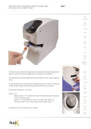
1.1 Basic Overview of the Xsp-220 DT<br />
Disposable Tip<br />
Detect & Eject<br />
block<br />
Archive Plate<br />
Disposable Tip<br />
Rack<br />
96 Position Sample<br />
Rack<br />
Figure 1<br />
The XSP–220 DT sample processor comprises an “XYZ” platform fitted with a single Z drive and an integrated syringe drive<br />
connected to a probe fitted with a disposable tip (DT ) option. The DT option comprises a special block mounted under the arm<br />
that incorporates a Tip Detector and a Tip Ejector block. The Tip Detector is used to confirm that tips are picked up and ejected<br />
correctly during processing.<br />
Pipetting is achieved by means of a special probe that picks up disposable tips via a Tip Adaptor that screws onto the end. The<br />
probe is connected to the syringe by means of the Pipetting Tubing. In operation the pipetting tubing may be filled with air or<br />
distilled water depending on whether the instrument is used in Dry or Wet mode. In either mode, it is the movement of the<br />
syringe piston that causes liquid movement in the disposable tip.<br />
Liquid level detection is achieved by means of a special pressure sensor mounted at the back of the instrument. The pressure<br />
changes that occur when a tip moves into liquid are monitored by this sensor. It is connected to the Tip Adaptor by a second<br />
length of tubing (of smaller diameter) that is integrated within the probe called the Probe Sensor Tubing.<br />
The sensitivity of liquid level detection is enhanced by a slow downward movement of the piston during the “Search for Liquid<br />
“ move.<br />
1.2 About this manual<br />
This manual provides details of how to install and operate the Xsp-220. It also includes an overview of how to create the<br />
programs (called protocols) which run the Xsp-220. However, more detailed information is provided within the applications<br />
software itself in the form of on-line help windows.<br />
Document 9967/901 Issue 1
HTZ<br />
Xsp 220 Operator <strong>Manual</strong><br />
1.3 Summary of steps involved in setting-up and using the instrument<br />
The following is an overview of the steps involved in setting up and using the instrument.<br />
1. Unpacking<br />
2. Installing probe, racks, tubing etc<br />
3. Check that instrument and arm are level and adjust if necessary<br />
4. Install Software onto PC (VisProg2, Applications, Configuration disk)<br />
5. Defining Area files<br />
6. Creating an Application<br />
7. Running the Xsp-220<br />
Your supplier will probably have already performed the majority of the set-up procedures so the initial sections may not be<br />
relevant to you other than as a reference.<br />
In addition to sections on the above this manual also includes additional reference sections on maintenance, fault finding and<br />
information on spare parts. For full servicing information please refer to the separate Service <strong>Manual</strong> especially if adjustments<br />
are required.<br />
Document 9967/901 Issue 1
HTZ<br />
Xsp 220 Operator <strong>Manual</strong><br />
2 Glossary<br />
The following is a list of some of the terms used within this manual, which are specific to the Xsp-220 and its software.<br />
Area Definition The process of defining XYZ co-ordinates for any item located within the Working Area<br />
of the instrument<br />
Application This is a flexible program written specifically for a laboratory application.<br />
Software<br />
Area File A file containing XYZ co-ordinates and other data “describing” an item such as a rack on<br />
the instrument so that the Probe can be go to specific positions within that rack<br />
DT Probe An assembly comprising a pipetting needle a pressure sensor tube, a tip adaptor, spring<br />
and locking nut<br />
Level Sensor An electronic circuit which detects liquid when the probe needles are immersed in<br />
conductive liquid or a change of pressure with a disposable tip<br />
Level Sensor A connector that forms part of the probe which connects the probe needles to the level<br />
Plug<br />
sensor circuit<br />
Level Sensor A threaded back of the instrument which connects to the level sensor tubing on the probe<br />
connector<br />
Pipetting Needle The metal needle that is connected to the Syringe Pump<br />
Probe Guide A black clamp which holds the Probe in position in the Z-Rack but allows some<br />
movement.<br />
Probe Nozzle The tapered (narrow) end of a Probe Needle which protrudes from the bottom of the tip<br />
adaptor<br />
Protocol A user definable file containing various parameters which control the execution of an<br />
IFA or ELISA assay.<br />
Rack An item or container that sits on the Working Area of the Xsp 220<br />
System Fluid The liquid that is primed-through the Syringe and Probe and which is used for washing<br />
the Probe. Normally distilled water<br />
System Fluid The glass bottle that supplies the syringe with System Fluid/wash fluid. Filled with<br />
Bottle<br />
System Fluid (PBS or Distilled water). Referred to as the Diluent Bottle in previous<br />
version of this manual.<br />
VisProg2 The System software used for the creation and running of the IFA/ELISA Application<br />
Waste Bottle Glass bottle which collects the waste from the Aspirate Needle<br />
Working Area The area of the Tray that is accessible by the probe<br />
Worklist A file containing information specific for a single batch which specifies which samples in<br />
a rack are to be processed for each Test<br />
Z-Rack<br />
The toothed (geared) metal rod into which the Probe is inserted and which is moved up<br />
and down<br />
Document 9967/901 Issue 1
HTZ<br />
Xsp 220 Operator <strong>Manual</strong><br />
3 Hardware Installation<br />
3.1 Applied Markings<br />
One or more of these labels may be used on your instrument for health and safety reasons. To enable their interpretation<br />
correctly each is explained.<br />
Background colour: yellow<br />
Symbol and outline: black<br />
Meaning:<br />
Caution (refer to accompanying documentation)<br />
Background colour: yellow<br />
Symbol and outline: black<br />
Meaning:<br />
Laser radiation - do not stare into the beam. Class 2 laser product as<br />
defined in IEC 825-1:1993. The radiation is in the wavelength range 400 to<br />
700 nm and eye protection is normally afforded by aversion responses<br />
including the blink reflex.<br />
Background colour: green<br />
Symbol: black<br />
Meaning:<br />
Earth (ground) terminal (IEC 417, No. 5017).<br />
Background colour: green<br />
Symbol and outline: black<br />
Meaning:<br />
Protective conductor terminal (IEC 417, No. 5019).<br />
Alternating current - the frequency (Hz), voltage (V) and current (A) or power<br />
consumption (W or VA) will be specified (IEC 417, No. 5032).<br />
Document 9967/901 Issue 1
HTZ<br />
Xsp 220 Operator <strong>Manual</strong><br />
3.2 Unpacking the instrument<br />
The instrument is shipped in a cardboard shipping case, which has been designed to minimise the possibility of damage during<br />
transit. However, when unpacking the instrument you should check that there is no obvious damage to this box or any of the<br />
contents. If there is any damage you must inform your supplier and relevant shipping agent immediately.<br />
IMPORTANT NOTE<br />
DO NOT LIFT THE INSTRUMENT BY THE ARM!<br />
3.3 Packing List<br />
A packing list (Part # 9967/700) is included with the instrument that is specific to the configuration of instrument. Please check<br />
this carefully to ensure that you have located everything within the box before throwing it away! There are some small<br />
components that may have fallen to the bottom of the containers they are shipped in.<br />
When removing the instrument from the cardboard case do not lift the instrument by the arm. This could damage the instrument<br />
and will, at the very least, affect its alignment.<br />
Document 9967/901 Issue 1
HTZ<br />
Xsp 220 Operator <strong>Manual</strong><br />
3.4 Identifying the main components of the instrument<br />
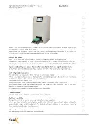
Having carefully unpacked the instrument you will find a number of components in the accessory box. The following<br />
photographs help you identify each of the se components and where they should be located on the instrument. Installation is<br />
mostly straightforward but details of how to install the critical components such as the probe are provided below.<br />
Probe Support<br />
Arm<br />
Probe Guide (9972/502)<br />
Z Rack (9972/260)<br />
Security Bar<br />
Waste Tip Bag<br />
Support<br />
Tip Rack (7030/092)<br />
Deck<br />
Figure 2<br />
Sample and Deep Well<br />
Rack (7030/093)<br />
Guide Rail<br />
Syringe Drive<br />
System Fluid<br />
Bottle<br />
(9972/205)<br />
Figure 3<br />
Washbowl<br />
Document 9967/901 Issue 1
HTZ<br />
Xsp 220 Operator <strong>Manual</strong><br />
3.5 Levelling the instrument<br />
3.5.1 Adjusting the feet<br />
The Xsp 220 is built around a rigid chassis, which rests on 4 adjustable feet. It is designed to be installed on a flat bench but<br />
adjustments can be made if necessary to accommodate a small degree of unevenness.<br />
Looking at the underside of the instrument you should see all 4 feet touching the bench and there should be no “rocking”. If<br />
there is you should adjust the feet by turning one or more feet as required. Tilting the machine back can access these. (Get<br />
someone to help you do this)<br />
The feet on the Xsp 220 have a “click” stop to give a positive location.<br />
Adjustable foot<br />
Figure 4<br />
After levelling the instrument you should then check that the arm is level with respect to the deck. This is easier to do after the<br />
probe has been installed so this will be describer first.<br />
Document 9967/901 Issue 1
HTZ<br />
Xsp 220 Operator <strong>Manual</strong><br />
3.6 Installing the probe & tubing connections<br />
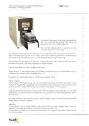
3.6.1 Installing the DT probe<br />
The probe assembly comprises the probe, spring, locking nut and tip adaptor. The probe contains two lengths of tubing of<br />
different diameters. The smaller is used for pressure measurements and the larger is used as a fluidic connection to the syringe..<br />
Probe Tip<br />
Probe Nozzles<br />
Probe Spring<br />
(MME 9357)<br />
DT Probe (9967/201)<br />
Probe Lock Nut<br />
(3427)<br />
Tip Adaptor<br />
(3432DA)<br />
Figure 5 Disposable Tip (DT) Probe and Tip components and Tip Adaptor<br />
Probe Collar<br />
Probe Collar Groove<br />
Probe Guide (9972/502)<br />
Probe Guide Pin<br />
Probe Guide Grubscrew<br />
Z Rack (9972/260)<br />
Figure 6<br />
Install the black probe guide onto the top of the Z rack. Note that the guide pin (Figure 6 ) and grubscrew face towards the back<br />
of the instrument. The grubscrew should be aligned with the indentation at the top rear of the Z rack. It is located at the bottom<br />
of the probe guide – do not install upside down !<br />
Insert the probe into the guide ensuring that the groove in the collar aligns with the guide pin at the rear.<br />
Ensure that the probe is inserted fully into the Z rack and is located at its lowest possible position.<br />
Slide the spring onto the probe and secure with the Locking Nut. Tighten the Lock Nut clockwise until the spring is compressed<br />
by approximately 50% as shown in Figure 7.<br />
Document 9967/901 Issue 1
HTZ<br />
Xsp 220 Operator <strong>Manual</strong><br />
Fluidic Components of<br />
Xsp-220 (Water filled)<br />
Syringe Valve<br />
Pressure Sensor on<br />
back of instrument<br />
Pressure<br />
Sensor<br />
Tube<br />
(Short)<br />
Tip Adaptor<br />
Syringe<br />
Pipetting<br />
Needle<br />
(long)<br />
Pipetting path<br />
Pressure Sensor Path<br />
Disposable Tip<br />
System Fluid<br />
(DI water)<br />
Sample tube<br />
The Fluidic and Sensor path for the XSP-220<br />
Document 9967/901 Issue 1
HTZ<br />
Xsp 220 Operator <strong>Manual</strong><br />
Sensor<br />
nozzle<br />
Pipetting<br />
nozzle<br />
Figure 7<br />
Apply a very small amount of silicone grease onto the thread.<br />
DO NOT ALLOW ANY GREASE TO TOUCH THE NEEDLES AS THIS MAY CAUSE THE LEVEL SENSOR TO FAIL.<br />
Screw the tip adaptor onto the thread.. After approximately 3 turns it will suddenly become much more difficult as the thread on<br />
the adaptor is tapered . From this point you should continue to turn the adaptor by approximately ¾ to 1 turn which will ensure<br />
a good gastight seal. Use some fine emery cloth (P600) or rubber gloves to grip the adaptor if necessary.<br />
Now turn the locking nut anti-clockwise so that it is tight on top of the tip adaptor. The spring should now be fully<br />
uncompressed and the gap between the top of the adaptor and the bottom of the Z rack approximately 12 mm. As shown in<br />
Figure 8.<br />
Figure 8<br />
Document 9967/901 Issue 1
HTZ<br />
Xsp 220 Operator <strong>Manual</strong><br />
Probe Support Rod (6320/040)<br />
Support<br />
block<br />
Figure 9<br />
Screw the connector of the larger diameter tubing into the left-hand port (viewed from the side) of the syringe valve (Figure 11).<br />
This is marked Small Probe.<br />
Screw the connector of the smaller diameter tubing into the Pressure Sensor port on the back panel. (See<br />
Figure 10)<br />
Insert the Probe Support into the Support Block. Adjust the position of the sleeve along the probe so that the probe is supported<br />
as shown in Figure 4. Clip the probe tubing into the loop of the Probe Support, which should be bending towards the front of the<br />
instrument.<br />
Probe Syringe<br />
Tubing<br />
Syringe<br />
RS232 cable<br />
(2020/009)<br />
Probe Pressure<br />
Sensor Tubing<br />
Pressure<br />
Sensor Port<br />
Figure 10<br />
Document 9967/901 Issue 1
HTZ<br />
Xsp 220 Operator <strong>Manual</strong><br />
3.6.2 Modes of operation<br />
There are two methods of operation with the XSP-220 DT and this affects the number of tubing connections required.<br />
When operating in the “Wet” mode, the syringe and probe are primed with distilled water. At various intervals during<br />
processing the probe will pipette a small volume of liquid into a washbowl (if fitted) or a container. A system fluid bottle<br />
supplies the syringe with distilled water.<br />
When operating in “Dry” mode, the syringe and probe tubing are left empty. This simplifies the processing and removes the<br />
requirement for system liquid, associated bottle, Washbowl and waste collection.<br />
“Wet” mode will give the best reproducibility as the amount of air in the system is minimised. “Dry” mode is a slightly simpler<br />
configuration and is more than adequate for pipetting operations where the reproducibility is not critical such as in sample<br />
archiving.<br />
Note that in “Dry” mode although the hydraulic path between the syringe and the probe is left dry, the syringe itself needs to be<br />
lubricated with a small amount of water or Silicone Oil to ensure the pistons do not wear out.<br />
3.6.3 Connecting the System Fluid Bottle (Wet Mode Only)<br />
The System Fluid Bottle (See Figure 3) is connected to the instrument by a single length of tubing terminating in a threaded<br />
syringe connector. This connector should be screwed into the right hand port of the syringe valve. The other end of the tubing<br />
should be inserted through the small hole in the blue cap. There is a short length of rubber sleeving which should be slipped over<br />
the tubing and positioned in contact with the underside of the blue cap. The position of the sleeve should be adjusted so that the<br />
tubing rests on the bottom of the System Fluid Bottle when the cap is in place.<br />
Syringe Valve<br />
(9963/234)<br />
System<br />
Fluid<br />
Tubing<br />
Connector<br />
System Fluid Tubing<br />
Probe Syringe<br />
Tubing<br />
Figure 11<br />
Note: It is not necessary to connect the System Fluid bottle if you are only intending to use “Dry” mode.<br />
3.6.4 Washbowl Tubing connection<br />
The Washbowl is connected to a length of silicone rubber tubing (7600/228). This is installed by pushing it onto the spigot that<br />
protrudes from the washbowl underneath the Deck. Get someone to help you by lifting the instrument up at the front whilst you<br />
fir the tubing.<br />
The other end should be inserted into a waste container such as a 5 litre flask. Note that the waste system relies on gravity so the<br />
path of the tubing should be level or downwards but never upwards or you will get airlocks and the waste will not drain away<br />
correctly.<br />
Document 9967/901 Issue 1
HTZ<br />
Xsp 220 Operator <strong>Manual</strong><br />
3.7 Installing the racks<br />
Each of the racks is located on the bed using one or more rack locators. These engage in a locating hole which is present on the<br />
bottom plate of the rack. The locators are screwed onto the black rail that runs along the front and the back of the deck.<br />
In the DT Applications the following 3 racks are normally supplied as a minimum:<br />
RACK TYPE<br />
Disposable tip Rack Block<br />
Tip Waste Bag Support<br />
Sample/Source rack<br />
Destination rack<br />
NORMAL LOCATION ON DECK<br />
At rear – left or right.<br />
Front left<br />
Middle<br />
Right-hand side<br />
There are a number of variants on each of these rack types. The precise type supplied will depend on the sample tubes and<br />
reagent containers you are using and the positioning on the deck will depend on the application.<br />
When you take the instrument out of the box the locators will normally be fitted to the rail ready to locate your racks.<br />
Do not move the rack locators unless you know you have to e.g. when installing a different type of rack.than the one(s) supplied<br />
with the instrument. Always check that the probe can physically access all the positions in all of your racks before “Defining<br />
Areas”. This is the process, described later, where all the coordinates are defined.<br />
Rack locator<br />
(9972/218)<br />
Locating rail<br />
Figure 12<br />
Document 9967/901 Issue 1
HTZ<br />
Xsp 220 Operator <strong>Manual</strong><br />
3.7.1 Installing the DT Rack<br />
The type of disposable tip rack supplied will depend on what types of tips you intend to use. The rack will usually comprise one<br />
or more locations for either a box of tips or tip refills.<br />
The rack must be located at the back of the instrument using the locking rack locators. These have a washer and screw to allow<br />
the rack to be secured and to prevent it from being lifted by the instrument accidentally during operation.<br />
The photos in Figure 13 show the rack before and after the rack has been secured.<br />
DO NOT OVERTIGHTEN – FINGER TIGHT IS ADEQUATE !<br />
Lockable rack locators<br />
(9967/410)<br />
Figure 13<br />
3.7.2 Installing the Waste Tip Bag Support<br />
Waste Tips are collected in an autoclavable bag which is supported by an adjustable support loop. The base of this unit is fixed<br />
to the locating rail by means of 2 grubscrews. This item will normally need to be fitted as it is not shipped in position. It should<br />
be located at front left or back right location so that the highest part of the loop is nearest an outer edge of the instrument as<br />
shown.in Figure 14<br />
Figure 14<br />
Waste Tip Bag Support (3476) Waste Tip Bags (MME 9361)<br />
Document 9967/901 Issue 1
HTZ<br />
Xsp 220 Operator <strong>Manual</strong><br />
3.7.3 Installing the Sample & Deepwell Rack<br />
This is located on the 2 rack locators on either the front or rear locating rail. The rack comprises 96 sample tube positions and a<br />
single SBS format microplate location at the rear. The 4 black anodised locating bars are adjustable to accommodate the slight<br />
differences in the sizes from different manufacturers.<br />
Rack Locating bars<br />
Adjustment point for<br />
locating bars<br />
Figure 15<br />
3.7.4 Electrical Connections<br />
The power cord may now be fitted into the back of the instrument. Leave the instrument switched off.<br />
Plug in the 25 way end of the RS232 cable into the socket as shown in<br />
Figure 10.<br />
3.7.5 Checking the arm is level<br />
To achieve optimum performance and reliability it is essential that the instrument arm is level. The most critical location is the<br />
disposable tip rack as any differences here can result in unreliable tip operation. It is therefore recommended that you check that<br />
the probe tip is completely level (+/- 0.2mm) with the top of the tip rack across all 96 positions.<br />
1. Make sure the instrument is switched off. When it is switched on the instrument motors are energised and it is<br />
difficult to move the arm manually.<br />
2. Make sure that the tip rack is in position and on its rack locators securely. Ensure that the rack is sitting<br />
absolutely flat on the deck. You may find that if the securing screws that hold the rack down onto the locators<br />
are too tight it may cause the rack to “rock”. These screws only need to be “finger-tight”.<br />
HTZ<br />
Xsp 220 Operator <strong>Manual</strong><br />
5. Move the probe to different positions within the rack and observe any differences in the gap.<br />
6. Compare the distance between the probe and the top of the rack at the front and back and left and right hand<br />
side of the rack. This is best done viewing from the side<br />
If the height difference is >0.4 mm the arm may require realigning or the rack itself may need to be adjusted. You should<br />
consult your service engineer to perform this procedure before defining any areas..<br />
ALWAYS MAKE SURE THE INSTRUMENT AND ARM ARE LEVEL BEFORE DEFINING ANY AREAS<br />
3.8 Connecting to the power supply<br />
Having installed the racks and checked that the instrument is level you may now connect the power cord.<br />
These instruments are fitted with a variable voltage power supply which must be fitted with correctly rated fuses to ensure<br />
maximum protection. The fuse rating is as follows:<br />
115 to 240 Volts - 2 Amp fuse<br />
Note that both neutral and live are fused.<br />
3.8.1 Power cord<br />
Where it is not known what plug type is required the power cord will be supplied without a plug. If this is necessary make the<br />
following connections: -<br />
Live (Line)<br />
Neutral<br />
Earth (Ground)<br />
Brown<br />
Blue<br />
Green/Yellow<br />
It is essential that an earth be connected to any liquid handling equipment, especially if it has a filter fitted. If a fused plug is<br />
used, it requires a 3-amp fuse.<br />
Document 9967/901 Issue 1
HTZ<br />
Xsp 220 Operator <strong>Manual</strong><br />
4 Software Installation<br />
4.1 Computer Minimum Specification<br />
HARDWARE DETAILS COMMENTS<br />
Processor<br />
Pentium II<br />
Processor Speed<br />
500 MHz<br />
Memory (RAM)<br />
64 Mb<br />
Hard Disk<br />
6.4 GB<br />
Optical Drive CD-RW Required for making permanent<br />
backups<br />
Serial Port 1 x RS232 For communication with the<br />
instrument<br />
Sound card (integrated or separate Sound card + speakers Used for audible warnings<br />
card)<br />
Printer<br />
Most should work but For printing of Worklists<br />
should be tested first<br />
OPERATING SYSTEM<br />
Microsoft Windows<br />
XP Professional<br />
(Service Pack 2)<br />
Vista not yet supported<br />
It is also strongly recommended that you incorporate a writeable e.g. CD-RW drive for backup purposes as some of the files are<br />
larger than 1.4 MB. A memory stick may also be used but the files must be archived to a disk so that a permanent record is kept.<br />
It is also recommended that you purchase a printer with a USB connection.<br />
Please note that HTZ only supports the English Language Version of Windows XP. If you are unable to obtain this version or<br />
need to use another language version please contact HTZ first for advice.<br />
4.2 Software Overview<br />
If the PC was supplied with the instrument the software will have been installed and configured at the factory. However, if the<br />
PC was sourced locally it will be necessary to perform the software installation procedure described below.<br />
There are 3 main components to the Xsp 220 Software supplied on 3 CDs:<br />
1. “VisProg System” – the main instrument control software.<br />
2. “Applications Software” – a specific piece of software for an application on this configuration of instrument.<br />
3. “Instrument Configuration” - XYZ calibration data for an individual instrument.<br />
Each of these disks needs to be installed.<br />
4.3 Visprog Installation (New Installation)<br />
1. Insert the disk labelled “VISPROG2 Installation and Set-up” CD into the CD drive of the computer.<br />
2. The program should now automatically load. If it does not, locate and run the SETUP.EXE program located in the root<br />
directory of the CD by selecting the Windows Start button (Start, Run, and Browse).<br />
3. Follow the screen prompts pressing the Next Button when prompted.<br />
Document 9967/901 Issue 1
HTZ<br />
Xsp 220 Operator <strong>Manual</strong><br />
4. Accept the default Program Folders Directory (See Figure 17) and click Next<br />
Figure 17<br />
5. Click Next on the “Start Copying Files” prompt. The Visprog software will now be installed on the computer in the<br />
C:\KWINSP directory.<br />
After re-booting the computer the following 6 icons will be displayed on the desktop.<br />
Figure 18<br />
The 6 programs shown above in the program selection window represent the main VisProg System Software programs. They<br />
have the following functions:<br />
PROGRAM NAME<br />
FUNCTION<br />
CONFIGURATION<br />
Used to set up various instrument and software options such as<br />
password definitions, which Serial Port to use and whether to use the<br />
software on-line or off-line etc.<br />
DIAGNOSE32<br />
This shortcut should be deleted as it is not applicable to this system<br />
RUNTIME32 The program used to actually drive the Xsp 220<br />
GUARDIAN SPREADSHEET<br />
Program used for processing Worklists<br />
SETAREA32<br />
Used for defining the co-ordinates of racks<br />
VISPROG2 (or VISPROG32 on earlier<br />
versions)<br />
Used for creating new applications (requires dongle). This shortcut<br />
should be deleted as it is not applicable to this system<br />
Note that some of the shortcuts refer to programs that are not used by the by this specific instrument and may be deleted.<br />
Document 9967/901 Issue 1
HTZ<br />
Xsp 220 Operator <strong>Manual</strong><br />
4.4 Application Installation (New Installation)<br />
4.4.1 Running Set-up<br />
After installation of the Visprog2 disk you must now install the Application software. Always install the Visprog2 before<br />
installing the Application Disk.<br />
1. Insert the disk labelled Application Disk CD into the CD drive of the computer.<br />
2. Locate and run the Set-up program located on the CD by selecting the Windows Start button (Start, Run, and<br />
Browse) located in the root directory of the CD. Follow the screen prompts pressing the Next Button when<br />
prompted.<br />
3. Accept the default location for files and folders<br />
4. Enter your name and the name of the organisation if prompted to do so.<br />
4.4.2 File locations<br />
The DT Applications software also installs a number of files into the C:\KWINSP directory.<br />
It also creates a directory structure (C:\XSP) for the reading and processing of worklists.<br />
It also installs a directory \Kwinsp\DefaultAreas that contains a set of default Area files (Rack coordinate files). These are<br />
examples and are not instrument specific. You may either create instrument specific Area files using the SETAREA32 program<br />
or you can copy those created at the factory.<br />
4.5 Installing the Configuration Disk<br />
An additional diskette or CD is supplied which contains a number of Area files that have been defined with your specific<br />
instrument during its testing. If this is the first installation of the software these files should be copied into the \KWINSP<br />
directory-using Explorer. Do not perform this step if the Area files in the \kwinsp directory have already been edited to match<br />
your machine.<br />
This diskette will not necessarily contain a full set of all the Areas required by the software - only the ones that are defined and<br />
used during testing.<br />
You may find that these files still need to be “fine tuned” as the positioning of the arm may have moved slightly during transit.<br />
The exact positioning may also be influenced by the flatness of the bench that the Xsp 220 has been installed on.<br />
4.6 Instrument Configuration<br />
4.6.1 Default Configuration<br />
After completing the installation of the software the PC will now be configured to the factory setting. However, it may be<br />
necessary to change one or more of these parameters before the instrument will run correctly. In particular this applies to the<br />
Com Port setting. There are also number of other options you may like to change just to suit your specific requirements.<br />
These changes are made using the Configuration program which is loaded by clicking on the Configuration icon on the desktop.<br />
For completeness this section describes all of the main configuration options that you would need to check if installing without a<br />
factory configuration disk. However, if you have one you can usually just check the Com Port setting and skip the rest as they<br />
should all be correct.<br />
Document 9967/901 Issue 1
HTZ<br />
Xsp 220 Operator <strong>Manual</strong><br />
4.6.2 Instrument Type<br />
Once the configuration program is loaded there are a number of menu options. Select the Instrument Type as “Other Models” in<br />
Figure 19<br />
Figure 19 Instrument Type<br />
4.6.3 Hardware<br />
4.6.3.1 Instrument OnLine<br />
You will be prompted (as shown in Figure 20) to specify whether the instrument is Online or Offline. (This prompt is<br />
the same as is also displayed if you select the Hardware menu option). If you want to drive the Xsp 220 you should<br />
check this box. If you always want to run the PC in simulation mode (useful for checking Protocols without driving<br />
the machine) you should uncheck this option. If the option is checked the software can still be run in offline mode<br />
simply by switching the machine off BEFORE running the software although it takes a few seconds to establish the<br />
instrument is not present.<br />
Figure 20 Instrument Online prompt<br />
Document 9967/901 Issue 1
HTZ<br />
Xsp 220 Operator <strong>Manual</strong><br />
4.6.3.2 Port parameters for Serial Port<br />
Enter the number of the Serial Port of your PC that is being used to drive the instrument. For desktop computers this<br />
is usually Port 1 but it does depend on the computer. For example, many laptops are set at Port 3. Remember which<br />
port you have selected and if the PC has more than one make sure the serial port cable supplied is plugged into the<br />
correct one.<br />
Figure 21<br />
4.6.3.3 Port parameters for USB Port<br />
If your computer does not have an RS232 port you will need to use a USB to RS232 converter (Part# ). These plug<br />
into a USB port on the computer but terminate with an RS232 connector. The Com Port that your PC allocates to this<br />
device can be anywhere between 1 and 15. Check in Windows by looking in the Start > Control panel > System><br />
Hardware > DeviceManager > Ports (Com & LPT). The example below shows COM10 in which case this number<br />
should be used as the Com Port number in the Port Parameters field above.<br />
Figure 22<br />
4.6.3.4 Barcode reader<br />
The tabs labelled “Bar Code Reader”, “Stirrer”, Arm and Incubator are not currently applicable to the Xsp 220 and<br />
you should check that they are configured as not being present. The barcode reader option refers to an integrated<br />
barcode reader mounted on the arm. Note that if you have a wedge type manual barcode reader it is not necessary to<br />
configure this in the HTZ Configuration program as it behaves like an additional keyboard.<br />
Document 9967/901 Issue 1
HTZ<br />
Xsp 220 Operator <strong>Manual</strong><br />
4.6.3.5 Pump<br />
The tab labelled “Pump” defaults to a 1000 ul syringe volume. Make sure that this matches what has been supplied<br />
with the instrument. The DT machine may be supplied with a 2500ul syringe.<br />
4.6.3.6 Security Cover<br />
If you have a Security Cover but do not want the software interlock to operate make sure you choose the second<br />
option. The “No Cover” option should not be used if you have a cover fitted as the additional X movement will drive<br />
the arm into the right-hand cover.<br />
Figure 23 Security Cover Configuration<br />
4.6.3.7 Plate Incubator<br />
Select this option only if your instrument is fitted with the microplate incubator option. If you check the Autorun<br />
option the instrument will switch on the incubator as soon as the Runtime software is loaded.<br />
You will be asked to enter the temperature. This would normally be set at 37°C.<br />
Document 9967/901 Issue 1
HTZ<br />
Xsp 220 Operator <strong>Manual</strong><br />
Figure 24 Incubator Configuration<br />
4.6.4 System<br />
4.6.4.1 Task Bar<br />
The first option on the System Menu is the Task Bar. This controls which of the “Background” programs are<br />
displayed on the Task Bar at the bottom of the screen when the Xsp 220 is running. These background programs are<br />
so called because under normal operation you don’t need to use them. This configuration should therefore normally<br />
be set as shown below:<br />
Figure 25<br />
Document 9967/901 Issue 1
HTZ<br />
Xsp 220 Operator <strong>Manual</strong><br />
4.6.4.2 Sensed Bottle Rack<br />
The Sensed Bottle Rack option relates to a set of special bottles incorporating sensors. These are currently not<br />
available for the Xsp 220 so this option should be unchecked.<br />
4.6.4.3 Display<br />
The “Display “ option configures the colour displayed for various liquid handling errors that may arise during<br />
processing. These colours are displayed when the instrument runs. Although configurable, it is recommended that you<br />
use the default values.<br />
The “No Error” condition should always be configured to be a different colour from the other error conditions.<br />
Figure 26<br />
4.6.4.4 Language<br />
This should be set to “Neutral” for English. No other languages are implemented at present.<br />
Document 9967/901 Issue 1
HTZ<br />
Xsp 220 Operator <strong>Manual</strong><br />
4.6.4.5 Weighing<br />
This option must be unchecked as it is not available for this application.<br />
4.6.5 Trace<br />
Select the Trace options tab. If you want Trace data files to be created for linking to a plate reader then check this Create Trace<br />
Files option. This will create a text file with the extension .ddd in the path specified. Ignore the remaining options (Identifiers,<br />
Database, Miscellaneous etc), as these are currently only relevant to systems incorporating an automated bar-code reader.<br />
Figure 27<br />
Document 9967/901 Issue 1
HTZ<br />
Xsp 220 Operator <strong>Manual</strong><br />
4.6.6 Passwords<br />
When you first install the software onto a PC you will need to login to the password system in order to disable the default<br />
requirement for passwords.<br />
Select Login and enter “supervisor” and “password” in lower case as the <strong>User</strong> Name and Passwords respectively.<br />
Figure 28<br />
Figure 29<br />
You should then get a message to inform you that you are logged in. You may now “uncheck” the “Enable Password Protection”<br />
option.<br />
Figure 30<br />
Document 9967/901 Issue 1
HTZ<br />
Xsp 220 Operator <strong>Manual</strong><br />
4.6.7 Logging<br />
Make sure that both the Link Log and Error Logs are both checked. These instruct the instrument to automatically record<br />
certain messages in a file (eg BEEDRIVE.LOG) which can be used by a product specialist to help find the fault. (See 7.3)<br />
Figure 31<br />
Document 9967/901 Issue 1
HTZ<br />
Xsp 220 Operator <strong>Manual</strong><br />
4.7 Updating Software<br />
If you need to re-install or update the software you will first need to perform an uninstall.<br />
Select Start > Control Panel>Add or Remove Programs<br />
Scroll down and select Visprog2 and then select Remove<br />
After completion repeat and select XSP-220 Applications and select Remove<br />
You may now re-install both sets of software.<br />
4.8 Operating System Settings<br />
4.8.1 Windows XP Professional<br />
If you opt to use certain features in the software such as Excel type spreadsheets as worklists, you will need to ensure that the<br />
Regional and Language settings match those shown in Figure 32 i.e. they need to be set as UK English.<br />
You must also ensure that the settings for the decimal symbol and digit grouping character are in the standard English Language<br />
format (as shown below)<br />
Figure 32<br />
4.8.2 Windows Vista<br />
Not yet supported<br />
Document 9967/901 Issue 1
HTZ<br />
Xsp 220 Operator <strong>Manual</strong><br />
4.9 Dongle installation (USB)<br />
The Applications Software is supplied with a security key or “dongle” (Figure 33) . This needs to be installed in the PC before<br />
the instrument will run the Application provided.<br />
To install a USB security dongle simply plug it into any available USB port. Windows will prompt with the message “Found<br />
new hardware” and will proceed to install the software for the device automatically. You will not need a separate driver disk.<br />
Once completed you may need to reboot the computer to complete the installation.<br />
The dongle is in effect the software license and is very valuable. A replacement will be charged at the full list price of the<br />
software so it is recommended that it is secured to the computer with a security cable as some may assume that it is a memory<br />
stick and remove it.<br />
Figure 33<br />
4.10 Switching on for the first time<br />
The power switch is located at the rear right of the instrument. As soon as the instrument is switched on all motors (X,Y,Z and<br />
pump) will be energised. Depending on the version of firmware installed you instrument may “Home” itself. This refers to the<br />
process whereby all motions return to their 0 reference coordinate. The Home position is set at a position where the arm is at the<br />
extreme left-hand side (X=0) , the Z Rack is at the rear of the arm (Y=0) and the Z rack is in the up position (Z=0). The syringe<br />
will also drive to the top position.<br />
If the instrument sounds as if the motors are struggling to drive one of the motions home and continually drive then switch the<br />
power off immediately. This can happen with the syringe drive if it has been driven manually or pushed up above its home<br />
position in transit. With the power still off move the piston down manually by pushing on the drive plate and switch on again.<br />
If the problem persists consult your service engineer.<br />
Document 9967/901 Issue 1
HTZ<br />
Xsp 220 Operator <strong>Manual</strong><br />
5 Defining the Areas<br />
5.1 Overview<br />
This is the process of entering the co-ordinates for any racks, containers, microplates, etc. that the instrument needs to use –<br />
including the Washbowl, Tip Racks and the Waste Tip position. In outline the process involves moving the probe to certain key<br />
co-ordinates located on the bed and saving the data in a file called an Area File. This data can then be used whenever this item<br />
needs to be accessed by the probe.<br />
Area Definition is performed using the program SetArea (or SetArea32- depending on version) which is loaded by selecting the<br />
icon on the desktop. The end result of the process is the creation of a number of files containing the precise coordinates of the<br />
various racks used by your instrument.<br />
5.2 Area Files Used by the DT Application<br />
The table below lists the default names given to the Areas required by the DT Application. All of these Area files need to be<br />
present in the main sample processor directory (C:\KWINSP). Although these names can be changed it is recommended that you<br />
leave them unaltered until you have familiarised yourself with the Applications software as any changes here also need to be<br />
reflected in the Applications themselves.<br />
A Default copy of all of these will all be installed as part of the software installation procedure so you do not have to create<br />
these from scratch. However, you will at least need to check them and possibly edit them slightly.<br />
AREA NAME ITEM USAGE NOTES<br />
WASHBOWL The washbowl Used for washing the probe when<br />
operating in “Wet” mode<br />
TIP1000 Rack for disposable<br />
tips<br />
Uses to locate either boxed or<br />
refill type tips<br />
DTSAMPLES 96 position tube rack Primary Sample tube rack .<br />
DTDEEPWELL Rack for a deep well<br />
plate<br />
The Washbowl Area Type allows for two<br />
positions to be entered but the Xsp 220 is<br />
fitted with a single position Washbowl<br />
therefore use the same co-ordinate for both<br />
positions<br />
For microplate or other SBS<br />
format item including deep well<br />
storage plates<br />
TIPOFF Waste Tip Bag Support Collecting used tips Usually a single position only<br />
DTTESTPOT<br />
150ml container or<br />
similar<br />
Test Area used for checking<br />
operation of instrument<br />
Used to check the Z Motion is operating<br />
correctly<br />
Document 9967/901 Issue 1
HTZ<br />
Xsp 220 Operator <strong>Manual</strong><br />
5.3 Pre-defined Area Files<br />
When the files on the Configuration Disk are installed a set of pre-defined Area files will be copied into the main software<br />
directory (C:\kwinsp). These are the files used when the instrument was tested in the factory and are specific to your instrument.<br />
It is not essential to use them but it can save some time and it is recommended that you use them initially.<br />
The co-ordinates in these Area files need to be checked and adjusted before operation in case of any small changes that may<br />
have occurred to the instrument during shipping.<br />
5.4 To edit a pre-defined Area file<br />
1. Double click on the SETAREA shortcut already installed on the Desktop -<br />
2. Chose File > Open. This will display a list of the Area Files in the \KWINSP directory.<br />
3. Select the file TIP1000 by highlighting it and by double clicking it.<br />
You will now see a window which (usually) displays 4 separate blocks of data (Figure 34). This is all the information currently<br />
stored on disk for this Area. Another window also appears entitled the Virtual Joystick Figure 35 .This allows you to move the<br />
probe in the direction of the arrow and capture its coordinates in the Area Definition Window.<br />
As an example if you chose TIP1000 you will see something like this:<br />
Currently defined<br />
coordinates as saved in<br />
the Area file<br />
Figure 34<br />
Normally when checking the coordinates of pre-defined Areas you only need to concern yourself with the Height Data and the<br />
X/Y coordinates. The parameters defined in the Area Information and Locations are therefore dealt with later .<br />
Document 9967/901 Issue 1
HTZ<br />
Xsp 220 Operator <strong>Manual</strong><br />
5.4.1 Using the Virtual Joystick<br />
Once the SETAREA program is loaded the instrument can be controlled by the Virtual Joystick. This window allows you to<br />
drive the instrument incrementally in any of the 3 axes simply by pressing on one of the arrow keys with the cursor. The basic<br />
objective of defining or editing the coordinates for the different Areas is achieved by moving the probe, using the Virtual<br />
Joystick, to certain key positions and then recording the X &Y or Z coordinates for the probe in that position.<br />
Pressing this button will enter the<br />
Current Coordinate into the field<br />
where the cursor is positioned<br />
Current X,Y and Z Coordinate i.e.<br />
the probe where it is currently<br />
located<br />
Figure 35<br />
The Virtual Joystick has 8 X/Y control arrows and 2 Z control arrows. The 3 fields below the arrows show the steps recorded by<br />
during the X, Y & Z movements from the start (Home) position. These steps equate to the following linear traverse movements<br />
in millimetres.<br />
i. X Motion: 8 steps equal 1mm of traverse movement<br />
ii. Y Motion: 8 steps equal 1mm of traverse movement<br />
iii. Z Motion: 22.5 steps equal 1mm of up/down movement<br />
Therefore with reference to the example shown in Figure 34 the Z movement from the home position down to the Search<br />
Height is 2081 steps. The actual linear distance moved is therefore 2081 / 22.5 = 92.5 mm approximately<br />
To move the probe, simply move the cursor above one of the arrows and press. The probe will start to move slowly in small<br />
steps in the direction of the arrow. The size of the steps will gradually increase and the probe will accelerate. If you want to<br />
change back to a small movement at any time release the mouse button wait 2 seconds before pressing again. The speed will<br />
now have reduced. Take particular care when approaching a rack that is higher than the current height of the probe. You should<br />
make sure that the probe is moving in small increments.<br />
Document 9967/901 Issue 1
HTZ<br />
Xsp 220 Operator <strong>Manual</strong><br />
5.4.2 Checking the pre-defined X/Y Coordinates<br />
You can drive the instrument to any position on the deck using the arrow buttons. However, when editing a pre-defined Area<br />
you can also move the probe directly in a single move to a specific coordinate. This is useful when you want to quickly check<br />
the coordinates that have already been defined.<br />
1. Move the cursor onto the Coordinate that you want to verify. The number in the field will align to the right when selected.<br />
2. From the Area Definition Menu Bar select Probe > To Current XY<br />
The probe will move to that position but will remain at the Minimum Traverse Height which is usually set at a value of 1.<br />
To make a precise check you will need to move the probe down. You can do this either with the Z Down Arrow on the Virtual<br />
Joystick OR you can highlight a Z Coordinate in the Height Data pane and select the Probe > To Current Z.<br />
To move the probe down, press on the Z Down arrow on the bottom right hand corner of the Virtual Joystick. Be patient – the<br />
acceleration in the Z is slow but be cautious as well as it does accelerate eventually. Again, if in doubt, go slowly and release the<br />
mouse button well before the probe is in danger of crashing into any object<br />
5.4.2.1 Checking the pre-defined X/Y coordinates for the tip rack<br />
Figure 36<br />
You will see that for the TIP1000 Area there are 3 pairs of X/Y coordinates namely:<br />
Start of First Row (X and Y)<br />
End of First Row (X and Y)<br />
End of Last Row (X and Y)<br />
A rectangular array such as the Tip rack, the Samples rack and the Deep Well rack can all be defined by means of 3 X/Y<br />
coordinates. You will see that the Location is defined as having 8 positions per row and 12 rows.<br />
Also notice in the example above that the Y coordinate for the End of First Row is greater (565) than that for the Start of First<br />
Row (61). This means that the Start of First Row has been defined towards the back of the instrument. Remember that the Y<br />
home position (Y=0) is when the probe is at the back.<br />
Document 9967/901 Issue 1
HTZ<br />
Xsp 220 Operator <strong>Manual</strong><br />
.<br />
Start of First Row X= 1728, Y = 61<br />
End of First Row X=1727, Y= 565<br />
End of Last Row X= 2524, Y= 570<br />
Figure 37<br />
When defining the tip rack you should do this with tips in the 3 positions as shown in Figure 37<br />
Select the Start of First Row X field using the mouse cursor.<br />
Drive the probe to the position using the “Probe to Current XY. The probe should be central with respect to the tip.<br />
If you find that the black tip adaptor is not central in the tip then move the probe into the correct position using the Virtual<br />
Joystick. Note that although there is a certain amount of side to side movement in the tip adaptor and Z rack you should ensure<br />
that its average position is in the centre of the tip. Having achieved that press the Fix button to overwrite the existing coordinate.<br />
If no change is noted click the “FIX” button again to check fields have updated correctly.<br />
The fields Start of First Row X and Start of First Row Y will now be updated to show the new values. The cursor will also be<br />
moved automatically to point to the next field indicated. You may use the “Probe to Current XY” to physically move the probe<br />
to this position. Repeat for the process the remaining positions i.e. End of First Row and End of Last Row<br />
5.4.3 Checking the pre-defined Height Data Z Coordinates<br />
Here we are checking that the Z coordinates for a given Area are correct.<br />
You will see that there are 6 Height Data Parameters namely:<br />
Min Traverse Height<br />
Min Clearance Height<br />
Search Height<br />
Dispense Height 1<br />
Dispense Height 2<br />
Min Liquid Height<br />
These control the height at which any are operations performed in this specific Area. The names are only a guide as to how they<br />
are used and are not all relevant to all Areas. For example the Area TIP1000 is used only for picking up tips and it is only the<br />
first 3 that are actually used.<br />
For a full guide on where the heights should be defined for the different Areas refer to Table 1.<br />
Document 9967/901 Issue 1
HTZ<br />
Xsp 220 Operator <strong>Manual</strong><br />
5.4.3.1 Defining the Heights for the tip rack (TIP1000)<br />
The bottom left section of the Area Definition window shows the Height Data. To enter height data for a specific data point<br />
first make sure the cursor is over the relevant field and click it. The current number will shift from the left to the right hand<br />
side of the field and this shows it is ready to receive data from the Virtual Joystick.<br />
For the TIP1000 Area set the Min Traverse and Min Clearance Heights to 1. You can do this just by typing in the number into<br />
both fields. In fact you can enter any coordinate this way.<br />
The Search Height is the height used for picking up the tip and this is critical.<br />
Set the Search Height to a point where the tip adaptor is inserted into a tip and the spring is compressed by approximately 50%<br />
of its original length. If you compress the spring too much you may get Z errors during the Definition process but also during<br />
operation. If you do not insert the tip far enough the tip adaptor may not seal properly and you could get dripping from the tip<br />
and could possibly fall off during a pipetting process.<br />
When the Probe needle is at the correct height press the Fix button on the Virtual Joystick. This records the co-ordinate into<br />
the current field and moves it onto the next field. If you want to skip a field simply click the next field that is required with the<br />
cursor before pressing the Fix button.<br />
A certain amount of trial and error may be required to get the optimum setting for this parameter.<br />
Set Search Height at a height<br />
where the spring is<br />
compressed by approximately<br />
50%<br />
Figure 38<br />
5.4.4 Saving the changes<br />
Having checked and or edited the coordinates in the TIP1000 Area you may now save them.<br />
From the SETAREA Menu bar chose File>Save.<br />
If you want to create another copy or have a modified version then chose SaveAs and give the file a different name.<br />
Note: Area files are stored with a .A02 extension to the filename in the C:\kwinsp folder on the host computer.<br />
5.4.5 Defining the X/Y and Z Coordinates for other Areas<br />
The method just described can be used to check the coordinates for other the Areas. Refer to Table 1 for the information about<br />
what Height to set the probe for each type of Area.<br />
Document 9967/901 Issue 1
HTZ<br />
Xsp 220 Operator <strong>Manual</strong><br />
5.4.6 Area Information<br />
The upper left section of the Area Definition window shows the Area Information. The first field in this section specifies the<br />
Area Format. The Area Format selection will modify the rest of the display, as the Area data required is dependent on the type<br />
of Area being defined. For example, the Washbowl Type requires relatively few data points or parameters other than the coordinates.<br />
Other Formats such as the DTSAMPLES may require one or two more of the following parameters also to be entered.<br />
5.4.6.1 Usage<br />
Must be set to Normal as the other options do not apply to the Xsp 220<br />
5.4.6.2 Area Probe<br />
Must be set to 1, as there is only one probe<br />
5.4.6.3 Effective Diameter<br />
This is the internal diameter of the tube or container.<br />
You should take care when setting this parameter for containers in which the probe will perform an aspiration step. It should<br />
be set to the internal diameter of the tube or bottle where the liquid could be held. This figure is used to calculate what volume<br />
of liquid is in the container. The volume calculation is also dependent on the height at which liquid is found and the Minimum<br />
Liquid Height.<br />
This parameter also determines how fast the probe tracks down during aspiration. The smaller the diameter the further down it<br />
will travel for a given aspiration volume. In practice you may have to set the diameter a little smaller or larger than it actually<br />
is. However, it is most important that whatever you set it to, you check the probe remains in liquid during any aspiration step<br />
from the container. Running a “dummy” assay can usually do this.<br />
Note: This parameter is entered in millimetres<br />
Document 9967/901 Issue 1
HTZ Xsp 220 Operator <strong>Manual</strong><br />
Min<br />
Traverse<br />
Height<br />
Min<br />
Clearance<br />
Height<br />
Search<br />
Height<br />
Dispense<br />
Height 1<br />
Dispense<br />
Height 2<br />
Minimum<br />
Liquid<br />
Height<br />
GENERAL WASHBOWL TIP1000 DTSAMPLES DTDEEPWELL TIPOFF<br />
The height the probe needs to be at Set to clear top With a tip fitted to te Set about 5 mm Set to 2 mm N/A – only uses the Z home<br />
when moving into the Area. i.e. the edge of washbowl adaptor set to a height above the top of above the top of coordinate and the Z Negative<br />
tallest part of the Area. Note that or to 1for approx 5mm above the the sample tubes the Deep well Home (for ejection)<br />
you should usually define this with maximum safety highest part of the rack. or 1<br />
plate or to 1<br />
a tip fitted to the adaptor. For<br />
Safety set to 1.<br />
The height the probe needs to be at<br />
when moving from one position to<br />
another within the Area. For safety<br />
this is usually the same as the Min<br />
Traverse Height<br />
The height the probe starts<br />
searching for liquid from or, if the<br />
level sensor is off , the height from<br />
which it aspirates<br />
The height which the pipetting<br />
needle dispenses from.<br />
Set to height that<br />
probe can move<br />
within washbowl<br />
N/A<br />
Set to same as<br />
Clearance Height<br />
Set to a height approx<br />
5mm above the sample<br />
tube within the rack<br />
This is the Tip Pickup<br />
Height.<br />
Set to a height approx<br />
where the spring is<br />
compressed by<br />
approximately 50 – 60<br />
%<br />
As above As above N/A<br />
Set to the top of<br />
the Dilution<br />
tubes<br />
Set to 0.5mm<br />
above bottom of<br />
tube<br />
N/A N/A Set approximately<br />
2 or 3 mm into the<br />
top of the tube<br />
N/A N/A N/A N/A N/A N/A<br />
The bottom of the tube i.e. where it<br />
should stop looking for liquid. Also<br />
used as the lowest point the probe<br />
should ever go to<br />
N/A N/A Set about 1 mm<br />
above bottom of<br />
tube<br />
Set about 0.5mm<br />
above bottom of<br />
tube<br />
N/A<br />
N/A<br />
N/A<br />
Table 1 Recommended positioning of the probe when defining the Z parameters for different Areas<br />
N/A = Not applicable (i.e. value is not used when processing this Area)<br />
Document 9967/901 Issue 1
HTZ<br />
Xsp 220 Operator <strong>Manual</strong><br />
Height definitions for the Source and Target Area files<br />
1 2 3 4<br />
1. Traverse Height &<br />
Clearance Height<br />
Set approx 5-10 mm above top<br />
of the tube so that probe will<br />
clear tubes when moving<br />
across rack<br />
2. Search Height<br />
Set approx 1-2 mm above<br />
highest possible liquid level in<br />
tube.<br />
3. Dispense Height1<br />
(Not used for Samples)<br />
Set inside tube but above<br />
maximum possible liquid level<br />
5mm<br />
1mm<br />
4. Minimum Liquid Height<br />
Set about 1mm above base of<br />
tube<br />
1mm<br />
Figure 39 Height definition for Source and Target Area Files<br />
Document 9967/901 Issue 1
HTZ<br />
Xsp 220 Operator <strong>Manual</strong><br />
The process described below is with reference to Figure 34 (TIP1000) Area but is applicable to the defining of the co-ordinates<br />
required by any single rectangular array as per a standard test rack or Microplate. but it is applicable to any of the other<br />
rectangular areas such as DTSAMPLES and DTDEEPWELL etc.<br />
5.4.7 Locations<br />
The top right section of the Area Definition window shows Locations<br />
For an array of positions to be defined as a single Location, the distance between the positions within a Row must all be the<br />
same. For Locations with more than 1 row, the distance between all Rows must also be the same, however, the inter-row<br />
distance does not need to be the same as the distance between positions within a Row.<br />
The data that is entered into the remaining two fields “Positions/Row” and “Rows/Location” depend on the size and type of rack<br />
being defined. In the case of the TIP1000 area it is usually defined as a Location with 8 positions/Row and 12 Rows/Location, as<br />
this Area is usually defined as either the rack containing the 96 1.2-ml dilution tubes or as one or more Microplates.<br />
Most of the Areas used by this application are of a Rectangular type with a single location. However, some Areas can have<br />
multiple locations – e.g. a 4 position microplate rack . Each plate has to be defined as an individual location.<br />
5.4.7.1 Inserting a new Location in an Area File<br />
This is performed using the “Insert” Button at the bottom right of the window.<br />
First move to the Location where you want the new Rack Inserted. (If the Area only has a single Location Defined<br />
ignore this step)<br />
Press the Insert Button. This will insert a Rack immediately after the Current Rack. It will default to have the same<br />
number of Positions /Row and Rows/Location as the previous Location. This can be changed manually if required.<br />
If you want to delete a Location select the Rack you want to remove and press the “Delete” button.<br />
Figure 40<br />
You can then define the X/Y coordinates for each location. Note that th Z coordinates are common for all locations within an<br />
Area as it assumes the locations are all at the same height.<br />
Document 9967/901 Issue 1
HTZ<br />
Xsp 220 Operator <strong>Manual</strong><br />
5.4.8 WASHBOWL X/Y Co-ordinates<br />
The Washbowl is usually only used by the Xsp-220 when the instrument is operating in Wet mode.<br />
Only 1 position is required when defining the Washbowl,. Therefore to set-up the area needed move the cursor over to the first<br />
field Flush Position X and click it. Move the probe to the centre of the Washbowl using the Virtual Joystick and press the Fix<br />
button. This will record the co-ordinate for both the X and Y simultaneously and the cursor will move onto the next field named<br />
Rinse Position X. Press the Fix button again to record the same co-ordinate.<br />
Save the data (File > Save)<br />
Figure 41<br />
5.4.9 TIPOFF<br />
The TIPOFF Area is defined as a special Area Format called Tipoff. It only requires a single X/Y coordinate which should<br />
defined immediately above the waste bag. No Z coordinates are required..(see Figure 42)<br />
Document 9967/901 Issue 1
HTZ<br />
Xsp 220 Operator <strong>Manual</strong><br />
Figure 42<br />
Document 9967/901 Issue 1
HTZ<br />
Xsp 220 Operator <strong>Manual</strong><br />
5.5 Nudge Co-ordinates<br />
This option is designed to allow you to apply a change to all of the X and Y co-ordinates in an Area. It is particularly useful if<br />
you are trying to modify the position of the probe within an Area which has a number of locations. It allows you to modify all<br />
locations by the same amount in either the X or Y direction.<br />
The Nudge Co-ordinates option is available from the Area Definition Edit menu. The nudge can be applied to either the X or the<br />
Y co-ordinates and you can select whether it is just the Current Rack or all Racks within the Area that are modified.<br />
Figure 43<br />
5.6 Backing up Area Files<br />
Once defined and checked, the Area files must be backed up onto some removable media such as a CD-ROM. It is also useful to<br />
make a copy in a safe directory on the PC so that they are readily available.<br />
The Area files that need to be backed up are the ones used by the installation and that have been defined for your machine. These<br />
are located in the \Kwinsp directory. These should not be confused with the Default Area files that are located in the<br />
\Kwinsp\DefaultAreas, which are effectively for reference only.<br />
To back up your Area files:<br />
1. Insert a memory stick or blank disk into a USB or CD drive of the PC<br />
2. Load Explorer or My Computer<br />
3. Locate the C:\Kwinsp directory and double click on the directory<br />
4. Click on the Type field to sort out the files by type<br />
5. Find and highlight all the Area files (*.A02)<br />
6. Right click on the mouse and chose the Send to a USB stick or CD-ROM<br />
7. Write the files to the CD<br />
Document 9967/901 Issue 1
HTZ<br />
Xsp 220 Operator <strong>Manual</strong><br />
5.6.1 Liquid Level Following<br />
When aspirating liquid from a container the probe will attempt to “follow” or track the liquid surface as it goes down. The probe<br />
will travel down in a number of discreet steps. The number and size of these steps will depend on:<br />
1. The Aspiration Volume – The larger the volume the greater the number of steps<br />
2. The Effective Diameter – The smaller the diameter the greater the number of steps<br />
3. The Insertion Depth – The greater the specified insertion depth the fewer the number of steps<br />
If aspirating a small volume eg 10 µl from a tube of 10mm internal diameter and with an insertion depth of 1mm the probe will<br />
not need to move down beyond the initial insertion to perform the aspiration. The level change will be less than 0.2mm..<br />
However, if aspirating 200 µl the liquid level will fall by approximately 2.5mm so it will be necessary for the probe to move<br />
down to ensure the needle remains submerged.<br />
Insertion<br />
Depth<br />
4mm<br />
Effective Diameter<br />
in mm<br />
Insertion<br />
Depth<br />
after first<br />
part of<br />
aspiration<br />
= 1 mm<br />
Insertion Depth<br />
4mm<br />
Minimum Liquid Height<br />
LARGE VOLUME ASPIRATION<br />
1 2 3<br />
Figure 44 Liquid Level Following during large volume aspiration<br />
When the instrument calculates that it has to follow liquid, it tracks the liquid down in a number of steps. The size of each step is<br />
controlled by the Insertion Depth specified in the protocol. If this is relatively large, eg 4mm, the pump will be able to aspirate<br />
a larger volume of liquid before the probe needs to moves down. This will tend to increase the speed of processing. The<br />
disadvantage is that a larger proportion of the needle’s exterior surface will become contaminated.<br />
Note that the depth is maintained at a minimum of 75% of the original insertion depth.<br />
Figure 44 shows the probe movements during a large aspiration volume.<br />
Document 9967/901 Issue 1
HTZ<br />
Xsp 220 Operator <strong>Manual</strong><br />
1. This shows the probe needle at the specified insertion depth prior to aspiration<br />
2. Shows the liquid level after the first aspiration. Note that the probe remains 1mm beneath the surface.<br />
3. The probe then moves down again to a depth of 4mm and is ready to aspirate more liquid.<br />
Note that if the distance between the Minimum Liquid Height and the current probe height is at any point less than the specified<br />
Insertion Depth, the instrument will give an Insufficient Volume error. In order to minimise the “Dead Volume” the insertion<br />
depth should be reduced to a minimum. However, be aware that aspirating a large volume with a small Insertion Depth increases<br />
the number of Steps required to perform the aspiration so it will reduce the throughput.<br />
5.6.1.1 Tapered tubes<br />
WARNING<br />
When the internal diameter of a tube is smaller at the bottom than the top of the tube it is important to check that the probe<br />
remains beneath the liquid surface during the entire aspiration step, whatever the initial liquid level. This can be checked using<br />
the Utilities – Function Checks – Liquid Following Test.<br />
5.7 Volume Calculation<br />
VOLUME CALCULATION<br />
The volume of liquid in a tube is<br />
calculated as follows:<br />
Volume of a cylinder = π r 2 h<br />
Where r = Effective Diameter / 2<br />
and h = Calculated Depth<br />
and Calculated Depth = Liquid Height –<br />
Insertion Depth<br />
Liquid Height<br />
Calculated<br />
Depth<br />
Insertion Depth (mm)<br />
Calculated Volume<br />
Many tubes have a larger diameter at<br />
the top compared to the bottom. It is<br />
important to enter a value for the<br />
Effective Diameter which is<br />
representative of the tube. If in doubt<br />
use a smaller diameter. This will help to<br />
ensure that the probe needles will<br />
remain under the surface of liquid<br />
during the aspiration<br />
Effective Diameter as specified in Area File(mm)<br />
Minimum Liquid Height<br />
“Dead” Volume<br />
Figure 45<br />
Document 9967/901 Issue 1
HTZ<br />
Xsp 220 Operator <strong>Manual</strong><br />
5.8 Area Definition Terminology<br />
The following is a glossary of some of the terminology specific to the Area Definition process.<br />
TERM<br />
Area<br />
Area File<br />
DESCRIPTION<br />
An item on the bed which needs to be accessed by the probe e.g. a rack, reagent bottle or the washbowl<br />
A file containing the XYZ co-ordinates which defines how the machine will use an Area.<br />
An Area File will contain a set of 1 or more XY co-ordinates, which define 1 or more positions where<br />
each position can be used in the same way.<br />
An Area file may be used by more than one protocol to access the same rack for different processes<br />
provided that they can be performed at the same set of XYZ co-ordinates.<br />
Area<br />
Format<br />
Location<br />
Rack<br />
Row<br />
A rack may be defined with more than one Area file so that it can be used for different functions if the coordinates<br />
are not identical. An example of this is where one process may require the probe to pipette at the<br />
bottom of a rack at the centre of a tube and another may require it to pipette at the top of the same rack<br />
and close to edge of the tube. This would require two separate Area Files to be defined for the same<br />
physical rack<br />
This describes the basic shape or configuration of the rack. Options include Rectangular (e.g. test tube<br />
rack or an array of reagent bottles), Singleton (a single reagent bottle), plus other specials such as<br />
Washbowl. Most Areas can be defined as variants of the Rectangular format.<br />
A part of an Area comprising one or more positions or rows. Depending on the complexity of the rack<br />
being defined an Area may consist of one Location or multiple Locations. An array of positions can only<br />
be defined as a single location if the following is true:<br />
The distance between each position within a row is the same<br />
The distance between each row (if more than 1) is the same<br />
The required sequence of processing (i.e. direction) for each row is the same<br />
An item designed to hold one or more containers, test plates, slides etc. If an Area contains multiple<br />
locations these are numbered as Rack 1, Rack 2, Rack 3 etc<br />
The line of positions in a Location that defines the order in which the positions are processed. Processing<br />
normally proceeds in the direction of whatever is defined as a row. When it reaches the end of one row it<br />
normally proceeds to the beginning of the next row. See Page & Snake sequence below.<br />
Some Locations may only have one Row in which case the end of the first row and the end of the last row<br />
are defined as the same co-ordinate.<br />
When defining a Location you will need to specify the number of positions in a row and the number of<br />
rows per Location. When defining an Area with Multiple Locations these numbers will need to be defined<br />
for each Location.<br />
Virtual<br />
Joystick<br />
The software tool that allows you to move the probe to anywhere on the bed using the mouse.<br />
Document 9967/901 Issue 1
HTZ<br />
Xsp 220 Operator <strong>Manual</strong><br />
6 Running the Xsp 220<br />
.<br />
6.1 Preparing the Xsp 220 for Use<br />
1. Switch on the power for the Xsp 220 (switch is at rear right-hand side of the instrument). The power switch<br />
for the Xsp 220 is located at the rear right hand-side of the instrument with the instrument facing you. The<br />
green power light on the front panel of the instrument should be illuminated. Switch on the computer and<br />
wait for the software to load<br />
2. If using Wet mode ensure that the System Fluid/Diluent bottle is filled with PBS<br />
3. Ensure the Waste bottle is empty and that the cap is securely tightened. Check that the “Open” gravity<br />
waste bottle (connected to the washbowl) is not full.<br />
4. Make sure that all racks are securely in position and located properly on their rack locators. Pay particular<br />
attention to the Tip rack and ensure that it is positioned properly on its locators and that the ridges on the<br />
green plastic locating tabs are “clicked” into position and are beneath the stainless steel retaining clip.<br />
Must be pushed<br />
down so that it<br />
“clicks” into<br />
position<br />
Figure 46<br />
5. Double click on the Run Xsp 220 icon. This loads the “RunTime” software that drives the instrument.<br />
6. From the Protocols Menu at the top of the screen select the Start of Day option. This is used to prime up the<br />
instrument with Diluent – usually PBS. Follow the screen prompts. Whilst the instrument is priming check<br />
that the syringe on the left-hand side of the instrument is filling with diluent and that there are no large air<br />
bubbles present. The instrument is now ready to run.<br />
6.2 Loading the RunTime Software<br />
Load the Runtime software by selecting the Runtime32 icon on the desktop.<br />
This will load the software that drives the Xsp 220. The arm and syringe should home themselves at this point - if they are not<br />
already there. Note that the syringe may take several seconds to home itself if the instrument has previously been switched off<br />
with the syringe at the bottom of its stroke.<br />
Document 9967/901 Issue 1
HTZ<br />
Xsp 220 Operator <strong>Manual</strong><br />
Figure 47<br />
You will now be able to run a Protocol by selecting it from the Protocols menu shown at the top left of the screen.<br />
6.3 Priming (Wet Mode)<br />
At the beginning of the day you should run the Prime Option. This will ensure that the syringe and probe are fully primed with<br />
System Fluid. It is not necessary to prime if using Dry Mode.<br />
6.4 Pre-run checks<br />
Whenever running the instrument you should check that the:<br />
• System Fluid Bottle has been filled (Wet mode only)<br />
• Racks are all located properly and pushed down onto their locators<br />
• New tips are loaded<br />
• Gravity waste bottle is empty (Wet mode only)<br />
6.5 Running an Application<br />
To run an Application from the Initial Runtime screen (Figure 47)<br />
Runtime > Protocols menu<br />
Select the XSP-220 Applications option<br />
You should now have a menu that looks like Figure 48<br />
Document 9967/901 Issue 1
HTZ<br />
Xsp 220 Operator <strong>Manual</strong><br />
Figure 48<br />
Additional applications options may also be displayed.<br />
All the applications provided are associated with the pipetting of samples from a source rack to an Archive plate.<br />
Each one is described<br />
6.5.1 Archiving<br />
If you select the Archiving application you will first be prompted to enter the number of samples you want to process:<br />
Figure 49<br />
Next you will be prompted (Figure 50 ) to enter the name of the data file that will store all the data associated with this run.<br />
A default name will be displayed comprising the letters RUN + a the current time and date stamp (year,month,day,<br />
hour,minutes,seconds). The default name is designed to be automatically unique and easily ordered when searching in Explorer<br />
with respect to the time the file was created.<br />
Document 9967/901 Issue 1
HTZ<br />
Xsp 220 Operator <strong>Manual</strong><br />
Figure 50<br />
You will then be prompted to enter the barcode of the sample tubes. It is best to do this as you load each sample into the XSP-<br />
220 rack. The display also shows a representation of the rack with a pointer indicating the position of the next tube to be read.<br />
You should enter the barcode using the “Wedge” reader or if damaged you may enter it manually.<br />
To go back to the previous position simply enter a blank ID.<br />
Figure 51<br />
Finally you will be asked to asked to ACCEPT the entries and you will then be prompted to load both the target tubes and<br />
Source tubes (Figure 52)<br />
Figure 52<br />
Document 9967/901 Issue 1
HTZ<br />
Xsp 220 Operator <strong>Manual</strong><br />
6.5.2 Archiving with Worklist<br />
In this application the source tube identifiers are obtained from a separate file (CSV or XLS).<br />
You will be prompted to specify the Worklist located in the C:\XSP\Pending directory that contains the barcodes for the samples<br />
you are about to process. You will not be prompted for the number of samples as this is specified within the file.<br />
The processing information is also added to this file so you will not be prompted for “A name of data file to create”<br />
Other prompts will be as per the Archiving application.<br />
Figure 53<br />
6.5.3 Load Samples<br />
This application is used to create a worklist only. You will be prompted to enter the number of samples and the name of the<br />
worklist file to create. You will then be prompted to enter the barcodes of the individual tubes in the same way as per the<br />
Archiving application (6.5.1). The Worklist file will be saved but will not be processed. To process the Worklist you will need<br />
to run the Archiving with Worklist application.<br />
6.5.4 Load Samples Sequential<br />
This application is also only used for creating a Worklist. Instead of identifying the tubes you will be prompted to enter a “seed”<br />
barcode. This acts as the starting point for a series of identifiers that increment by 1. A code will be automatically generated for<br />
each sample requested and stored in the worklist for processing later.<br />
Figure 54<br />
Document 9967/901 Issue 1
HTZ<br />
Xsp 220 Operator <strong>Manual</strong><br />
The resulting worklist would look like Figure 54 with the SourceID column populated with numbers starting with the number<br />
you entered as the “Seed”.<br />
Figure 55<br />
Document 9967/901 Issue 1
HTZ<br />
Xsp 220 Operator <strong>Manual</strong><br />
6.6 Processing Started<br />
6.6.1 Startup<br />
Once all the parameters required by the application have been entered the instrument the arm and the syringe will go home if<br />
they have not already done so. If there is a tip on the probe it will be ejected into the Waste Tip Bag. The syringe will also prime<br />
itself if required.<br />
6.6.2 Tip loading<br />
The probe will move to the Tip rack and attempt to pickup a tip from position 1. If none is found it will automatically move to<br />
the next position in the rack and try again until it “locates” a tip. The instrument checks that a tip has been loaded by means of<br />
the optical Tip Detector.<br />
If the Tip rack is not installed correctly and the instrument is not able to move down smoothly it may detect a Z error. It will<br />
retry the move 5 times before finally displaying a warning allowing you to correct the fault or abort. If the Area file has been<br />
badly defined you will need to abandon the run, redefine the Area and restart.<br />
If the instrument runs out of tips during processing the operator will be prompted to load more tips.<br />
6.6.3 Interrupting Processing<br />
You may interrupt processing at any time by pressing the STOP button on the screen or the Pause button on the keyboard.<br />
Pressing the key also works.<br />
6.6.4 Screen Display<br />
During processing a large amount of information is available about the processing.<br />
The main screen displays a graphical representation of the deck showing which positions have been processed by means of<br />
coloured circles. If the position has been processed successfully it will show a green circle*. If any errors were encountered it<br />
will display a different colour depending on the error e.g. a red circle if insufficient liquid was detected in the tube.<br />
In addition to the graphical display there are also a number of tabs at the bottom of the screen that record information in a<br />
tabular form throughout the processing.<br />
The tabs include:<br />
Run Details<br />
Liquid handling failures<br />
Activity log<br />
Tube Data<br />
Rack Data<br />
TubeID<br />
TubeStatusShadow<br />
TipData<br />
Basic information on length of time processing the batch<br />
Records any liquid handling failures<br />
Records all processing steps, step by step<br />
This is the Worklist<br />
N/A<br />
N/A<br />
N/A<br />
Pressure measurements recorded during processing<br />
6.7 Pausing and Stopping the Xsp 220<br />
1. Emergency Stop<br />
If it is apparent that the instrument is liable to spill liquid, damage other samples, damage itself or appear to<br />
become out of control then switch OFF the power to the XSP 220 immediately. In less urgent cases proceed<br />
as below.<br />
2. You may pause the instrument at any time by pressing the red STOP button. The instrument<br />
will pause and an option will be displayed which allows you to Abort Processing. If you<br />
want to continue then select the No option.<br />
Document 9967/901 Issue 1
HTZ<br />
Xsp 220 Operator <strong>Manual</strong><br />
3. An alternative way of pausing is to use the F10 function key on the computer keyboard. Press it once and<br />
the machine will pause. Press a second time and the instrument will resume processing.<br />
4. Note that the instrument will always complete the move or processing step it is currently performing before<br />
pausing so it may be a few seconds before it actually stops – especially if it is in the middle of doing a probe<br />
wash.<br />
Document 9967/901 Issue 1
HTZ<br />
Xsp 220 Operator <strong>Manual</strong><br />
7 Fault Finding<br />
7.1 Liquid Handling Fault Finding table<br />
The following table lists some of the common problems that may arise when running the instrument. These are most likely to<br />
occur when the instrument is being used for the first time. Note that the colour of screen error codes (where shown) are the<br />
default values and may differ if the configuration has been customised.<br />
Symptoms and Conditions # Possible Causes Solution<br />
1. Insufficient Sample or<br />
Reagent error but plenty of<br />
liquid present in container.<br />
Probe immerses in liquid to a<br />
depth significantly more than<br />
specified by the application<br />
typically to the bottom of container<br />
i.e. failed to detect the liquid<br />
1<br />
Liquid level detector sensitivity setting is set<br />
too low.<br />
Adjust (i.e. increase ) the level<br />
sensitivity in the DT configuration<br />
program<br />
Pipetting code on screen = Red<br />
Pipetting code in Activity Log =<br />
"Dry" or Insufficient<br />
2 Pressure connector disconnected Connect it!<br />
3 Disposable tips are partially blocked or are Exchange tips for new ones<br />
being reused in a demo<br />
4 Tip not picked up correctly because Search Redefine<br />
Height in tip rack Area not low enough<br />
5 Search Height in Sample or Reagent Area<br />
set very close to or below the liquid level<br />
actually encountered.<br />
6 Tip adaptor badly scored and leaking Replace<br />
7 Pressure sensor tube has become wet.<br />
This can happen if the system runs out of<br />
liquid. when using Wet mode.<br />
Set Search Height higher to give time<br />
for Piston to start moving before<br />
probe encounters liquid<br />
Remove Tip Adaptor and dry off.<br />
Purge pressure system with air using<br />
syringe provided.<br />
2. Insufficient Sample or<br />
Reagent error but plenty of<br />
liquid present in container<br />
Probe immerses into liquid surface<br />
by 1 to 2mm (i.e.by normal<br />
insertion depth)<br />
Pipetting code on screen = Red<br />
Pipetting code in Activity Log =<br />
"Dry" or insufficient<br />
8 Minimum liquid height in Area definition set<br />
too high.<br />
Although liquid surface detected it has<br />
calculated that there is Insufficient Volume<br />
(IV) to perform the aspiration step.<br />
10 Effective Diameter parameter in the Area<br />
definition is set too small.<br />
Although liquid surface detected it has<br />
calculated that there is insufficient liquid to<br />
perform the aspiration step.<br />
11 Level detector sensitivity setting is<br />
borderline and not triggering reliably<br />
Redefine the Area and set the<br />
minimum liquid height to the bottom<br />
of the tube.<br />
Redefine the Area and set the<br />
Effective Diameter closer to the<br />
actual diameter of the container.<br />
Increase sensitivity<br />
Document 9967/901 Issue 1
HTZ<br />
Xsp 220 Operator <strong>Manual</strong><br />
3. Probe stopped before<br />
reaching liquid surface<br />
during a search move<br />
No error generated<br />
Pipetting code on screen = Green<br />
Pipetting code in Activity Log =<br />
"OK"<br />
Probe aspirates air as it "thinks"it<br />
has found liquid.<br />
Subsequently fails to dispense<br />
correct volume<br />
4. Probe stopped before<br />
reaching liquid surface<br />
during a search move<br />
Probe returns to Washbowl as it<br />
has "found liquid" before reaching<br />
the Search Height.<br />
Attempts to retry, fails a second<br />
time and returns to Washbowl<br />
Probe does a "dummy" dispense<br />
and moves onto to aspirate next<br />
sample<br />
Error is generated<br />
Pipetting code on screen = Blue<br />
Pipetting code in Activity Log =<br />
"Wet"<br />
12 Sensitivity may be set too high and the<br />
surface liquid on the needle is triggering the<br />
level detector.<br />
13 Probe has detected liquid on the probe<br />
before reaching the Search Height.<br />
In a Search move the probe moves down<br />
from the Clearance Height to the Search<br />
Height and then commences looking for<br />
liquid. If the level detector is triggered<br />
before reaching the Search Height an error is<br />
generated. The Probe has therefore "found"<br />
liquid before it should have.<br />
The Search Height parameter in the Area<br />
Definition may be set to a lower height than<br />
the maximum possible liquid level for that<br />
container and this particular tube has been<br />
filled above the normal fill level.<br />
Reduce sensitivity of level detector<br />
Redefine the Search Height and<br />
make sure it is above the maximum<br />
possible liquid level that will be<br />
encountered for that Area.<br />
5. Failed to dispense correct<br />
amount of sample or reagent<br />
No error generated<br />
Pippeting code on screen = Green<br />
Pippeting code in Activity Log =<br />
"OK"<br />
Appeared to perform the aspirate<br />
step OK<br />
14 Probe sensitivity has been set too high and<br />
the probe is sensing liquid before the Search<br />
move starts or before it reaches the Search<br />
Height<br />
15 Probe electrical connections or wiring have<br />
been damaged and the probe is producing an<br />
intermittent short circuit.<br />
16 Effective Diameter in Area set too large so<br />
probe not tracking liquid surface correctly.<br />
As probe is not moving fast enough the<br />
probe ends up aspirating air<br />
Adjust probe sensitivity<br />
Replace probe<br />
Redefine Area and make sure probe<br />
remains under surface of liquid<br />
throughout the aspirate step.<br />
17 Aspirate speed set too high, not giving probe<br />
enough time for aspirated liquid to enter tip<br />
18 Froth on top of diluted sample causing probe<br />
to aspirate air<br />
Check value for Aspirate speed in the<br />
protocol. This value should be 50.<br />
6. Bubbles on top of samples 19 Dispense speed too high Reduce dispense speed and introduce<br />
mixing step to achieve homogeneity<br />
20 Dispense height too high Lower Dispense Height for the Area<br />
Document 9967/901 Issue 1
HTZ<br />
Xsp 220 Operator <strong>Manual</strong><br />
file<br />
7. Droplets on tip of probe 22 Syringe tip is worn Change the syringe tip<br />
23 Syringe connectors not tight or 1 of the<br />
teflon washers is missing<br />
24 Syringe valve is leaking (rare on new<br />
instruments)<br />
8. Washbowl flooding 25 Waste tubing has a kink or loop in it or<br />
bottle is full<br />
Check that the white teflon washer is<br />
present in those ports which require<br />
one.<br />
Replace valve<br />
Ensure that the gravity waste tubing<br />
can drain freely into a waste bottle.<br />
Ensure that the tubing runs<br />
“downhill” all the way to the mouth<br />
of the bottle.<br />
7.2 Software Error Messages<br />
Area not found<br />
One of the Area files is missing when you try to run the applications software. If it is you will need to copy the Area file from<br />
the \kwinsp\defaultareas directory into the \kwinsp directory.<br />
.<br />
Runtime System Error: Failed to evaluate an expression - Bad Syntax in the following formula: 1<br />
This arises when trying to run some Applications with the wrong Regional Number Settings.<br />
Failed to communicate with instrument – Switching to Off Line mode<br />
Instrument is not connected to computer or it is powered off. Incorrect Port setting in configuration.<br />
Z Error<br />
Occurs when probe has been unable to reach the destination programmed. This may be because of an obstruction. Can occur if<br />
Search Height is set too low in the Tip rack Area.<br />
7.3 Error Logs<br />
A number of “log files” are created to record specific errors if generated during processing. Make sure that the logging option is<br />
selected in the Configuration program. (See 4.6.7)<br />
The log files are :<br />
Beedrive.log<br />
Runtime32.log<br />
SetArea32.log<br />
Runtime.log<br />
If you encounter an error during processing your supplier may ask you for a copy of these files. They are all located in the<br />
C:\kwinsp directory. You can locate and group them together using Windows Explorer and by clicking on the Type tab on the<br />
top right hand screen and looking for Text files.<br />
The most useful is the Beedrive.log which is overwritten each time the Runtime software is loaded. If you do encounter an error<br />
during processing you must make a copy of this file before running the instrument again.<br />
All of the log files are text documents and can be opened in Notepad.<br />
Document 9967/901 Issue 1
HTZ<br />
Xsp 220 Operator <strong>Manual</strong><br />
8 Creating New Applications<br />
8.1 Overview<br />
The XSP-220 is provided with two programmable applications used for transferring samples and creating worklists.<br />
Each of these can be configured to meet your specific requirements by modifying a number of parameters using the<br />
Configuration Application. This also allows a number of Hardware and Data options to be configured. Note that this not the<br />
same program as the Instrument Configuration program described earlier in section 4.6.<br />
8.2 Configuration Main Menu<br />
From the Runtime Main Menu select the Protocols > XSP-220 Configuration option. You will now have options as shown in<br />
Figure 56. The Hardware options allows you to configure certain global parameters that will affect all applications. The<br />
Applications option allows you to edit and create new Applications. The Data option allows you to configure parameters<br />
associated with the file handling e.g. worklists.<br />
Figure 56<br />
8.3 Hardware<br />
Selecting the Hardware button will display the following options shown in Figure 57<br />
Figure 57<br />
Document 9967/901 Issue 1
HTZ<br />
Xsp 220 Operator <strong>Manual</strong><br />
8.3.1 Probe Insertion depth<br />
The Probe Insertion Depth controls how deep the probe will insert under the surface of liquid once it has detected liquid.<br />
Setting this value will ensure that the wetting of tip is minimised and will help accuracy, reproducibility.<br />
However, if accuracy and precision performance is not too critical a larger insertion such as 3mm will allow the instrument to<br />
process more quickly.<br />
Figure 58<br />
8.3.2 Probe Sensitivity<br />
The sensitivity of the level detector can be tuned by adjusting the speed of the syringe and Z drive during a Search move.<br />
A value of 125 works with a 2500ul syringe but can be adjusted here if necessary.<br />
Figure 59<br />
Document 9967/901 Issue 1
HTZ<br />
Xsp 220 Operator <strong>Manual</strong><br />
8.4 Applications<br />
Selecting the Applications button shown in Figure 56 will display the window shown below.<br />
This window allows you to modify the parameters for each of the existing applications and also to create new applications.<br />
The Navigate buttons allow you to select any of the Applications already defined in a list.<br />
The Add After button allows you to create a new Application immediately after the current position in the list<br />
The Move Down and Move Up button allows you to move an application so that it appears in a different position in the list. This<br />
is useful if you want the most commonly used application to appear at the top of the list displayed during processing (see Figure<br />
48)<br />
Figure 60<br />
8.4.1 Areas<br />
Selecting the Areas button displays a screen allowing you to specify which Area files contain the coordinates of the racks you<br />
are using. Currently the Application uses only the Areas specified in the Liquid Handling 1 Source and Target fields. To change<br />
the Areas used select the Change button and navigate to the Area file you require.<br />
Figure 61<br />
Document 9967/901 Issue 1
HTZ<br />
Xsp 220 Operator <strong>Manual</strong><br />
8.4.2 Application Type<br />
When creating a new application by using the Add After button you will be asked to specify the Application Type.<br />
There are currently 2 Application types namely the Transfer Type and the LoadSamples Type. To select a differentType press<br />
the Arrow keys.<br />
Figure 62<br />
Having selected a Type you will be prompted to give it a name. You will then be able to edit the parameters for your new<br />
application.<br />
To save a new application choose Exit followed by Save and Exit.<br />
Note that if you have not changed any parameters from their initial default the application will not be saved.<br />
8.4.3 Transfer Type Parameters<br />
8.4.3.1 Volume specification method<br />
This specifies where the volume to be pipetted is controlled.<br />
Enter 0 to specify within the application – avoids the user having to enter it each time but cannot be changed<br />
Enter 1 to allow user to specify volume when application is run<br />
Enter 2 to read the volume from a worklist. This would allow a different volume to be pipetted for each sample<br />
Enter your choice and select the right arrow button to move onto the next parameter<br />
Figure 63<br />
8.4.3.2 Default volume to be transferred<br />
Document 9967/901 Issue 1
HTZ<br />
Xsp 220 Operator <strong>Manual</strong><br />
The application will default to pipetting the volume specified here. If the previous option (8.4.3.1) is set to 1 the initial volume<br />
displayed by the prompt requesting the volume at Runtime will be set to this value.<br />
Figure 64<br />
8.4.3.3 Liquid Sensing<br />
This controls how the level detector is used during the Sample Aspiration process.<br />
Enter 0 to disable the level detector. The probe would aspirate from the Search Height.<br />
Enter 1 to use the level detector on each visit to an individual position.<br />
Enter 2 to only use the level detector on the first visit to that tube<br />
Normally this should be set to 1<br />
Figure 65<br />
8.4.3.4 Action if insufficient volume<br />
This controls what happens if the volume calculated to be in the tube is less than the volume specified by the Default Volume.<br />
Enter 0 to ignore the sample<br />
Enter 1 to pipette as much as possible . In this case the probe will go down to the bottom of the tube (Minimum Liquid Height)<br />
and aspirate the Default Volume. If the volume is actually less than that required some air will be introduced into the tip.<br />
Note that the Minimum Liquid Height should always be at least 1mm above the bottom of the tube to prevent it from being<br />
completely blocked in this situation.<br />
Document 9967/901 Issue 1
HTZ<br />
Xsp 220 Operator <strong>Manual</strong><br />
Figure 66<br />
Document 9967/901 Issue 1
HTZ<br />
Xsp 220 Operator <strong>Manual</strong><br />
8.4.3.5 Disposable tip blow out volume<br />
This field controls the amount of air used to blow the source liquid out of the tip to ensure complete ejection of the volume<br />
aspirated.<br />
If using Wet mode 50ul is usually sufficient. If Dry then use a value of 100ul.<br />
Figure 67<br />
8.4.3.6 Flush volume<br />
The Flush volume resets the liquid column in the probe when using the Wet mode. This prevents any bubbles from breaking<br />
up during processing which may cause a change in the performance. The volume specified here is dispensed out of the probe<br />
in between each sample and is typically set to around 200ul.<br />
If using Dry mode this should be set to 0 in which case the probe will not visit the Washbowl – except in certain error<br />
conditions.<br />
Figure 68<br />
Document 9967/901 Issue 1
HTZ<br />
Xsp 220 Operator <strong>Manual</strong><br />
8.4.3.7 Source Position flag<br />
This controls the sequence of processing in the Source tube rack<br />
If set to 0 the tubes will be processed strictly in the position sequence in which they occur in the rack eg, 1,2,3,4,5,etc<br />
If set to 1 the sequence is controlled by means of a layout file. A layout file is a simple text file that specifies which positions<br />
will be processed and is useful if a certain number of positions are always omitted eg the first row of a rack or perhaps the first<br />
postion in every row.<br />
If set to 2 the sequence of positions will be read from a specific field within the Worklist. This allows the sequence to be<br />
different for every batch if required.<br />
Layout File Option not yet implemented<br />
Figure 69<br />
8.4.3.8 Target Position Flag<br />
This is analogous to the Source Position flag and controls the sequence of positions in the Target rack<br />
For archiving this would usually be set to 0 i.e. samples loaded into sequential positions.<br />
Document 9967/901 Issue 1
HTZ<br />
Xsp 220 Operator <strong>Manual</strong><br />
8.4.3.9 Full path of layout file<br />
If a layout file is specified for either the Source or Target positions you should enter the name of the file here<br />
e.g. C:\XSP\layouts\layout1.txt<br />
Figure 70<br />
8.4.3.10 Leave space if cannot process<br />
This controls what happens to the loading of the Target rack in the event it encounters a tube which it cannot pipette e.g. if<br />
there was no liquid detected in the tube. The value you chose will depend on whether you always want to maintain the same<br />
sequence in both Source and Target. Another reason is that you might always want the option of trying to manually pipette<br />
some sample into the archive plate.<br />
Set to 0 if you do not want an empty position<br />
Set to 1 to leave a space in the target rack (normal)<br />
Figure 71<br />
Document 9967/901 Issue 1
HTZ<br />
Xsp 220 Operator <strong>Manual</strong><br />
8.4.3.11 Source and Target Areas overlap<br />
Leave this set to No.<br />
Figure 72<br />
8.4.3.12 Barcoded source tube search flag<br />
This option apples if an automatic barcode reader is installed on the instrument.<br />
It allows you to instruct the instrument whether or not to search for a tube within a rack if it is not in its expected location.<br />
You should set this 0 for the XSP-220.<br />
Figure 73<br />
8.4.3.13 Worklist flag<br />
This controls the use of a worklist<br />
Enter 0 if no worklist is to be created<br />
Enter 1 to create a worklist during execution<br />
Enter 2 to use an existing worklist. If you use the same worklist more than once it will simply overwrite any existing data.<br />
Document 9967/901 Issue 1
HTZ<br />
Xsp 220 Operator <strong>Manual</strong><br />
Figure 74<br />
8.4.3.14 Method of creating sample ID<br />
This controls how the sample identifiers will be created.<br />
If set to 0 it will create a series of sequential numbers. You will be prompted to enter a starting number called a “seed” and the<br />
rest of the series will be created by adding 1 to it<br />
If set to 1 you will be prompted to enter a barcode which can be achieved by means of a Wedge reader or keyboard entry.<br />
You will not be prompted to enter codes if using an existing Worklist<br />
Figure 75<br />
8.4.3.15 Record actual volume transferred<br />
This controls whether the volume transferred is recorded in the Worklist or not.<br />
Enter 0 not to record the volume<br />
Enter 1 to record the volume that was actually pipetted. If the volume is less than the volume that was specified it will record<br />
the volume that it has calculated was in the tube as this is also what it will attempt to transfer.<br />
Note that as most tubes (especially plastic ones) are tapered and the calculation assumes a straight walled cylinder ( ) this will<br />
only be approximate.<br />
Document 9967/901 Issue 1
HTZ<br />
Xsp 220 Operator <strong>Manual</strong><br />
Figure 76<br />
8.4.4 LoadSamples Type Parameters<br />
The Load Samples type application is used only for the creation of a Worklist containing sample identifiers.<br />
Curently there is only a single parameter to enter for this application.<br />
The identifiers can be created either based on a sequential series or using a barcode reader as described already for the Transfer<br />
application (8.4.3.14).<br />
Figure 77<br />
To Save choose Save followed by Save and Exit. There may be a long pause whilst it writes the files.<br />
Document 9967/901 Issue 1
HTZ<br />
Xsp 220 Operator <strong>Manual</strong><br />
8.5 Data Configuration<br />
The Data Configuration Menu is used to set up the parameters associated with the Worklist files<br />
Figure 78<br />
8.5.1 File Type<br />
Selecting the File Type button will reveal the following window. The application software works with either Microsoft Excel<br />
or Comma-Separated Variable (CSV) formats. If you wish to change the current setting, click Change. The Change File Type<br />
window will appear:<br />
You may currently specify either Comma separated Variable or XLS as the file type to use.<br />
Figure 79<br />
Document 9967/901 Issue 1
HTZ<br />
Xsp 220 Operator <strong>Manual</strong><br />
Figure 80<br />
Click the button corresponding to the file format you wish to use. Please note that if the Excel format is selected, this will only<br />
work with files in Excel 95 format, and without macros<br />
8.5.2 File Locations<br />
8.5.2.1 Worklists<br />
When an instrument application is run, a worklist is selected from a “pending” folder. During processing, the worklist is<br />
transferred to a “processing” folder, and, on completion, the worklist is transferred from there to a “processed” folder. These 3<br />
folder may be different, two of them may be the same, or all 3 may be the same.<br />
To specify these folders, click File Locations on the Data Configuration menu.<br />
The File Folders window will appear:<br />
Figure 81<br />
To change any one of the folders, click the appropriate Change button A Select Folder dialog will appear:<br />
Document 9967/901 Issue 1
HTZ<br />
Xsp 220 Operator <strong>Manual</strong><br />
Figure 82<br />
Navigate to the folder required and select a file (any file will do) in that folder and then click Open. You will return to the<br />
Folders window with the changed folder denoted.<br />
Note that for this to work, there needs to be a file (even a totally blank one) in the folder, for you to select.<br />
8.5.2.2 Log Files and Layout Files<br />
Here you may also specify the path for the log files and the layout files<br />
8.5.3 Worklist Format<br />
Click Worklist Format on the Data Configuration Menu. The Worklist Format dialog will appear:<br />
This dialog allows you to specify the format used by the worklists (be they Excel or CSV files). The left-hand column gives<br />
the name of the fields as used internally by the XSP-220 software and cannot be changed. The names actually used in the<br />
Worklists can be specified in the Field Name column. The Column No controls the order of the fields in the worklist and in the<br />
example below the Source ID column is the first and Source position is the second. A total of 7 fields has been specified.<br />
Figure 83<br />
Document 9967/901 Issue 1
HTZ<br />
Xsp 220 Operator <strong>Manual</strong><br />
These fields have the following fixed meanings:<br />
Field<br />
Source Rack ID<br />
Source Tube Position<br />
Source Tube ID<br />
Target Rack ID<br />
Target Tube Position<br />
Target Tube ID<br />
Dissolution Volume<br />
Mixing Volume<br />
Mixes<br />
Maximum Aspiration Volume<br />
Transfer Volume<br />
Actual Transfer Volume<br />
Wastage volume<br />
Status<br />
Diluent Position<br />
Reagent Position<br />
Source Tube alias ID<br />
Stream<br />
Meaning<br />
The identifier of a source rack, usually a linear barcode read by the instrument<br />
The position within a given source rack whose tube is to be processed<br />
The identifier of the source tube (typically either a 2D bar code or a linear bar code)<br />
The identifier of a target rack, usually a linear barcode read by the instrument<br />
The position within a given target rack whose tube is to be processed<br />
The identifier of the target tube (typically either a 2D bar code or a linear bar code)<br />
The volume of diluent (microlitres) to be dispensed<br />
The volume of liquid to be aspirated from and dispensed back into a tube during each<br />
individual mix step<br />
The number of mix steps to be performed on each tube<br />
The maximum volume to be aspirated from a source tube when transferring liquid to a<br />
target tube<br />
The volume of liquid to be transferred to the specified target tube<br />
The volume of liquid actually transferred to the target<br />
A text string indicating the status of the operation specified on the current row of the<br />
worklist, typically “PENDING”, “OK” or “ERROR”<br />
The position within the rack specified by the application from where to aspirate diluent<br />
The position within the rack specified by the application from where to aspirate reagent<br />
8.5.4 Well Number Format<br />
Click Well Number Format on the Worklist Configuration Menu. The Well Number Format window will appear:<br />
Figure 84<br />
Document 9967/901 Issue 1
HTZ<br />
Xsp 220 Operator <strong>Manual</strong><br />
8.5.4.1 Source Area Well Number Format<br />
The XSP-220 can handle 3 different formats of microtube rack position or microplate well number:<br />
Numeric – where the positions are numbered from 1 upwards<br />
Alphanumeric – where the positions are “numbered” from A1 to H12<br />
Numeric positions match the way the instrument Areas are defined. For example, a 96 position microplate may have its wells<br />
numbered in 12x8 or 8x12 orientations; the direction of the numbering may be done in various ways as well.<br />
Alphanumeric numbering is assumed to be done in the same way as the conventional numbering of a microplate, with position 1<br />
being “A1”, 12 being “A12” and 96 being “H12”. In fact, the XSP-220 software is capable of distinguishing between numeric<br />
and alphanumeric well number formats in any worklist that is read into the system, so it is only when generating worklists from<br />
scratch, or appending data to an existing worklist, that the software needs to know what format to use.<br />
Figure 85<br />
If you wish to change the well number format from numeric to alphanumeric, or vice-versa, click “Change”. The Change Source<br />
Well Number Format dialog will appear:<br />
Figure 86<br />
:<br />
Click the button corresponding to the format you require. You will return to the Source Well Number Format window:<br />
8.5.4.2 Target Area Well Number Format<br />
This can be specified in exactly the same way as for the Source well number format.<br />
8.6 Saving Changes<br />
Finally when all changes have been made choose the Save and Exit button.<br />
Document 9967/901 Issue 1
HTZ<br />
Xsp 220 Operator <strong>Manual</strong><br />
9 Maintenance and repairs<br />
9.1 Overview<br />
In order to maintain the performance of the sample processor at its optimum level, certain operations are necessary on a daily<br />
basis and others weekly or every fifty to one hundred hours of operation. Refer to Appendix B for recommended maintenance<br />
schedule. It is assumed that spillage will be dealt with immediately and so maintenance of this kind is not scheduled.<br />
The instructions in this chapter must be followed carefully to avoid problems with short-term reliability, the accuracy and<br />
precision of liquid handling and electrical safety.<br />
9.2 Daily Routine<br />
These procedures do not need to be followed if the system liquid is de-ionised or distilled water. If it is, then ignore the daily<br />
tasks concerning the liquid path.<br />
Ensure the Tip Adaptor is wiped clean. You may use isopropyl alcohol. (IPA)<br />
Maintenance<br />
9.2.1 Probe and fluid path tubing<br />
If evidence of a leak is apparent and the valve connectors are acceptably finger tight, it is possible that the flanges on the probe<br />
tube, or system liquid tube might be damaged. When these have been emptied of liquid the connectors can be removed from the<br />
valve and the flanges examined. If anything but a flat round concentric flange is observed this may be the cause of the leak. If<br />
this is the reason the tubing or probe needs to be replaced.<br />
9.2.2 Valve assembly<br />
A very slight leak will not affect performance unduly, but if drips form on the probe when primed in the home position, then the<br />
valve will have to be replaced as soon as possible. Before you reject the valve assembly ensure that the tube connectors are all<br />
finger tight.<br />
9.2.3 Syringe drive unit<br />
Inspect the liquid path for any signs of leakage. Check the junction between the valve / barrel, under the piston seal and at the<br />
base of the barrel. A serious leak in any of these positions will probably require replacement of the syringe unit.<br />
If using Mode 2 (no liquid in probe) you should ensure that there is always a small amount of liquid in the syringe barrel to<br />
lubricate the piston. You may use either water or a few drops of silicone oil. Introduce this into the syringe by first removing it<br />
(see 9.4.1) from the instrument, withdraw the piston and with the barrel upside down add a few drops of liquid into the barrel.<br />
Replace the piston and remove the air from the syringe before installing it back into the syringe drive.<br />
9.2.4 Lubrication<br />
The Z Rack should be inspected every week to see there is any excessive accumulation of debris and residual lubricant.<br />
If it is wipe the smooth surfaces with a cloth soaked in a mild detergent then, using a small brush, clean the gaps between all the<br />
gear teeth to remove as much dirt and debris as possible. After cleaning the Z Rack re-lubricate it by moistening the assembly<br />
with a thin coating (four drops) light machine oil e.g. WD40 or similar. Avoid any excess as this will be taken up by the drive<br />
pinion and thrown outwards, fouling the sensors. If this happens, errors may occur with the Z-motion.<br />
9.2.5 Electrical safety<br />
Periodically inspect the mains lead for damage to the insulation or connections at both ends. If any damage is found, insulate<br />
the damaged area and order a replacement lead as soon as possible.<br />
9.3 Cleaning the Instrument<br />
9.3.1 Cleansing agents<br />
Do not use abrasive cleaning agents, as these will damage painted surfaces. A cloth soaked in a mild detergent solution (refer to<br />
Appendix A for recommended solutions) is the best means of cleaning the painted and stainless steel parts of the instrument.<br />
All surfaces should be routinely cleaned with decontaminating agents.<br />
9.3.2 Sterilisation<br />
Sterilisation of the liquid handling components should be performed regularly, particularly if bio-hazardous materials are being<br />
processed. Please refer to Appendix A for recommended solutions that can be safely passed throughout the liquid path. After<br />
sufficient contact time, the probe(s) should be primed with at least 20ml of de-ionised / distilled water.<br />
Document 9967/901 Issue 1
HTZ<br />
Xsp 220 Operator <strong>Manual</strong><br />
Before performing any maintenance functions on the instrument, ensure that it is completely free of any process-related hazards.<br />
Certification to this effect will be required by anyone handling any parts of the instrument after they have been used. This<br />
applies particularly when servicing is due or when parts are being returned for any reason.<br />
9.4 Replacing parts<br />
9.4.1 Syringe<br />
To replace a syringe you should first ensure that the syringe piston is positioned at the bottom of its stroke. This can be done<br />
using the following method:<br />
If using Wet mode – (if using Dry mode proceed straight to step 1 below)<br />
Remove the System fluid tubing from the diluent bottle<br />
Select the prime option from the RunTime main menu.<br />
Press the Function key 10 when the syringe piston is travelling down.<br />
The piston should stop at the bottom of the stroke.<br />
Next switch off the instrument.<br />
1. Undo the knurled locking ring underneath the syringe drive plate by turning it clockwise (viewed from above)<br />
and then move the piston up into the syringe.<br />
2. Holding the syringe barrel at the top with one hand and the plastic adapter, the syringe is screwed into with the<br />
other unscrew clockwise (viewed from above)<br />
3. If the plastic adapter comes away from the valve with the syringe, then unscrew it from the old syringe.<br />
4. Ensuring that the white adapter teflon washer is still in place inside the adapter, screw it back into the valve<br />
block. Also be aware of a small valve teflon washer which is fitted inside the valve. This sometimes falls out<br />
and will cause leakage around the top of the adapter. (see fig below)<br />
5. Taking the new syringe ensure the piston is pushed into syringe barrel<br />
6. Screw the syringe into the plastic adapter in the valve block<br />
7. Pull the piston rod down and pass the threaded end through the syringe drive plate<br />
8. Screw the knurled locking ring back onto the piston rod<br />
Valve teflon washer Adaptor (9972/501)<br />
Syringe<br />
Barrel<br />
Syringe<br />
Tip<br />
Syringe<br />
Piston<br />
Knurled<br />
Locking Ring<br />
Adaptor teflon<br />
washer<br />
Syringe thread<br />
Kloehn Syringe<br />
insert<br />
Packing Piece<br />
Syringe Unit<br />
9.4.2 Probe<br />
First remove the existing probe. This is the reverse of the installation procedure as described in Section 3.6.1<br />
Next install the probe as per the installation procedure. You should then check that the co-ordinates of the new probe correspond<br />
to the ones currently defined for your system. You can do this using the SETAREA program. Select one of the more critical<br />
Areas such as a Microplate or a Slide Area that has small wells and send the probe to the Clearance Height of the first well.<br />
If the position of the new probe appears to be offset slightly you can do one of the following:<br />
• Redefine the co-ordinates of every Area on your system. This is not quite as bad as it sounds as you can<br />
probably just apply a “nudge” factor in either the X or Y co-ordinates to each of the Areas.<br />
• Physically move the rack locators (to the left or right as appropriate) for all the affected racks along the<br />
locating rails until the rack is in the correct position. This only works if the probe is out of alignment in<br />
the “X” as “Y” adjustment is not possible using this method.<br />
• Bend the probe into the correct position. This is the fastest method but take care not to over bend the<br />
probes. Note that probes are considered to be a “consumable” not covered by the standard warranty.<br />
Document 9967/901 Issue 1
HTZ<br />
Xsp 220 Operator <strong>Manual</strong><br />
The length of the new probe should be within 0.5mm of the old one so for most Areas the Z co-ordinates should not need to be<br />
adjusted. However, for critical Areas such as the disposable tip racks and microplates if the height of the new probe needs<br />
modifying it is best to do this by adjusting the Z co-ordinates for each of the affected files. This can usually be done by<br />
modifying the critical heights by 5 or 10 steps up or down as appropriate.<br />
9.5 Unblocking the DT Probe Sensor Tube<br />
To operate correctly it is important that the DT Tip adaptor and the DT Sensor tube remain dry. The sensor tube is a very fine<br />
tube and can get wet if the probe is accidentally immersed in liquid. Once this has happened you may get intermittent liquid<br />
handling errors in particular failure to detect liquid.<br />
In order to correct this you need to<br />
1. Remove the tip adaptor and dry it completely, especially the interior bore.<br />
2. Blow air through the Sensor Tube to remove any liquid that may have become trapped in its internal surfaces. This is<br />
done by disconnecting the probe pressure sensor connector from the instrument and connecting it up to the 20ml<br />
disposable syringe (included in the installation kit) using the coupling provided (see Figure 87) . Fill the syringe with<br />
air before connecting it and once connected blow the air through the probe. Disconnect and repeat 3 to 5 times to<br />
ensure that any liquid has been expelled.<br />
3. Reconnect the probe connector to the Pressure Sensor Port and refit the Tip Adaptor.<br />
Figure 87<br />
Document 9967/901 Issue 1
HTZ<br />
Xsp 220 Operator <strong>Manual</strong><br />
10 Spare Parts List<br />
The following is a list of some of the essential spares and consumables that may be required. Please note that none of these items<br />
listed as Demo Consumables are covered as part of the Warranty. It is recommended that you have these items available in your<br />
laboratory at all times.<br />
Demo Consumables<br />
Disposable tips 1200ul volume in wafer (pack = 768 tips) TIP 1005<br />
Dilution tubes in strips of 8 (pack of 1000) 2685/013<br />
Syringe* 1.0ml 7350/107<br />
Syringe* 2.5ml 7350/108<br />
Diluent Tubing and Sleeve (for System Fluid Bottle) 9972/208<br />
Beeline <strong>220s</strong> Installation Kit<br />
KIT1022<br />
Autoclavable bags for waste tips (Pack of 100)<br />
MME9361<br />
DT Probe 9967/201<br />
Tip adaptor compatible with TIP1005<br />
3432DA<br />
Autoclavable waste tip bags<br />
MME9361<br />
Racks<br />
Disposable tip rack for 1200ul wafer tips (non-sterile) 7030/092<br />
96 posn. x13mm Diameter Sample + 1 x SBS Format 7030/093<br />
location<br />
Rack locator (Lockable) 9967/410<br />
Rack Locator (Standard) with SS grub screw 9972/218<br />
Z Drive<br />
Z Rack (4.0mm ID) with end stop insert 9972/260<br />
Probe Z guide ? 9972/502<br />
Syringe Drive<br />
Solenoid Valve Assy (3 Port) c/w cable & washer (LIQX) 9963/234<br />
Solenoid Valve Syringe Adaptor + PTFE washers 9972/501<br />
Miscellaneous<br />
Fuses 2 Amp `T` type (Pack of 10) 2070/002<br />
Unblocking kit (Included in KIT1022) 9963/500<br />
Disposable Syringe 20ml (Unblocking kit)<br />
FLU9746<br />
Coupler (Unblocking kit)<br />
HOC9709<br />
Silicone Grease 100gram tube 2800/025<br />
Installation kit<br />
KIT1022<br />
Wedge barcode reader (Cipher)<br />
BCR1005<br />
Wire for unblocking probes 2mtr 7650/006<br />
Probe Support rod 6320/040<br />
System Fluid Bottle assembly including tubing 9972/205<br />
DT Probe Compression Spring MME 9357<br />
DT Knurled locking collar 3427<br />
* Choice depends on which sizes have been installed<br />
Document 9967/901 Issue 1
HTZ<br />
Xsp 220 Operator <strong>Manual</strong><br />
11 Technical Specification<br />
11.1 Instrument dimensions<br />
Width: 475mm<br />
Depth: 565mm<br />
Height: 350mm excluding probe.<br />
700mm vertical clearance required to allow for free probe movement<br />
100mm clearance at rear required for cables<br />
Working Area of Probe (without cover)<br />
Working Area of Probe (with security cover)<br />
Resolution of stepper motors:<br />
330mm (X) x 275mm(Y) x 105mm (Z)<br />
328mm (X) x 275mm(Y) x 105mm (Z)<br />
X = 8 steps / mm, Y = 8 steps / mm, Z = 22.5 steps<br />
Syringe Drive 5000steps / 60mm<br />
Weight: 19.5Kg (approx.)<br />
11.2 Power requirements<br />
Supply voltage: 90 V AC to 265 V AC<br />
Power consumption: Maximum = 200VA<br />
11.3 Chemical Compatibility<br />
Fluid path<br />
Syringe –<br />
Syringe valve<br />
Probe Needles<br />
Probe tubing<br />
System fluid tubing<br />
Tip Adaptor<br />
Glass barrel and PTFE seal<br />
Fluoroelastomer seal<br />
PTFE coated stainless steel<br />
FEP & PTFE<br />
HDPE<br />
PCTFE<br />
All valves, Syringes & tubing are manufactured from glass, Kel-F, PTFE, LDPE & FEP based materials for chemical<br />
resistance (except to HF & HF compounds).<br />
Document 9967/901 Issue 1
HTZ<br />
Xsp 220 Operator <strong>Manual</strong><br />
12 Regulatory Issues<br />
12.1 Declaration<br />
This instrument complies with the appropriate Council Directives pertaining to EMC, Electrical & Mechanical Safety, a<br />
copy of our ‘DECLARATION of CONFORMITY’ detailing which directives are covered can be ordered separately. The<br />
Xsp-220 has been CE marked<br />
WARNING!<br />
If the cover is removed for any reason Electrical/Mechanical Hazards can be<br />
exposed, it is therefore IMPORTANT that the power cable is REMOVED<br />
prior to gaining access to any internal components.<br />
12.2 Environment<br />
The XSP 220 is suitable for use with an ambient temperature range of 18 °C to 31°C with a maximum relative humidity of 80%<br />
for temperatures up to 31°C<br />
12.3 WEEE Directive (Directive 2002/96/EC) *<br />
The Waste of Electrical and Electronic Equipment directive has been introduced to minimise the quantity of electronic<br />
equipment entering the landfill waste stream and to ensure the proper disposal of such equipment. HTZ complies with<br />
this directive and will accept the return of any equipment sold by us after August 2005. All other instruments can be<br />
returned only with the agreement of HTZ Ltd.<br />
To return product, please contact HTZ Ltd for a RCN number. Return shipments are the responsibility of the customer.<br />
Where necessary instruments returned MUST have a decontamination certificate; HTZ retain the right to refuse returns<br />
where this is in doubt.<br />
• This only applies to England, Scotland, Wales and Northern Ireland.<br />
12.4 RoHS Directive (2002/95/EC)<br />
The Restriction of Hazardous Substances directive is aimed at restricting or eliminating the use of lead, mercury,<br />
cadmium, hexavalent chromium, polybrominated biphenyls, or polybrominated diphenyl ethers in electrical and<br />
electronic equipment. HTZ Ltd, together with our suppliers will make every effort to remove these substances from our<br />
products but currently our products fall under the category of Monitoring and Control Instruments and as such are not<br />
included in the directive.<br />
Document 9967/901 Issue 1
HTZ<br />
Xsp 220 Operator <strong>Manual</strong><br />
13 Warranty<br />
1. HTZ Ltd. Warrants to the Purchaser for a period of twelve months if supplied direct to a Customer or fifteen months, from<br />
initial shipment if supplied to a third party) that the Company’s instrument is free from defects in workmanship or material<br />
under normal use and service. This warranty commences on the date of delivery to the Purchaser<br />
2. During the warranty period the Company agrees to repair or replace, at its sole discretion, without charge to the Purchaser<br />
any defective component. The Purchaser must inform the Supplier of the instrument of any defects to arrange repair either<br />
by return or on-site.<br />
3. Repaired Instruments shall carry the same amount of outstanding warranty as from original purchase, or ninety days which<br />
ever is the greater.<br />
4. This warranty is contingent upon the Customer following the “Daily Routine” 9.2 and “Regular Maintenance” 0 procedures.<br />
5. All parts listed as essential Spares and Consummables ( 10) are excluded from the warranty.<br />
Document 9967/901 Issue 1
HTZ<br />
Xsp 220 Operator <strong>Manual</strong><br />
14 Useful Contacts<br />
The recommended Bio-hazard decontaminating agent is MedDis and is available from:<br />
Hay Man Medichem,<br />
11 Westerham Road,<br />
Bessels Green,<br />
Sevenoaks,<br />
Kent.<br />
TN13 2PX<br />
United Kingdom<br />
Tel: +44 (0) 1732 763555<br />
Fax: +44 (0) 1732 763530<br />
The volumes available are:<br />
250ml Concentrate<br />
2 Litre Concentrate<br />
5 Litre Ready to use<br />
For your local distributor please refer to www.medichem.co.uk<br />
Document 9967/901 Issue 1
HTZ<br />
Appendix A<br />
Maintenance Schedule<br />
Wk No: ……<br />
Xsp 220 Operator <strong>Manual</strong><br />
Start of day - Daily Details Mon Tues Wed Thurs Fri Sat<br />
Empty Vacuum Waste bottle<br />
Empty Washbowl waste container<br />
Re-fill System fluid<br />
Run Start of Day Protocol<br />
Clean Probe Nozzles with Methanol<br />
Sensitivity Check (Utilities protocol)<br />
Ensure all racks are secured on the bed<br />
Check Washbowl operation<br />
End of day - Daily Details<br />
Run End of Day Protocol<br />
Clean Probe Nozzles with Methanol<br />
Weekly Details<br />
Clean Z rack (if necessary)<br />
Run End of Day Protocol<br />
Run Decontaminate with Medis & Dist.<br />
H 2 O<br />
Notes: Tick the relevant left hand box and signature the right hand box.<br />
Wk No: ……<br />
Start of day - Daily Details Mon Tues Wed Thurs Fri Sat<br />
Empty Vacuum Waste bottle<br />
Empty Washbowl waste container<br />
Re-fill System fluid<br />
Run Start of Day Protocol<br />
Clean Probe Nozzles with Methanol<br />
Sensitivity Check (Utilities protocol)<br />
Ensure all racks are secured on the bed<br />
Check Washbowl operation<br />
End of day - Daily Details<br />
Run End of Day Protocol<br />
Clean Probe Nozzles with Methanol<br />
Weekly Details<br />
Clean Z rack (if necessary)<br />
Run End of Day Protocol<br />
Run Decontaminate with Medis & Dist.<br />
H 2 O<br />
Document 9967/901 Issue 1