Create successful ePaper yourself
Turn your PDF publications into a flip-book with our unique Google optimized e-Paper software.
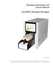
Operating Instructions For The<br />
X-Seal AAS<br />
Automated Adhesive Sealer<br />
__________________________________<br />
Version 1 Release 1 November 2009<br />
©<strong>FluidX</strong> Ltd.<br />
<strong>FluidX</strong> Ltd. Monks Heath Hall, Chelford Road, Nether Alderley, Cheshire, SK10 4SY, UK.<br />
T: +44(0) 1625 861 614 F: +44(0) 1625 861 615 E: info@fluidx.co.uk www.fluidx.co.uk<br />
Page 1 of 35<br />
Operating Instructions For Automated Adhesive Sealer
This document is for information only; the manufacturer accepts no liability for errors<br />
contained herein or for incidental or consequential damages with the furnishing,<br />
performance, or use of this material.<br />
Unless otherwise specified references to names or parts is purely casual and has the purpose<br />
of illustrating the product. The contents of this publication may not be reproduced in any<br />
form or by any means (including electronic storage and retrieval or translation into a foreign<br />
language) without prior agreement and written consent from the copyright owner.<br />
The information contained in this document is subject to change without notice.<br />
Page 2 of 35<br />
Operating Instructions For Automated Adhesive Sealer
TABLE OF CONTENTS<br />
1. INTRODUCTION 4<br />
2. DIRECTIONS FOR USE 5<br />
3. HEALTH AND SAFETY 6<br />
4. CONNECTING AIR SUPPLY 9<br />
5. CONNECTING VOLTAGE SUPPLY 10<br />
6. SWITCHING ON THE SYSTEM 11<br />
7. FOIL OR FILM LOADING 12<br />
8. PLATE SUPPORTS 15<br />
9. INTERCHANGING THE ROLLER AND PRESSURE CONTROL 16<br />
10. FOIL / FILM POSITION & LENGTH 17<br />
11. OPERATION PROCEDURE AND OPTIMISATION 18<br />
12. FURTHER INFORMATION 21<br />
13. RECOMENDED SEALS 22<br />
14. COMMUNICATION PROTOCOL 23<br />
15. COMMANDS 27<br />
16. CLEANING 28<br />
17. SPECIFICATIONS 29<br />
18. MAINTENANCE 30<br />
19. FAULT FINDING 34<br />
20. DECLARATION OF CONFORMITY 35<br />
Page 3 of 35<br />
Operating Instructions For Automated Adhesive Sealer
1. INTRODUCTION<br />
For your own personal safety please read this manual before operating the Automated<br />
Adhesive Sealer.<br />
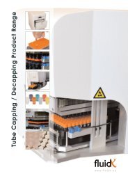
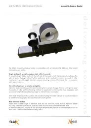
The X-SEAL AAS System has been designed for robotic integration, offers a fast effective<br />
solution for the cold roll sealing of microlitre plates for experimentation, storage or<br />
transportation.<br />
Cold plate sealing is rapidly becoming the new process for the effective sealing of 96, 384<br />
and 1536 plates. The extensive range of sealing materials now available for our new<br />
instrument give permanent or peelable high integrity seals for all plate material types. The<br />
range includes ultra clear materials for colorimetric or fluorimetric assays, along with solvent<br />
resistant seals with low temperature (-80°C) storage characteristics.<br />
The new X-SEAL AAS has been designed for bench top mounting with clean lines, easy<br />
access and operation. It features a serial port allowing RS232 communication for robotic<br />
control plus a touch screen for manual operation. Seal process time and pressure is fully<br />
adjustable with visual indication for operation fault and ‘low foil’ warning.<br />
X-SEAL AAS can be as easily integrated into robotic platforms from all leading automation<br />
companies.<br />
Manufactured for:<br />
fluidX Ltd.<br />
Monks Heath Hall<br />
Helford Road<br />
Nether Alderley<br />
Cheshire<br />
SK10 4SY<br />
UK<br />
Manufactured by:<br />
KBiosystems<br />
5 to 10 Paycocke Close<br />
Paycocke Road<br />
Basildon<br />
Essex<br />
SS14 3HS<br />
UK<br />
Tel: +44 (0) 1625 861 614<br />
Fax: +44 (0) 1625 861 615<br />
Email: sales@fluidx.co.uk<br />
www.fluidx.co.uk<br />
Page 4 of 35<br />
Operating Instructions For Automated Adhesive Sealer
2. DIRECTIONS FOR USE<br />
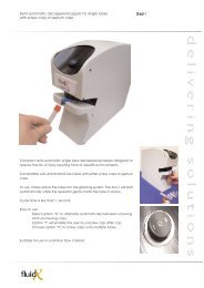
The unsealed plate is placed on a shuttle, which extends from the front of the sealer, allowing<br />
full access with a robotic arm. The shuttle is drawn into the unit automatically and the plate<br />
can be sealed in 12 seconds, depending on the plate, foil and roller pressures selected. The<br />
shuttle then slides the sealed plate out, presenting the plate back to its original position.<br />
The sealer, as part of a fully automated plate handling system, which can be controlled via a<br />
PC using a RS232 communication protocol, Alternatively the X-SEAL AAS can be manually<br />
operated as a stand alone unit using the built–in touch screen display.<br />
Each roll of cold roll sealing foil/film is supplied with a backing sheet and is sufficient for appox<br />
two thousand five hundred plates. The transfer platen cuts the foil to cover the entire plate<br />
surface but does not permit any overhang down the side, which would affect the plates<br />
handling, or the visibility of barcodes.<br />
The foil can be trimmed to fit the exact length of the plate, or have a ‘tab’ to assist with foil<br />
removal, when required. The rolls of sealing foil/film are either aluminium or clear laminates<br />
and are able to produce permanent, pierceable or peelable seals with Polypropylene,<br />
Polystyrene or Polythene Microwell plates.<br />
To keep the size and weight to a minimum, the unit uses clear and dry compressed air and all<br />
parameters, such as time and pressure are fully adjustable to ensure a perfect, even seal with<br />
different plate and film formats.<br />
User safety has been carefully considered during the design process, to eliminate risk of<br />
contact with moving parts of the internal mechanism during operation.<br />
Page 5 of 35<br />
Operating Instructions For Automated Adhesive Sealer
3. HEALTH AND SAFETY<br />
It is Important that the X-SEAL AAS is installed and operated in such a way that<br />
all applicable Heath and Safety requirements are met. It is the user’s<br />
responsibility to ensure that all relevant Health and Safety Regulations are<br />
identified and complied with. Failure to do so, may result in damage to the<br />
equipment and could cause personal injury.<br />
In particular, the user should study the contents of this guide carefully before<br />
handling or operating this equipment.<br />
Under no circumstances will the supplier of this equipment be liable for any<br />
incidental, consequential or any special damages of any kind whatsoever,<br />
including but not limited to lost profits arising from, or in anyway connected<br />
with the use of this equipment or this instruction manual.<br />
Warnings<br />
Do not operate this instrument in an atmosphere containing explosive gases.<br />
Only approved, supplied mains cord must be used with this instrument. If an extension<br />
lead is required, the lead MUST be earthed.<br />
Safety guards MUST be used at ALL times during the operation of the unit.<br />
Always remove the sealing film before transporting the sealer.<br />
The unit should only be used in a suitably ventilated area. The use of solvents on the<br />
unit is not recommended.<br />
Certain components become hot during the correct operation of the equipment.<br />
These are marked as below. Due care should be taken to avoid personal injury.<br />
Disconnect air supply and electrical supply before removing safety guards.<br />
Warning symbols<br />
Risk of electric shock.<br />
!<br />
Moving equipment.<br />
Earth protective conductor.<br />
Page 6 of 35<br />
Operating Instructions For Automated Adhesive Sealer
Operating conditions<br />
Temperature Range:<br />
Relative Humidity:<br />
Voltage:<br />
Operating 15º C to 40º C<br />
Storage 0º C to 40º C<br />
Operating 10% to 80% Non-condensing<br />
Storage 10% to 80% Non-condensing<br />
The Automated Thermal Sealer is supplied for direct connection<br />
to normal 115VAC or 240VAC supply, with a variation of 108VAC<br />
to 250VAC.<br />
The following fuses are fitted to the Automated Thermal Sealer:<br />
Supply Fuses Fitted in Plug Fuses Fitted in Sealer<br />
230VAC 13 Ampere T5AH 250V<br />
115VAC No Fuses T5AH 250V<br />
Only refit the correct type of fuse. Must be IEC127 approved for use in EC Countries.<br />
Must be C.S.A. or UL listed or recognised for use in Canada or the United States of America.<br />
Operate the Automated Thermal Sealer in a draught-free environment to help maintain<br />
temperature stability. The time between cycles may increase if sealing plate cools.<br />
Place the unit on a secure bench to avoid movement during use. Allow 170mm at the front of<br />
the instrument for operation of the plate carrier.<br />
The X-SEAL AAS should be only operated in an environment with a temperature range of 15°C<br />
- 40°C and a non-condensing relative humidity range of 10% - 80% . The unit should be kept<br />
out of draughts and air currents as they will have an adverse effect on the temperature<br />
stability of the sealing platen.<br />
The machine should be mounted on a sturdy bench to avoid any bounce during operation.<br />
When locating the machine there should enough space allowed for the shuttle to extend<br />
without hitting anything or anybody. The reduced weight makes the X-SEAL AAS much easier<br />
to move into a suitable position.<br />
Page 7 of 35<br />
Operating Instructions For Automated Adhesive Sealer
Operating conditions<br />
Shown below is the main control PCB showing the fuse position and layout.<br />
All fuses used upon this unit are T rated (Time lag) and H (High Breaking Capacity)<br />
1 Amp Fuse<br />
Page 8 of 35<br />
Operating Instructions For Automated Adhesive Sealer
4. CONNECTING AIR SUPPLY<br />
All electrical and pneumatic connections are made to the lower rear of the unit (Fig. 6). This is<br />
the only point of interconnection.<br />
UK Europe and Asia supplied units.<br />
The unit is supplied with a 6mm push-in connector to fit into the 1/4 BSP inlet.<br />
USA supplied units.<br />
The unit is supplied with a 1/4 inch push-in connector to fit into the Filter Regulator input.<br />
When fitting an air connector to the Automated Thermal sealer prevent the bulkhead fitting<br />
from turning while tightening the connector to prevent loosening.<br />
Air supply should be 80psi (5.5 bar) / 87psi (6 bar) max.<br />
Provide 50 litres/minute through a pressure regulator as there is no air regulation of the air<br />
within the instrument.<br />
NOTE<br />
Exceeding the maximum pressure may damage the unit. The air supplied must be clean, dry<br />
and oil-free. Most air regulators include a water filter but not an oil filter; this may need to be<br />
fitted separately.<br />
Fig. 6<br />
The air supply for the X-SEAL AAS should be 80psi ( 5.5 bar ) and a maximum of 87psi ( 6 bar ).<br />
The supply should be able to provide 50 litres/minute through a pressure regulator as there is<br />
no regulation of the air within the X-SEAL AAS. Exceeding the maximum pressure may<br />
damage the unit. The air supplied must be clean, dry and oil-free. Most air regulators include<br />
a water filter but not an oil filter; this may need to be fitted separately.<br />
Page 9 of 35<br />
Operating Instructions For Automated Adhesive Sealer
5. CONNECTING VOLTAGE SUPPLY<br />
The Automated Thermal Sealer utilizes a standard IEC inlet, which is fused and switched.<br />
Plug the IEC lead in the inlet and switch on the rocker I.O. switch (Fig. 7). The display mounted<br />
on the front of the unit should illuminate.<br />
NOTE<br />
The system is self regulated to sense voltage differences between 100 and 240 VAC.<br />
Fig. 7<br />
NOTE:<br />
If the X-SEAL AAS. Fails to power up when correctly connected, then check the external fuse<br />
at the rear of the machine – see above photo. If this fuse has failed then a replacement 5A<br />
anti-surge fuse is included with machine. If this fuse is intact then an internal fuse may have<br />
failed. Either contact ABgene ® or your distributor before removing the main cover. The photo<br />
above shows the location of the fuse that may have blown. It is a 1A anti-surge fuse and 2<br />
replacements are provided with the machine.<br />
Also check that the E-Stop is in its operational position i.e. fully out.<br />
Page 10 of 35<br />
Operating Instructions For Automated Adhesive Sealer
6. SWITCHING ON THE SYSTEM<br />
When the power is successfully connected to the<br />
sealer, the touch screen display will light up and the<br />
display will be as Display 1.<br />
Display 1<br />
The unit will sound three times whilst the system<br />
starts and the display will change to as shown in<br />
Display 2.<br />
Display 2<br />
The next screen then waits for the proceed area of<br />
the screen to be touched.<br />
Display 3<br />
After proceed has been touched, the initialising<br />
screen is displayed and remains until the shuttle<br />
homes into the sealer and returns to the preset plate<br />
loading position.<br />
Display 4<br />
Page 11 of 35<br />
Operating Instructions For Automated Adhesive Sealer
The next screen gives the option to proceed with<br />
the sealing action or go into the set up choice<br />
area. The correct plate length and number of rolls<br />
can be checked to that displayed. Ensure that the<br />
correct plate and carrier are loaded onto the<br />
shuttle prior to sealing. The set up will take into the<br />
multi-choice screen to select the option required.<br />
Display 4<br />
7. FOIL OR FILM LOADING<br />
To load the foil/film. When starting from new, or after using the reel for some time, the low film<br />
alarm will indicate that a new foil or film reel needs to be loaded.<br />
When this alarm is displayed during use, it indicates that the foil or film roll has only a certain<br />
number of seals left available from the loaded roll. The number of seals left after the alarm<br />
appears is variable through the position of the foil sensor and normally factory set to that<br />
stated in the original specification.<br />
The next screen is displayed whilst the sealer sets<br />
itself to the foil loading condition. This requires that<br />
the cutter is raised clear of the foil area and that all<br />
moving parts are homed.<br />
Display<br />
6<br />
Display 7<br />
Once this screen is displayed, the sealer must then<br />
be switched off prior to the foil/film reel being<br />
loaded. The display will then go blank and the air<br />
will be vented and isolated.<br />
See later parts of this chapter 8 for details on how to<br />
load the foil/film<br />
Display 8<br />
After the procedure for loading the foil/film has<br />
been completed and the doors all closed with<br />
power and air reapplied, the sealer can then be<br />
switched back on. The start-up displays all appear<br />
as already defined, and then display 8 waits for<br />
confirmation that the service door has been<br />
opened and the foil off cut removed. The service<br />
door opening will cause the air to be evacuated,<br />
this will be restored once the door is closed and<br />
locked shut. Display 5 is then shown ready to<br />
continue.<br />
Display 9<br />
Page 12 of 35<br />
Operating Instructions For Automated Adhesive Sealer
Always ensure that sufficient room is made around the side cover area to permit easy access<br />
for loading the foil, installing the blank foil backing spool and for threading the foil through the<br />
guide rollers and into the cutter.<br />
The mains and air supply must be connected to load the foil. The screen offers a foil load<br />
option to ensure that the internal mechanism is moved to the default locations. The cutter is<br />
powered to the up position, ready for the foil loading. When the side cover is removed the<br />
interlock mechanism immediately exhausts all of the air within the instrument and allows the<br />
foil to be placed through the open punch/die and foil clamp assembly, to allow the film and<br />
backing to be threaded through the system.<br />
Both foil and backing spindles that contain the roll of film are fitted with manually adjustable<br />
clutch mechanisms.<br />
The side cover is removed by first undoing the two retaining knobs and the side cover can<br />
then be carefully removed outwards. This action will immediately cause the internal air supply<br />
to be cut off - an air discharge will be heard and this is normal.<br />
Care should be taken with the side cover since the control interlock mechanism on the side<br />
cover is now exposed and could cause injury or damage. The two fixing knobs should also be<br />
safely stowed for later reuse after foil loading is complete.<br />
A diagram is located on the side of the unit detailing the path of the foil and backing film.<br />
The top spindle holds the full or part full reels of foil or film. This is loaded onto the spool that fits<br />
the top spindle. This spool has a smaller spindle hole (18mm) and the red spool-locking ring<br />
has a left hand thread. After clamping the foil securely and fitting to the top spindle, taking<br />
care to have the foil fitted onto the spool he right way round – see diagram for rotation<br />
direction, the white inner washer (18mm bore), the spring, the outer metal washer (18mm<br />
bore) and the knurled clutch adjusting nut (18mm LH) should be screwed half way onto this<br />
shaft (LH).<br />
An empty reel core should then be firmly fitted to the second spool. This spool has a 20mm<br />
bore and 20mm clutch components and should be fitted to the lower spindle, similar to the<br />
procedure for the top spool. The knurled nut should then be screwed on to about half way<br />
(RH).<br />
The foil end and backing should then be unfastened and passed under the central fixed<br />
guide roller and towards the cutter area, but over the horizontal flat platen. The backing<br />
Page 13 of 35<br />
Operating Instructions For Automated Adhesive Sealer
should then be peeled away from the foil or film and passed down between the rounded<br />
end of the platen and the rear of the cutter<br />
block. As the backing is pulled down and around the lower fixed spool, the foil or film should<br />
be fed through and over the open cutter block.<br />
Extreme care should be exercised when in the cutter area since sharp surfaces are present<br />
and accessible. The cutter itself is retracted 100mm above the cutter block and since the air<br />
has been evacuated and isolated, the cutter can only slowly lower through gravity and so<br />
should impose no real risk other than keeping clear of the very sharp edges.<br />
After feeding the foil or film through the cutter, the backing can be then pulled around the<br />
lower fixed guide and onto the empty reel core already fitted to the lower bobbin. This will<br />
need to be secured centrally to the core using sticky tape. See the diagram printed on the<br />
side of the X-SEAL AAS. for the exact foil and backing route and direction.<br />
Once the backing has been secured and several turns made to start the reel off, the side<br />
cover can be refitted, taking care with the protruding interlock mechanism, place the cover<br />
on towards the main cover and located the interlock peg into the hole. After ensuring that<br />
the peg is located properly and that the fixing studs have passed through the side cover, the<br />
knobs can then be refitted. Over tightening of these knobs is not necessary.<br />
The screen prompt should then be touched to start the final stage. This will permit the air back<br />
into the system and lower the cutter to trim off the excess foil or film that has been previously<br />
fed through the cutter whilst loading.<br />
The front access door should now be carefully opened and lowered. This action will again<br />
operate the safety system and evacuate the air from the X-SEAL AAS. Again this is normal.<br />
Access to the off cut of the foil or film can then be gained to the right of the doorway. After<br />
extracting the foil off cut, the door must be securely closed to continue. The internal air supply<br />
will then be reconnected.<br />
The final step is to make sure that the tension for both spools has been correctly set and that<br />
the foil or film is feeding correctly. To ensure that the foil or film is presently correctly to the<br />
transfer suction head, it is necessary to have the cut end of the foil or film tacked onto the<br />
pads located under the cutter. The spool is then driven backwards by a motor and gearbox,<br />
which gives the tension to present the foil or film flat and in line for the transfer suction head.<br />
Too much tension (anti-clockwise) will break the hold at the tacked cut end-too little<br />
(clockwise) and the foil will sag over he platen and so give no assistance to the suction<br />
pickup. This could lead to either transfer failure or a wrinkled plate seal.<br />
The lower spool is also driven but in the opposite direction to the top spool. This assists with<br />
keeping the foil flat over the platen. The tension of the lower spool should be adjusted to take<br />
up the surplus backing discharged from the end of the platen. Too much tension (clockwise)<br />
will cause the foil or film to be pulled down over the cutter end of the platen, too little tension<br />
(anti-clockwise) will prevent the lower spool from keeping pace with the backing discarded<br />
and could result in the backing being pulled through the cutter. This will put undue stress on<br />
the cutter block and should be avoided. Please note that the spool tension adjustments are<br />
opposite to each other.<br />
After becoming familiar with the foil or film installation procedure, the system can be quickly<br />
loaded and operational, particularly if the same foil or film is being reloaded since the settings<br />
already established may not need adjusting, as it is not necessary to remove the bobbins to<br />
reload a new reel. Part used reels as well as full reels can be loaded onto the top bobbin.<br />
However, care should be taken in loading non-empty cores to the lower bobbin since over<br />
capacity will be detrimental to the clutch mechanism and the backing could become<br />
unguided onto the bobbin. This could cause the backing to foul with other moving parts<br />
within the X-SEAL AAS and cause plate sealing failure.<br />
Page 14 of 35<br />
Operating Instructions For Automated Adhesive Sealer
8. PLATE SUPPORTS<br />
Plate supports are found in the spares kit provided and support the under side of the plate to<br />
ensure that the seal is even across all the wells of the plate.<br />
To select the correct plate support, measure the underside of the wells to the bottom skirt and<br />
select a support which is slightly larger.<br />
Page 15 of 35<br />
Operating Instructions For Automated Adhesive Sealer
9. INTERCHANGING THE ROLLER AND PRESSURE CONTROL<br />
The roller is located immediately behind the service door, located at the front of the<br />
instrument. When the main door is carefully lowered and laid flat, the roller and fixings can<br />
easily be seen and accessed. This will cause the interlock to exhaust the system air and isolate<br />
the incoming air supply until the door is closed.<br />
The roller assembly can be removed by undoing the three fixings with the supplied Allen key.<br />
The yoke assembly can then be rotated through 90 degrees and lowered through the shuttle<br />
opening.<br />
The procedure to replace the roller is as above, taking care not to damage the roller and<br />
that the yoke assembly is rotated in the correct direction to locate the yoke upper surface<br />
with its mating part, attached to the cylinders. Prior to fitting ensure that the correct roller has<br />
been selected and that the roller is free to rotate on its spindle. The locking screws at the rear<br />
of the yoke should also be checked for tightness, since access to these is reduced once the<br />
yoke assembly has been installed.<br />
To achieve the correct sealing for different plates and foils or films, the X-SEAL AAS<br />
incorporates a manual adjustable pressure regulator and analogue gauge with a range of 0-<br />
4Bar (0-0.4Mpa). The pressure is initially set for about 1 bar and should suit most sealing<br />
applications.<br />
During operation, the gauge displays the pressure set for the roller. The roller pressure is<br />
adjusted through a precision control located above the pressure gauge. These are both<br />
secured into the main frame of the X-SEAL AAS and can be accessed only when the side<br />
cover is removed. During operation, the gauge can be seen to operate during the rolling<br />
operation. This pressure is manually adjusted using the knob. Rotating the knob clockwise (+)<br />
will increase the pressure whilst rotating anti-clockwise will reduce the pressure (-). One full<br />
turn of the knob is approximately equal to 1 Bar (14.5 PSI or 0.1 MPa), so by careful rotation,<br />
the desired pressure can easily be assessed and set. The units are normally despatched with<br />
the pressure set to 1 Bar.<br />
As described above, to adjust the pressure it is necessary to remove the foil side cover.<br />
Rotating and removing the two side facing knobs do this, will then permit the cover to be<br />
carefully moved SIDEWAYS, to permit the safety interlock mechanism to disengage from the<br />
main frame assembly. This will cause the interlock to exhaust the system air and isolate the<br />
incoming air supply until the door is closed.<br />
Adjustments in the pressure required for each set-up for variations in plate type, foil type and<br />
roller type will quickly become familiar with use and often permit the correct set up to be set<br />
at the first attempt. As with changing foils and having to adjust the spindle clutch pressures,<br />
the more the operators become familiar with the instrument, the resulting set-up time will<br />
become quicker.<br />
To aid in roller selection, the different types have been colour coded. Each former for the<br />
roller will be coloured to quickly identify the type of roller and its hardness.<br />
A full reference chart will be found in the specification chapter within this manual.<br />
Page 16 of 35<br />
Operating Instructions For Automated Adhesive Sealer
10. FOIL / FILM POSITION & LENGTH<br />
There is some limited adjustment available that can alter the position of the foil on the plate<br />
and of the length of the cut foil. The fore and aft adjustment of the foil can be used to vary<br />
the amount of overhang of the foil at the back an front of the plate. The side to side<br />
adjustment can be used to place the foil so that the numbers on the plate are visible. The foil<br />
length can be adjusted from a minimum to suit robotic piercing to a maximum to provide a<br />
tab for peeling.<br />
The adjustment of all these parameters is very similar in that the position stops that must be<br />
adjusted are all of the same type. These stops have a threaded body that is M10 with a pitch<br />
of 1mm so that one full turn of the stop will result in a change in position of 1mm. All of the<br />
adjustments require the cover to be removed.<br />
10.1 Foil length<br />
The foil length is set at 125mm initially and may be adjusted to increase this by a maximum of<br />
5mm each end. This standard factory setting of 125mm cannot be reduced; doing so may<br />
cause the foil vacuum cups to become uncovered. To create a tab at the front of the plate<br />
the stop at the rear of the fore and aft transfer must be adjusted and the same to create a<br />
tab at the rear of the plate, the stop at the front of this transfer is to be adjusted.<br />
Note: All adjusted positions are to be checked with cutter in the down position to ensure<br />
against crashes<br />
10.2 Side to side placement<br />
The foil placement position may be changed by up to 5mm on each of the plate. To move<br />
the foil further to the left, adjustments are to be made the left hand stop located on the top<br />
of the transfer unit. The same is for moving the foil further to the right adjust the right hand<br />
stop.<br />
Page 17 of 35<br />
Operating Instructions For Automated Adhesive Sealer
11. OPERATION PROCEDURE AND OPTIMISATION<br />
The X-SEAL AAS System has been designed to reliably seal plates of different heights and<br />
different plastics, using a variety of foils and films, to give a seal with varying properties. These<br />
components will require different sealing conditions.<br />
The quality and strength of the seal created between the sealing films will vary with different<br />
conditions. In general, increasing either the sealing pressure or duration of seal, gives a<br />
stronger, more complete seal. However over-sealing on a regular basis is not recommended,<br />
as applying more pressure can cause damage to the plate being sealed. This in turn, would<br />
reduce the number of times a particular plate can be resealed. Therefore a balance has to<br />
be achieved, that gives an acceptable seal with the minimal plate damage or distortion.<br />
Another optimisation factor to be taken into account is the surface area of the plate.<br />
A plate with thin raised rims around each tube (chimney), will have a reduced surface area,<br />
compared to a flat plate or with wide raised rims. This would mean that less pressure is<br />
needed to seal the thin rim plate in comparison to the wide rim. The pressure that the roller<br />
exerts during sealing is fully adjustable, as is the speed of travel for the shuttle.<br />
From the set up on screen display 5, the choice<br />
menu is displayed as shown on display 6. Selecting<br />
the roll set up option will then display screen 10. This<br />
allows for the pre-measured plate length to be set.<br />
Pressing enter will then move onto the next screen.<br />
Display 10<br />
This next screen permits the number of foil/film rolls<br />
to be set. Pressing enter will then move onto the<br />
next screen.<br />
Display 11<br />
This next screen permits the exact position for the<br />
shuttle out location. This sets the range of 235 to 275<br />
units. Pressing enter will then move onto the next<br />
screen.<br />
Display 12<br />
Page 18 of 35<br />
Operating Instructions For Automated Adhesive Sealer
This next screen permits the choice for half or full<br />
rolling. If yes is toggled, then the rolling procedure is<br />
to roll from the centre of the plate to the back, raise<br />
the roller and move back to the centre and then<br />
roll from this position to the front. The roller then<br />
stays down and the shuttle and plate move forward<br />
so completing a final full length roll. Toggling for no<br />
on the display eliminates the final full roll. Pressing<br />
enter will then move onto the next screen.<br />
Display 13<br />
There is a facility to operate the machine remotely.<br />
This screen permits the option to be selected by<br />
toggling yes or no. Selecting yes will activate the RS<br />
232 connector at the rear of the unit. Pressing enter<br />
will then move onto screen 16 if the remote option<br />
is not selected.<br />
Display 14<br />
If the RS232 option is selected, then screen display<br />
15 becomes active. This allows for the RS232 option<br />
to be de-selected by selecting the set up option on<br />
this screen. This will then revert back to screen<br />
display 14 where the no option can be toggled.<br />
Again, pressing the enter area will move onto<br />
screen display 16.<br />
Display 15<br />
The roll speed for the plate sealing is adjustable to<br />
cater for the requirements of different rollers, plates<br />
and foils/films. The adjustable range of 1 to 50<br />
permits for the slow rolling requirements of some<br />
films, typically crystallography which is set at<br />
around 10, but this is normally set at 50 for fast<br />
rolling. Pressing enter will then move onto the next<br />
screen.<br />
Display 16<br />
To permit curing time for some foil/film glues after<br />
they have been cut, a delay is selectable from 0 to<br />
5 seconds to allow the exposed glue at the cut<br />
edges to air dry and become less tacky. This<br />
prevents any possibility of wrinkles being formed<br />
during the plate sealing operation. Pressing enter<br />
will then go back to screen display 6.<br />
Display 17<br />
Page 19 of 35<br />
Operating Instructions For Automated Adhesive Sealer
This screen is displayed as shown in display 18. This is<br />
similar to screen display 5, but defines that the<br />
sealing operation has commenced and is always<br />
displayed after screen 5.<br />
Display 18<br />
11.2 Commands, Indications and warnings.<br />
The X-Seal System is software controlled, employing micro-controllers. All commands,<br />
indications and warnings are affected via the touch sensitive LCD Display Panel located on<br />
the front of the unit. The user-friendly menu regulates all operations. The Sequence of events is<br />
as follows:-<br />
11.3 Initiating Unit Operation.<br />
Loading the machine with foil and triming the foil is described under section 8. The display is<br />
used to set the sequence.<br />
11.4 Foil low sensor<br />
There is a sensor mounted below the spindle to provide a warning that the foil is running low.<br />
As supplied the sensor is in the centre position of five possible positions. It may be adjusted up<br />
or down to increase or decrease the amount of foil remaining when the warning is given.<br />
11.5 Cover removal<br />
All power and air connections must be removed prior to the removal of the cover. Should it<br />
become necessary to remove the cover it is secured by three screws on one side and by two<br />
on the other side. The small side cover over the foil roll also needs to be removed. To lift the<br />
cover the foil spindles need not be removed or the clutch loosened as the cover can slide<br />
behind the bobbins. The shuttle and service door are not part of the cover. These are<br />
attached to the base unit. Once the cover has been lifted up so that it is clear of the power<br />
and air inlet the ribbon cable connecting the display to the circuit board is revealed. This<br />
must be disconnected before the cover can be removed completely. The cover should be<br />
lifted at the back to ease it over the front of the machine. Replacing it is the reverse of<br />
removal.<br />
11.6 Internal fuse failure<br />
If a voltage outside of the 100 to 240VAC is applied to the unit then the internal fuse will fail.<br />
This is a 5A type F fuse and is installed into the built in fuse holder as part of the mains inlet<br />
panel. This can be clearly seen in the adjacent inlet panel assembly pictures.<br />
Page 20 of 35<br />
Operating Instructions For Automated Adhesive Sealer
12. FURTHER INFORMATION<br />
The amount of times a microplate can be sealed and resealed can be increased by<br />
using the minimal amount of temperature and seal time to prevent chimney damage.<br />
Sealed microplates that have been stored in a fridge or freezer do not always have to<br />
be brought back to room temperature before peeling e.g. <strong>FluidX</strong> EZ Peel, a peelable<br />
heat seal for polypropylene plates. (See the complete <strong>FluidX</strong> range for more<br />
information).<br />
<strong>FluidX</strong> has not yet tested seals from alternative suppliers and therefore is unable to<br />
make recommendations regarding their usage at this time.<br />
To prevent the risk of cross-contamination between wells when removing a peelable<br />
seal, consider using one that can be pierced. Centrifuging before removal may also<br />
be beneficial.<br />
Page 21 of 35<br />
Operating Instructions For Automated Adhesive Sealer
13. RECOMENDED SEALS<br />
Heat Seal Rolls<br />
40-1001 Adhesive "Gold" Aluminium Sealing Foil (peeling). Good solvent<br />
resistance, Temp range; minus 80°C to 120°C. 100m per roll (approx. 800<br />
plates) for use with Xcs-384<br />
40-1002 Adhesive Aluminium Sealing Foil (piercing). Good solvent resistance,<br />
Temp range; minus 80°C to 120°C. 100m per roll (approx. 800 plates) for<br />
use with Xcs-384<br />
40-1003 Adhesive Polyolefin film (peeling). Micro-encapsulated solvent. Temp<br />
range; minus 25°C to 120°C.100m per roll (approx. 800 plates) for use with<br />
Xcs-384<br />
40-1004 Adhesive Polyolefin film, pre-pierced for good gas exchange, Temp<br />
range; minus 25°C to 120°C. 100m per roll (approx. 800 plates) for use with<br />
Xcs-384<br />
40-1005 Adhesive gas permeable membrane, impervious to fluids but provides<br />
good gas exchange. 100m per roll (approx. 800 plates) for use with Xcs-<br />
384. (81mm width, requires 45-1100 adapter)<br />
40-1006 Adhesive Polypropylene film (peeling). High solvent resistance. Temp<br />
range minus 80°C to 120°C. 100m per roll (approx. 800 plates) for use with<br />
Xcs-384<br />
40-1007 Adhesive Cristal Clear Polypropylene film (peeling). Solvent resistant.<br />
Temp range minus 40°C to 120°C. 100m per roll (approx. 800 plates) for<br />
use with Xcs-384<br />
40-1008 Adhesive PCR Film Roll (AB-2558) (100m) on 80mm backing, for use on<br />
Abgene format sealer and XCS-384 (81mm width, requires 45-1100 kit).<br />
40-1009 Adhesive PCR Foil Roll (AB-2626) (200m), Abgene format sealer<br />
40-1010 Black PE Sealing foil, Peeling, light tight, good biological and solvent<br />
resistance, Temperature range: -40°C to +60°C, for use with Xcs-384<br />
40-1011 Adhesive silicone foil, Piercable, high solvent resistance. Ideal for sealing<br />
plates containing DMSO. 150M per roll, to seal approximately 1200 plates.<br />
(81mm width, requires 45-1100 adapter)<br />
40-1012 Adhesive silicone foil, Peelable, high solvent resistance. Ideal for sealing<br />
plates containing DMSO. 150M per roll, to seal approximately 1200 plates.<br />
(81mm width, requires 45-1100 adapter)<br />
43-1032 QPCR adhesive clear seals (AB-1170), Optically clear for QPCR and other<br />
fluorescence applications, (500m x 115.5mm), Peelable seal for PP and PS<br />
plates, Velocity 11 format (41-1004 Equivalent)<br />
43-2032 QPCR adhesive clear seals (AB-1170), Sample Roll (25m), Optically clear<br />
for QPCR and other fluorescence applications, (25m x 115.5mm),<br />
Peelable seal for PP and PS plates, Velocity 11 format (41-1004 Equivalent)<br />
Page 22 of 35<br />
Operating Instructions For Automated Adhesive Sealer
14. COMMUNICATION PROTOCOL<br />
Introduction<br />
The 9 pin D type at the rear of the unit is labelled RS232 and is for connecting the X-Seal to a<br />
PC using a serial port. The PC then uses the protocol detailed in section 13 to communicate<br />
with the X-Seal This allows the sealing parameters to be programmed from the PC; enabling<br />
the PC to request status information from the X-Seal; provides low foil and other warnings to<br />
the PC.<br />
Serial Port Set-up<br />
9600---Baud rate<br />
8 Data bits<br />
No parity<br />
1 Stop bit<br />
No handshaking<br />
All communications via Ascii.<br />
Cable<br />
PC (9 way female)<br />
SEAL-IT 100 (9 way female)<br />
Pin 2<br />
Pin 3<br />
Pin 5<br />
Pin 2<br />
Pin 3<br />
Pin 5<br />
Message Response time<br />
The unit responds to each message within 100 Millisecond.<br />
Configuring for remote operation<br />
On the touchscreen use the advanced menu to set the following:<br />
When the system is powered up the operator is prompted to clear the plate load area before<br />
the plate shuttle is extended.<br />
“Mode” to “Rmt”.<br />
This sets the unit into remote mode and ignores commands issued from the touch screen. This<br />
is strongly recommended when controlling the unit from a host computer. Once unit has been<br />
set to remote mode the unit must be restarted to allow remote control.<br />
Page 23 of 35<br />
Operating Instructions For Automated Adhesive Sealer
System Initialisation<br />
Once unit has been restarted it must be initialised via the PC<br />
PC sends<br />
I<br />
X-SEALreplies:<br />
ok<br />
Status Message<br />
PC sends<br />
?<br />
X-SEALreplies:<br />
<br />
The status byte is a hexadecimal value represented in Ascii, ie the<br />
characters "ff" means 0xff hex.<br />
bit values:<br />
bit 0<br />
bit 1<br />
bit 2<br />
bit 3<br />
bit 4<br />
bit 5<br />
bit 6<br />
Low Air<br />
error<br />
Sealing<br />
Low air during seal<br />
Not initialised<br />
Low foil<br />
Door open/side cover missing<br />
Begin Sealing Command<br />
PC sends<br />
S<br />
X-Seal replies<br />
ok<br />
if the sealing operation has commenced<br />
or<br />
err<br />
If it is unable to start the operation.<br />
Page 24 of 35<br />
Operating Instructions For Automated Adhesive Sealer
The seal it will not start sealing if the following conditions exist:<br />
bit 0<br />
bit 1<br />
bit 2<br />
bit 3<br />
bit 4<br />
bit 5<br />
bit 6<br />
low air<br />
error<br />
sealing<br />
low air during seal<br />
Not initialised<br />
low foil<br />
Door open/side cover missing<br />
Error Message<br />
PC sends<br />
E<br />
X-Seal replies<br />
##<br />
where ## is a decimal value represented in Ascii, ie the characters "01" means error 1.<br />
Modify Seal Parameters<br />
PC sends<br />
P%=###<br />
X-Seal replies:<br />
ok<br />
Note: Wait until unit is in idle state before modifying seal parameters.<br />
where % is the parameter number and ### is the parameter value.<br />
% is a single digit decimal number and ### is a 3 digit decimal number represented in Ascii<br />
e.g.<br />
The string P1= 127 plate length to 127mm<br />
The following parameters can be set<br />
Page 25 of 35<br />
Operating Instructions For Automated Adhesive Sealer
Parameter Description Units<br />
1 Plate length 124mm to 128mm<br />
2 Number of rolls 1 to 5<br />
3 Shuttle roll position 235mm to 275mm<br />
4 Full or half roll 0= Full roll 1= Half roll<br />
5 Not used<br />
6 Roll speed 1 to 50<br />
7 Not used<br />
8 Autosave 0=off 1=on<br />
Note:- 1 = Low speed<br />
50 = High speed<br />
Reading X-Seal parameters<br />
PC sends<br />
P%<br />
X-Seal replies:<br />
###<br />
where % is the parameter number and ### is the parameter value.<br />
% is a single digit decimal number and ### is a 3 digit decimal number represented in Ascii<br />
e.g.<br />
To read the current plate length, send the string<br />
P1<br />
The X-Seal replies with the string<br />
128<br />
if the plate length is 128mm.<br />
Manual Save Seal Parameters (Command R)<br />
Normally Seal parameters are written to eeprom so that they can be saved through unit<br />
power down. In some applications it may be necessary to turn autosave off (P8 = 0). This is<br />
because the action of writing to eeprom may cause occasional corruption of<br />
communications messages. If autosave is disabled then it is possible to save the sealing<br />
parameters through power down using the R command.<br />
Page 26 of 35<br />
Operating Instructions For Automated Adhesive Sealer
15. COMMANDS<br />
E Error status<br />
T<br />
Trim<br />
O<br />
Open door<br />
L<br />
Lock<br />
S<br />
Seal<br />
I<br />
Initialise<br />
R<br />
Save Seal Parameters<br />
P1=128<br />
Set plate length in mm<br />
P2=2<br />
Set no of rolls<br />
P3=256<br />
Set load position<br />
P4=1<br />
Set roll type (0 = Full roll, 1 = Half roll)<br />
P5<br />
Not used<br />
P6=30 Set roll speed to 30<br />
P7=2<br />
Set cure delay to 2 seconds (1-5 seconds)<br />
P8=0<br />
Set auto save of parameters on or off<br />
P1<br />
? q<br />
Query plate length, similar for all other p variables<br />
Query status<br />
This will return an 8 bit hex number in ascii format.<br />
Bit values:-<br />
bit 0<br />
bit 1<br />
bit 2<br />
bit 3<br />
bit 4<br />
bit 5<br />
bit 6<br />
bit 7<br />
Low Air<br />
error<br />
Sealing<br />
Low air during seal<br />
Not initialised<br />
Low foil<br />
Door open or side cover missing<br />
Not used<br />
Page 27 of 35<br />
Operating Instructions For Automated Adhesive Sealer
16. CLEANING<br />
!<br />
Before using any cleaning or decontamination method, other than that<br />
recommended by the manufacturer, users should check with the<br />
manufacturer that the proposed method will not damage the unit.<br />
!<br />
In case of radioactive spillage's, Advanced Biotechnologies Limited,<br />
recommend that you use a proprietary cleaning agent and follow the<br />
manufacturers instructions.<br />
You may clean the X-Seal cover, with a cloth dipped in water or<br />
ethanol, methanol or formaldehyde may also be used.<br />
!<br />
THE UNIT SHOULD NOT BE<br />
IMMERSED IN SOLVENTS<br />
!<br />
DO NOT USE ACETONE OR<br />
ABRASIVE CLEANERS.<br />
Before using any cleaning or decontamination method, other than that recommended by<br />
the manufacturer, users should check with the manufacturer that the proposed method will<br />
not damage the unit.<br />
Always remove the power and pneumatic supplies before cleaning the unit.<br />
Do not turn on power and pneumatic supplies until the unit is fully dry.<br />
DO NOT USE ACETONE OR ABRASIVE CLEANERS<br />
Page 28 of 35<br />
Operating Instructions For Automated Adhesive Sealer
17. SPECIFICATIONS<br />
Power Supply: Minimum 100VAC 50/60Hz<br />
Maximum 240V AC 50/60Hz<br />
Power Consumption:<br />
Fuse Rating:<br />
150 Watts Nominal<br />
5 Amp anti-surge<br />
Dimensions: 370 x 433 x 594mm (W x H x D)<br />
Weight:<br />
Air Input:<br />
Air Requirement:<br />
Air Input Pressure:<br />
Minimum Operating Pressure:<br />
Minimum Operating<br />
Ambient Temperature:<br />
Maximum Working<br />
Temperature Ambient:<br />
Minimum Sealing<br />
Plate Height:<br />
Maximum Sealing<br />
Plate Height:<br />
Protection:<br />
28Kg<br />
6mm or 1 /4 “ BSP Female Thread<br />
50 Litres per minute<br />
5.5 Bar (80 PSI)<br />
5.5 Bar (80 PSI)<br />
15 0 C<br />
40 o C<br />
8mm<br />
50mm<br />
IP20<br />
Fire Retardancy: Plastic Case & Trays ECCEN 6073<br />
Cycle Time Minimum:<br />
Access Panels Interlocked<br />
30 Seconds (Sealing Time Adjustable)<br />
Main cover, Side Cover & Service Door<br />
Page 29 of 35<br />
Operating Instructions For Automated Adhesive Sealer
18. MAINTENANCE<br />
Lubricating and cleaning the cutter<br />
The punch and die used in the SEAL-IT 100 system needs regular lubrication to maintain the<br />
quality of the cut of the sheets. Approximately every 2500 cuts (which is approximately after<br />
every full roll or if the unit has not been operated for more than 7 days, the following<br />
procedure should be carried out.<br />
1. Set the system for as if it were in foil or film reel loading mode. This will raise the cutter<br />
for easier access.<br />
2. Remove the side cover. This will automatically evacuate the air within the system and<br />
internally isolate the incoming air supply. Leave the mains voltage on.<br />
Please ensure that all parts removed during maintenance are kept safe<br />
3. Apply a small quantity of the lubricating grease provided using a spatula or finger to<br />
the rear of the heels of the die.<br />
Page 30 of 35<br />
Operating Instructions For Automated Adhesive Sealer
Rear View<br />
4. Open the service door.<br />
Page 31 of 35<br />
Operating Instructions For Automated Adhesive Sealer
6. Apply a small quantity of the lubricating grease provided using a spatula or finger to<br />
the front of the heels of the die.<br />
7. Close and secure the service door.<br />
Page 32 of 35<br />
Operating Instructions For Automated Adhesive Sealer
8. Replace the side panel and secure with the two knobs, Ensuring that safety plunger is<br />
place correctly<br />
9. Press ‘continue’ on the touch screen to resume normal operation.<br />
20.1 CLEANING THE CUTTER<br />
The procedure stated above should be used as a safety guide when cleaning the cutter, this<br />
should be carried out if unit states to produce poor cutting.<br />
20.2 CLEANING THE SHUTTLE RAILS<br />
Wipe the shuttle rails with a clean dry cloth and apply a small amount of lubricating grease<br />
along the full length of both rails.<br />
Page 33 of 35<br />
Operating Instructions For Automated Adhesive Sealer
19. FAULT FINDING<br />
THIS EQUIPMENT SHOULD ONLY BE DISMANTLED BY PROPERLY TRAINED PERSONNEL. REMOVING<br />
THE MAIN COVER EXPOSES POTENTIALLY LETHAL MAINS VOLTAGES.<br />
The X-Seal Automated Adhesive Sealer has been designed to give long term reliability with<br />
the minimum of maintenance.<br />
Annual maintenance is recommended to maintain instrument integrity and optimal<br />
performance.<br />
Should a problem occur with the sealing, an initial inspection of the component may identify<br />
cause and necessary action required.<br />
21.1. ERROR CODES<br />
Error 2 Shuttle failed to reach the HOME switch<br />
Error 4 Low air glitch- Air loss during cycle<br />
Error 6 Failed to reach foil transfer REAR switch<br />
Error 7 Failed to reach foil transfer FRONT switch<br />
Error 8 Failed to reach foil transfer R-H switch<br />
Error 9 Failed to reach foil pick UP switch<br />
Error 10 Failed to reach foil pick DOWN switch<br />
Error 11 Failed to reach cutter UP switch<br />
Error 12 Failed to reach foil transfer L-H switch<br />
Error 13 Failed to reach roller UP position<br />
Error 14 Door open<br />
Page 34 of 35<br />
Operating Instructions For Automated Adhesive Sealer
20. DECLARATION OF CONFORMITY<br />
As detailed under the European Machinery Directive 89/392/EEC (amended by 91/368/EEC)<br />
and under the UK legislation. The supply of Machinery (Safety) Regulations 1992 (SI<br />
1992/3073).<br />
As detailed under The Electromagnetic Compatibility Directive 89/336/EEC (amended by<br />
91/263/EEC and 92/31/EEC and the UK legislation, the Electromagnetic Compatibility<br />
Regulations 1992.<br />
As detailed under The European Low Voltage Directive 73/23/EEC (amended by 93/68/EEC)<br />
and the UK legislation, The Electrical Equipment (Safety) Regulations 1994<br />
The Declaration of Conformity is provided for the following equipment:-<br />
Equipment<br />
Automated Adhesive Sealer<br />
The X-Seal AAS has been type tested by- Intertek Testing Services and issued report No.<br />
EM02007020 and EM02007020 to the following EMC Standards:<br />
BS EN 55-022 Class A<br />
BS EN 50-082-2<br />
Emission<br />
Immunity<br />
Transposed Harmonised Standards<br />
BSEN 12100-1 Safety machines: Concepts General: principles for design; basic terminology &<br />
methodology<br />
BSEN 12100-2 Safety of machines: basic concepts, general principles for design; technical<br />
principles<br />
BSEN 61010 Safety requirements for electrical Equipment for measurement, control &<br />
laboratory use<br />
BSEN 60204 safety of Machinery; electrical equipment of machines (section 19)<br />
BSEN 50081-2 Electromagnetic Compatibility; generic emission standard, industrial<br />
environment<br />
BSEN 61000-6-2 Electromagnetic compatibility (EMC) Generic standard, immunity for<br />
industrial environments<br />
Other Standards<br />
BS5378 safety signs & colours<br />
Name & Address of the Responsible Person within the EU<br />
I declare that as the Authorised representative, that the above information in relation to the<br />
supply/manufacture of this product, is in conformity with the stated standards and other<br />
related documents, following the provisions of (89/392/EEC)<br />
Alan A E Shepherd<br />
Units 5 to 10 Paycocke Close<br />
Basildon<br />
Essex<br />
SS14 3HS<br />
United Kingdom<br />
Page 35 of 35<br />
Operating Instructions For Automated Adhesive Sealer