XPP-721 Personal Pipettor GUI Software Operation Manual - FluidX
XPP-721 Personal Pipettor GUI Software Operation Manual - FluidX
XPP-721 Personal Pipettor GUI Software Operation Manual - FluidX

Create successful ePaper yourself
Turn your PDF publications into a flip-book with our unique Google optimized e-Paper software.
NoticesThe information contained in this manual is subject to change without notice.Apricot Designs, Inc assumes no responsibility for any damage or loss resultingfrom the use of this manual.2
Table of ContentsPage1. <strong>Operation</strong> Overview 32. System Requirements 43. <strong>Software</strong> Installation 44. Program Initialization 55. Main Screen Overview 66. Modes of <strong>Operation</strong> 87. Editing Plates 108. Creating Protocols 159. Editing Protocols 3410. Running Protocols 3511. Set Parameters 3612. Interface Menu 3813. Interface Tool bar 4114. Appendix A: Pump Setup 423
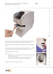
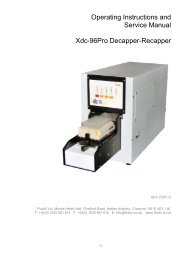
1. <strong>Operation</strong> OverviewTurn On <strong>Pipettor</strong> & PumpStart NMS <strong>GUI</strong>To Simulation ModeOpen Existing FileInit <strong>Pipettor</strong>To <strong>Operation</strong> ModeSelect HeadMenu-> Tools->Retrieve Plate DB(PP->PC)Edit PlateNoPlateExistsSelect PlatesNoPlateExistsImport Plate databasefrom <strong>Pipettor</strong> (optional)Plates ExistMove Plates to StationsWriteProtocolExecutionSave Protocol4
2. System Requirementshigher)a. Hardware requirements1. CPU: Intel Pentium III minimum (AMD CPU should be equal or2. Memory: 64M minimum (recommend 128M or Higher)3. Hard Drive: 100M free space minimum4. CDROM Drive: 8x speed or higher5. Monitor: 1024x768 or higher resolution6. Two Buttons Mouse7. Sound Card optional8. One serial port minimum.b. <strong>Software</strong> requirements1. MS Windows 2000 with Service Pack 42. MS Windows XP with Service Pack 23. MS Windows 2003 Server3. <strong>Software</strong> Installation1) Place the installation CD in the CD-ROM. The <strong>GUI</strong> software could beautomatically installed, then follow step 5). If you install it manually,follow step 2):2) Go to your CD ROM drive under My Computer3) Double click setup.exe file or NMS<strong>GUI</strong>.msi File4) If there is no MS DOTNET framework 2.0 in your computer, theDOTNET framework 2.0 will be installed automatically in a few minutes.5) Follow the installation wizard.6) Click Close to finish installation.Go to Start Programs Apricot Designs Inc and select NMS to run the software.5
4. Program InitializationWhen the ADI program is running, it automatically detects the pipettor model,connects, and enters the corresponding main interface:‣ When the pipettor is turned on and connected successfully, initialization of thepipettor (Homing tasks for the Plungers and the XYZ of the shuttle) will takeplace, and the software will be in <strong>Operation</strong> Mode. <strong>Operation</strong> Mode is for thecontrol of all actual functions and movements of the pipettor. A physicalconnection between the pipettor and the computer is required for using<strong>Operation</strong> Mode.‣ When the pipettor is not powered, is not connected to the computer or has notconnected successfully, the software will enter Simulation Mode. The mainpurpose of Simulation Mode is for users to create protocols for all models ofApricot pipettor, without having a pipettor connected the computer. It is alsoa useful tool for training purposes.‣ To switch between <strong>Operation</strong> Mode and Simulation Mode, simply select(reset pipettor) from the tool bar of the <strong>GUI</strong> Main Screen. A Reset <strong>GUI</strong>window will appear, click Simulation Mode and select a instrument modelfrom the list, then click Next to enter Simulation mode. To enter <strong>Operation</strong>Mode select “Real Execution Mode” and click Next (<strong>Operation</strong> Mode willonly be activated when a pipettor is connected to the computer successfully)initialization will take place, and control of pipettor will become active.6
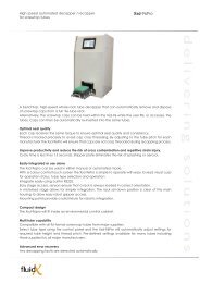
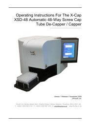
5. Main Screen Overview4 5 6 71 {2 {3 {89{{1011 13 14 15127
1. Title bar - Shows new file or the existing file path and file name.2. Menu – Handle files, set variables, transfer plate database and manual modes.3. Tool bar - Icons for functions that are frequently used.4. Processing – Shows the progress of the running protocol by percentage completion.5. Tip Volume Bar – Shows actual liquid volume in the pipettor tips and any remainingvolume.6. Loop Cycle - Shows running protocol loop cycle and inner loop cycles remainingwhen a protocol is executed.7. Current Plate Assignment – Shows current plate and spacer information on eachplate station. The orientation of stations in the frame matches the actual stations of the<strong>Pipettor</strong>.8. Tab SelectionProtocol – show protocol.Head – select appropriate head.Plate – show plate inventory and edit plates for plate databaseConfig – change instrument parameters.Admin – login in as Administrator to view or change special instrumentparameters.9. Status – Shows pipettor model, communication port, selected pipettor head,<strong>Operation</strong>/ Simulation Mode and the dynamic information of the pipettor in action.10. Display Window – Shows protocol or other displays of the tab selected.11. Command Button Group – Shows the commands to edit or execute protocol.12. Set Loop Cycle – Sets the number of loop cycles to run a selected protocol.13. Parameter Name – Shows all parameters for a protocol function.14. Parameter Value – Shows all parameter values and allows editing of parametervalues.15. Parameter Unit – Shows the unit of the corresponding parameter.8
6. Modes of <strong>Operation</strong>6.1 Confirm Instrument Model• In <strong>Operation</strong> Mode, the computer retrieves the pipettor information, i.e. modeland the original position automatically. The pipettor model name will be shown inthe first panel of status bar.• In Simulation Mode, to change the instrument model, click (reset pipettor)from the tool bar or select Reset <strong>Pipettor</strong> under <strong>Manual</strong> Mode menu; the Reset<strong>GUI</strong> window will be displayed; select an instrument model and click Next; theplate layout corresponding to the selected model will now be displayed in themain interface.For NMS instruments, the models available in Simulation Mode are: MS384-6D(125),MS96-6D (550), MS96-6H (550) and MS96-6S (105)9
6.2 Select Pipetting HeadSelect an appropriate pipetting head to begin a protocol.1. Click the Head tab and the Head Inventory window will be displayed.2. To change the pipetting head for a different model, click Change Head,the Change Button now becomes Lock Head, after you take out the oldhead and put the new head into the head assembly, click the Lock Headbutton, the pipettor will finish loading head automatically.3. Select head Type for either Fixed or Disposable Tips, Volume range and number ofChannels, the corresponding picture of the head will be displayed.4. Select the appropriate head from the list according to channel, volume pertip, and product number of the pipetting head.Note: It is critical to match the product number on the physical head with the selectionlisted in the database. Wrong selection may cause damage to the pipettor and labware.5. As an Administrator, you can set and save the Self Define parameters ifnecessary. Select a head from the head list, input two volume values todivide into three volume ranges and set different calibration value for eachrange, also could define the maximum volume for the selected head, thenclick Save. To restore the original value for calibration value or themaximum volume, click the Default button nearby.1
7. Editing Plates7.1 Creating a PlateIf the plate inventory is empty, you will have to add plates by physically teaching themon the pipettor. Right click on the plate station on which you want to teach the newplate, and select Add New Plate from the drop-down list. A Plate Training window willbe displayed.Follow the steps to teach a new plate, during the process, if the head crashes with theplate, click Home Z-Axis button to return the head to its original position.Step1 Assign a name in the Define Plate Name space, then click Next.Step2 Select a plate type from the Define Plate Type list and place a plate of the sametype on the assigned station, then click Next.Step3 Define Well Centre – Use Jog Up, Down, Left, Right, Forward, Backward to1
align the tips to the centre and top of the wells as shown in the diagram, then click Next.When teaching a 384 plate with a 96 head or a 1536 plate with a 384 head, align thetips in the first quadrant of the wells (the top left quadrant – A1). When teaching a 384plate with a single row head of 96-channel configuration, align the tips with Row A andthe left quadrant (A1) – with the plate on the plate station, this should be the well on theleft of the short side of the plate closest to the user. When teaching a plate with a singlecolumn head, align the tips with the wells in column 1 (on the short side of the plateclosest to the user in front of the instrument) and at the left quadrant for an offset head.The Define X Y Original Point button is available in operation mode. Thisfunction is used for saving the newly defined position as the default XY starting valuewhen defining a new plate. This is useful when the initial alignment between the tipsand the well centre is a long way out at the start of teaching a plate. Click on DefineX Y Original Point to save settings before clicking Next button.Step 4 Define Tip Touch – Again, use Jog Right or Left until the tips touch the side ofthe well slightly, then click Next.Step 5 Define the Bottom of the wells – Jog Down until the tips touch the bottom of theplate slightly, then click Next.Step 6 Define Passing Height – Jog Up until the tips reach a safe height to pass abovethe plate when the instrument moves, then click Finish to complete the process.7.2 Edit PlateIf the head or the instrument is changed, the definitions of the plates should be checked andedited where necessary to ensure they are properly calibrated for the safe and accurateoperation of the instrument. Right click on a plate station populated with a plate you want toedit and select Edit Old Plate, the Training Plate window will be displayed. Follow steps 3to step 6 in 7.1 above to complete the plate editing.7.3 Copy PlateTo use an existing plate as a template and copy it, click the Plate tab in the main window, theplate inventory will be displayed. Right click on the plate to be used as a template and select1
Copy, then type in a new name for this plate, the copied new will be added into the plateinventory.7.4 Rename PlateRight click on the plate picture in the plate inventory and select Rename, then type in a newname.7.5 Delete PlateRight click on the plate in the plate inventory and select Delete, after confirming deletion, theplate will be permanently removed from the plate inventory. You cannot delete a plate that is1
eing used in the main window. If you delete all plates in the plate database, then you mustadd new plates to the database before use.7.6 Populating the Plate DeckBefore creating a protocol, the plate stations on plate deck must be populated with the platesto be used. The orientation of the plate deck in the main window matches the actual stationsof the <strong>Pipettor</strong>.Populating plate stationsMethod One:1. Right click on an empty station or click on Plate tab. The Plate Inventory will bedisplayed.2. Left click on a plate and drag-and-drop the plate icon onto the station.3. If the same plate is to be used on other stations, simply left click on the empty station/s toadd the plate.Method Two:1. Right click on an empty station or click Plate tab. The Plate Inventory will be displayed.2. Left click on an item in Plate Inventory3. Left click on an empty station4. Yon can continue to use this plate to populate other empty stations by left-clicking on theempty stations.Removing plates from a station:Method One: Either double click on the plate picture on the station or right click on the platepicture and select Remove The Plate from the drop-down list.Method Two: If replacing one type of plate with a different type, drag-and-drop the new platefrom the Plate Inventory onto the existing one.1
7.7 Place SpacersUsually, if the heights of plates on the stations are similar, you do not need to put spacersbelow. Spacer is used when an irregular plate height is presented on station, i.e. one deepwell plate and the rest are shallow well plates. When selecting spacers in <strong>GUI</strong>, physicalspacers are needed under the plate. Adding a spacer will also reduce the shuttle traveldistance in “Z” direction. Each spacer height is 13mm, a maximum of three spacers isavailable for selection, and the number of spacer plate is represented in number times “X”on spacer icon. Add spacer to selected plate on station accordingly, and the number times“X” will display at the right top corner in the plate picture on that station.Note: Consult Apricot Designs for spacer part numbers.To access Spacer: Click on Spacer tabTo add Spacer: Right click on an empty station, a spacer list pops up, select an itemTo delete Spacer: Double clicks on the item for that station in Spacer window1
8. Creating ProtocolsAfter populating the Plate deck with plates and adding any necessary spacers,a protocol can be created from the Plate window. Right click on a populatedplate station in Plate tab, a drop-down function menu will appear, then leftclick to select a highlighted function to create a protocol command on thatstation.8.1 Functions for operationThere are 10 basic functions on the drop-down function menu: Aspirate, Dispense,Empty, Mix, Wash, Pause, Comment, Transfer, Define XYZ Speed & Set Loop.When using a head with a single row or single column of tips, one more function for RowSerial Dilution or Column Serial Dilution will be displayed.1
The NMS instrument also has an additional function – Reformat, incorporating 4in1 and1To4.‣ When using a 96 or 96 offset head, put four 96-well plates on stations 1, 2, 3,and 4, one 384-well plate on station 5, and a wash station in position 6(recommended). When the Reformat command is selected there are twochoices, 4in1 or 1to4. 4in1 allows the transfer of liquid from four 96-wellplates into one 384-well plate, and 1To4 transfers liquid from one 384-wellplate into four 96-well plates.‣ When using 384 head, place four 384-well plates on stations 1, 2, 3, and 4,one 1536-well plate on station 5, and a wash station in position 6(recommended). The 4in1 command will transfer liquid from four 384-wellplates into one 1536-well plate, and 1To4 will transfer liquid from one 1536-well plate into four 384-well plates.1
8.2 Edit ParameterWhen creating a new protocol line, all the parameters with the default values for thisprotocol line will be displayed in the parameter window. To change a parameter value,click on the parameter value (to the right of the parameter description). Use the displayedicons to select an appropriate value. Numeric values may also be changed from thekeyboard.1
1) AspirateClick on the Aspirate command line in the protocol to show the Aspirate parameters.The first line shows the function name.o Station: The default station is that was clicked on to create the command line forthe protocol, the station can be changed the by clicking on the Station value, a listof all the available stations with plates is displayed and a different station may beselected.2
o Airgap and Volume: Select the appropriate row to change the value for Airgapand liquid Volume by using the pop-up number pad or type in the numbers usingthe keyboard.o Pre-Airgap allows an airgap to be aspirated before aspirating the liquid and Post-Airgap aspirates an airgap after aspirating liquid.Tips: Always use an Air Gap if possible. However, avoid using a large volume that couldcause bubbles to form at the bottom of wells when dispensing.If variables have been set for volume by menu->Settings->Set Variable (seesection 12.2), to use a variable to set the value for the Volume or Airgap, rightclick the parameter value and select the relevant variable from the drop-down list.2
o Plunger Speed: Drag the plunger speed slider on the pop-up slider bar to increaseor decrease Plunger Speed or type in numbers by keyboard.If variables have been set for speed by menu->Settings->Set Variable (seesection 12.2), to use variables for the value for the Speed, right click the valueand select the variable from the pop-up list of all the speed variables.o Quadrant: When a 384 well plate is used with a 96 head, a 1536 well plate isused with a 384 head or an appropriate single column/row head is used, the tipswill align with the first Quadrant as default. Change the default Quadrant byselecting the desired quadrant on the pop-up component.2
o Depth: Drag the tip depth slider to set the Start Depth of tips in the wells of theplate on the pop-up depth slider bar or type in the numbers by keyboard. If the tipdepth slider position is not changed, the default depth is 50% (halfway into thewells).If variables have been set for depth by menu->Settings->Set Variable (seesection 12.2), to use variables for the value of the Depth, right click the value andselect the variable from the pop-up list.For incremental aspiration operation, change the Divided Steps value to begreater than 1 by select the step number from the pop-up step list or type in the2
number by keyboard. For incremental aspiration an End Depth must be selectedthat is equal to or lower than the Start Depth. The <strong>Pipettor</strong> will aspirate step bystep from the Start Depth until reaching the End Depth.o Side Tip Touch: If you want to set side tip touch for aspiration, select the valueof Side Tip Touch and select L (left touch), R (right touch), F (front touch) or B(back touch) on the pop-up menu. The Side Tip Touch Depth must also be set.o Single Column: When a single column 8CH, 8Offset or 16CH pipetting head isused, column Aspiration can be executed. Select a column from the pop-up menu.A tool tip text displays the column number when cursor moves that helps user toselect a column.2
o Single Row: When a single row 12CH, 12Offset or 24CH pipetting head is used,row Aspiration can be executed. Select a row from the pop-up menu. A tool tiptext displays the row letter when cursor moves that helps user to select row.o Note: The user can input text (such as liquid name) in the note text box.2
2) DispenseClick the Dispense command line in the protocol to edit Dispense parameters.o Input the dispense Volume.o Drag the Plunger Speed slider to increase or decrease Plunger Speed.o Select Quadrant if applicable.o Set Start Depth by moving slider.o For incremental step dispense operation, input a value greater than 1 for theDivided Steps parameter, select an End Depth equal to or higher than the StartDepth. The <strong>Pipettor</strong> will dispense step by step until reaching the End Depth.2
o For dispensing small volumes of liquid, the Side Tip Touch and Bottom TipTouch functions may be used. Select True or False in the pop-up list for bottomtip touch.o Single column or row Dispense can be done when a single column or rowpipetting head is used. Select Single Column or Single Row in the pop-up menu.3) MixSelect the Mix command line in the protocol to edit Mix parameters.o Input the mix Volume (always with an Airgap if possible) and Retained Volumeif necessary.o Drag the Plunger Speed slider to increase or decrease Plunger Speed.o Select Quadrant if applicable.o Set the number of mix Cycles using the pop-up list or type in a number.o For more thorough mixing, use the Mix At Corners function with 4 cyclemixing. The tips will be shifted to each of the corners of the plate and mixing willoccur.2
o Set the Aspirate Depth and Dispense Depth by moving the pop-up slider.o Set Side Tip Touch or Bottom Tip Touch and set the Touch Depth needed.o Single column or row Mixing can be done when a single column or row pipettinghead is used. Select Single Column or Single Row at the bottom of the window.4) EmptySelect the Empty command line in the protocol to edit Empty parameters.o Drag the Plunger Speed slider to increase or decrease Plunger Speed.o Select Quadrant if applicable.o Set Empty Depth by moving slider.o For emptying a small amount of liquid, the Side Tip Touch and Bottom TipTouch function may be useful.o Single column or row Empty can be done when a single column or row pipettinghead is used. Select Single Column or Single Row at the bottom of the window.5) WashSelect the Wash command line in the protocol to edit Wash parameters.2
o Input the wash Volume required (always use an Airgap if possible).o Drag the slider to increase or decrease Aspirate Plunger Speed and DispensePlunger Speed.o Set the number of wash Cycles by selecting or typing in a number.o To wash at different depths, set Mix Aspirate Depth and Mix Dispense Depthby moving the pop-up slider bar.o Using Pump is only for washing on station 6, select True in the pop-up list, andmake sure the pump is connected and switched on.6) PauseSelect the Pause command line in the protocol to edit Pause parameters.The pipettor will be paused according to the selection.o For a timed pause, set pause values for Minutes and Seconds by using the pop-upnumber pad or typing in numbers. The pipettor will resume its motion once theselected time has elapsed.2
o When “Wait for User” is set to True, the pipettor will pause until the resume keyis pressed by the user. The pipetting head can be changed during the pause ifTrue is set for Change Head. The <strong>Pipettor</strong> will lock the new head and resumemotion once the resume key is pressed.7) CommentSelect the Comment command line in the protocol to edit Comment parameters.Input the required text in the pop-up text box, the message will display in the protocolline. This can be useful for making remarks or organising a long protocol.8) TransferTransfer is a convenient command that combines the Aspirate and Empty operations inone command. Select the Transfer command line in the protocol to edit Transferparameters.3
o A target station is selected in the function sub menu when crating a transferprotocol, the Source Station and Target Station may be changed in theparameters later.o Input the transfer Volume (always include Pre-Airgap or Post-Airgap ifpossible).o Drag the Plunger Speed sliders to increase or decrease Aspirate and DispensePlunger Speed.o Select Source Quadrant and Target Quadrant if applicable.o Set Aspirate Depth and Dispense Depth by moving slider.o For small volume dispenses, use of the Side Tip Touch and Bottom Tip Touchfunctions recommended.o Single column or row transfer can be executed when a pipetting head with singlecolumn or row is used. Select Source Single Column or Row and Target SingleColumn or Row.9) Column Serial Dilution3
When selecting the 8ch or 16ch head, the Column Serial Dilution menu will bedisplayed.Select the Column Serial Dilution command line in the protocol to edit its parameters.o Input the required Airgap and aspirate Volume from the Source plate.o Drag the Plunger Speed slider to set Source and Target Plunger Speed.o Select Source Quadrant and Target Quadrant if applicable.o Set Source Aspirate Depth by moving slider.o Set Source Single Column and Define Target Start Column to Target EndColumn.o Input Mix Volume and number of Cycles, and set Mix Aspirate and DispenseDepth from destination.10) Row Serial DilutionWhen selecting the 12ch or 24ch head, the Row Serial Dilution menu will be displayed.Click the Row Serial Dilution command line in the protocol to edit its parameters.3
o Input the Airgap and aspirate Volume from the Source plate.o Drag the Plunger Speed slider to set Source and Target Plunger Speed.o Select Source Quadrant and Target Quadrant if applicable.o Set Source Aspirate Depth by moving slider.o Set Source Single Row and Define Target Start Row to Target End Row.o Input Mix Volume and number of Cycles, and set Mix Aspirate and DispenseDepth from destination.11) Reformat 4in1Reformat 4in1 transfers liquid from four plates into one plate and combines transfer andwash functions four times into one reformat operation. Select the Reformat 4in1command line in the protocol to edit its parameters.3
The Source Stations for aspiration are fixed on Stations 1,2,3,4 for 96 plates or 384plates, the Target Station for dispensing is fixed on Station 5 for 384 plates or 1536plates, and the Wash Station for washing tips between each transfer action is also fixedon Station 6 for a 96 wash plate or 384 wash plate.o Input Airgap and aspirate Volume from Source plate.o Drag the Plunger Speed slider to set Aspirate and Dispense Plunger Speed.o Set Aspirate Depth and Dispense Depth by moving slider.o For small volume dispensing, use of the Side Tip Touch and Bottom Tip Touchfunctions are recommended.o Input Volume, Plunger Speed, Cycle, Depth and Using Pump for washfunction.12) Reformat 1to4Reformat 1to4 transfers liquid from one plate into four plates and combines transfer andwash functions four times into one reformat operation. Click the Reformat 1to4command line in the protocol to edit its parameters.3
The Source Station for aspiration is on fixed Station 5 for 384 plates or 1536 plates, theTarget Stations for dispensing are fixed on Stations 1,2,3,4 for 96 plates or 384 plates,and the Wash Station for washing tips between each transfer action is also fixed onStation 6 for a 96 wash plate or 384 wash plate. 4in1 or 1to4 Reformat may also be donewithout a wash plate on station 6 if washing is not requiredo Input Airgap and aspirate Volume from Source plate.o Drag the Plunger Speed slider to set Aspirate and Dispense Plunger Speed.o Set Aspirate Depth and Dispense Depth by moving slider.o For small volume dispensing, use of the Side Tip Touch and Bottom Tip Touchfunctions are recommended.o To prevent tip contamination between each transfer, set “True” for Change Tips,pipettor will pause for changing pipetting head and continue action once resumekey is pressed.13) Define XYZ SpeedThe Define XYZ Speed function can modify X, Y or Z shuttle speed individually withina protocol if necessary, all commands in the protocol following the speed modification3
will run with modified shuttle speeds. To access the speed controls, click on a plate andselect Set Parameters. Select the individual speed parameters to edit the command linein the protocol . Drag the speed slider or type a number to set the X Axis Speed, Y AxisSpeed and Z Axis Speed.14) Set LoopFor protocols that consist of many repetitive functions, Set Loop (including Begin Loopand End Loop) can make protocols easier to manage and edit.To set up a loop within a protocol select Begin Loop to edit its parameters. Insert theBegin Loop command before the set of commands to be repeated. Enter a convenientname to identify the series of commands within the loop and set the number ofrepetitions. Insert the End Loop command after the last command in the loop.Input Loop Name, and click or type in a number for Loop Times. Use the Up & Downarrows on the Main Screen to move the Begin Loop command to the start of thecommands to be looped and move End Loop to where the loop should be ended.9. Editing Protocols3
There is a group of buttons for editing protocols in the centre part of the main screen.1). To Copy a line in a protocol – highlight the line to be copiedby left clicking on it in the protocol, then click the Copy button tocopy the line, the copied line will be added at the bottom of theprotocol. To copy a line into the middle of protocol, first click thetext Add and change into Insert in panel 6 of the status bar, thenselect a line and click Copy, a new line will added below thecopied line.2). To Delete a line in the protocol – highlight the line to bedeleted in the protocol and click the Delete button to remove thecommand line from the protocol.3). To Move a line up or down in the protocol – highlight the line to be moved, clickthe move up or down arrow to the desired location.4). To check (tick) the boxes of all lines of a protocol (i.e. so all commands will beexecuted) click on the All button.5). To Clear all lines i.e. uncheck all boxes to run command lines - click on thebutton Clear.A protocol may also be edited by right clicking on a command line of the protocol in themain screen, a drag-down menu for protocol editing will be displayed, select anappropriate function to achieve the same effect as the edit buttons.3
When editing a protocol by right-clicking a command, additional editing functions areavailable. The “Move To” function moves one command line from its original position toanother position in the protocol. Right click the line to be moved and select Move To.Right click on the command line under which the line to be moved is to be inserted. The“Move To” function in the menu will become “Move Here”. Select “Move Here”, theoriginal command line will now be inserted under the selected target line.o To Insert a new line between lines – In panel 6 of status bar, click text Add onceand it will turn into Insert. Click one line below which the new line should beinserted into, and create a new command that will be added below the selectedline.o To Edit a line in the Protocol window – highlight the line to be edited, thecommand parameters will then be displayed on the right-hand side of the screenand can now be edited.10. Run ProtocolThe Execution commands control the flow of protocol. The user may run the protocolcompletely automatically or run each line manually, stop a protocol, pause a protocoland choose the number of loop cycles for a protocol. There are two ways to run theprotocol, Run and Run Step.1). To run the entire protocol, click Run. If Run Check is set to true inConfig tab, a Confirm window will appear.It’s important to visually verify that the head and plates/Spacers matchwhat are actually in the Confirm window. Mismatching of the headand plates may cause serious damage. Head and Plate and Spacer (ifused) check boxes must be checked for the protocol to run.2). To run a single line of a protocol, highlight the line in the protocolwindow and click Run Step.3
o In the event that the tips are not empty (liquid remaining from a previous run),and Run is clicked, a message “Empty Tips First” will appear. Click button(Empty Tips) in the tool bar until the tips are empty. Then run protocol.Caution: If not select to empty tips in wash station, make sure a container isprepared to catch the liquid from the tips.o When the STOP button is clicked, a message is displayed, select Yes to terminateprogram, select No to continue running the program. The STOP button can alsobe used to pause a program. The program will be paused until No is selected inthe message window.o Several lines of a protocol may also be executed. Before running the protocol,check the boxes to the left of the commands to be executed. All checkedcommands will be executed but unchecked commands will not.o To run a protocol more than once, set the cycle times by using up/down arrow ortyping in a number before running the protocol or during the period to run theprotocol.11. Set Parameters1) Common ParametersSelect the Config tab on the display window to show the common parameters table.The left column shows the parameter name, the middle column shows the parametervalue (that can be edited), the right column shows the parameter unit and can alsorestore the default value for the parameter if clicked.3
2) <strong>Pipettor</strong> Communication PortIf the default communication port is not correct and the <strong>GUI</strong> could not enter operationmode, after the <strong>GUI</strong> enters simulation mode, select a COM port from the list and resetthe pipettor.3) Over ShootThe default over shoot value is 12uL for 550ul style pipetting head, 3uL for 125ulstyle pipetting head and 1uL for glass syringe head. Click the value for Over Shootand type in a number to edit if necessary.4) Shuttle SpeedThe travel speed of the shuttles (x,y,z motors) are available in three modes: Fast,Medium and Slow. The default speed is medium.5) Plunger Pause TimeAdjust plunger-waiting interval according the user’s requirement. Default is normal.6) Run CheckWhen the value is set True a Confirm window will be displayed before running aprotocol. It is used to prompt the user to make a visual check that the pipetting head,plates and spacers match the layout in the program.If the check box Test X,Y,Z Motions is checked, the protocol is run without plungeractions. It is helpful for check whether pipettor actions are satisfy your requirement andfor safety issue at the first time. It is also useful for detecting the appropriate tip depthposition before aspirate and dispensing the real liquor.4
2. Special ParametersThe special parameters can only changed when the user is logged in as an Administrator.Click the Admin tab in display window. An Administrator Login window will bedisplayed. Enter the user name “Apricot” and the password “2566088” to login in as anAdministrator, the special parameters window will be displayed. You can add a new userand change the password by clicking on the Administrator button. To avoid having toenter the password every time the Admin tab is selected, tick the check box Keep asAdministrator when re-entry.4
Shuttle Original X, YThe role to set shuttle original point is same as the Define X Y Original Point button inStep 3 for training a plate, you can enter X and Y position values here to let shuttle go tothe original point.Station Offset ValueThe setting configures the offset values for station under special requirements. Inputoffset values in one station. Be careful to give the correct station offset values to avoiddamage to the pipettor. The default values according to model are shown in the rightcolumn, click a value in the column to restore its default value.12. Interface Menu1) File‣ New - Open a new file to create a new protocol.‣ Open – Open an existing protocol file. Find file path and select an existingfile (files should be with .mp6 extension)‣ Save – Save changes to a protocol under the same file name. If it is a new file,give the file a new name (same as Save As operation.)‣ Save As – Save a new file or save a file to another file path. The file saves theedited protocol, selected instrument model, head, plates and spacers, andparameter settings for plunger pause, over shoot, and shuttle speed.‣ Print – Print current file that includes protocol, file name and time.‣ Close – Close the current protocol.‣ Exit – Exit the <strong>GUI</strong> software.2) Settings4
Set Variable – Variables can be set for Volume, Depth, and Speed. Select “SetVariables” from the Settings menu.Select Volume or Depth or Speed to set up variables individually. Thedefault names and values of the variables can be edited by the user. Thevariable lists are shown for selection when right clicking on a parameter valuefor volume, depth or speed in the edit command window of a protocol.3) Tools‣ Save Plate DB (PC-> PP) – Uploads the plate database from the computer tothe pipettor.‣ Retrieve Plate DB (PP -> PC) – Retrieves the plate database from thepipettor to a computer. This operation is used in two situations: 1) Whenthere is a problem with the plate database in the computer. 2) Transfer beingtrained plates from pipettor directly instead of training plate if first use orchange computer that without plate database to control the pipettor.4
4) <strong>Manual</strong> Mode‣ Reset <strong>Pipettor</strong> – Select to switch from <strong>Operation</strong> mode to Simulation mode,or reset pipettor from Simulation mode to <strong>Operation</strong> mode after thecommunication port is set correctly.‣ Initialize <strong>Pipettor</strong> – Select to initialize pipettor. When the pipettor is notfunctioning properly, initialize pipettor will send the shuttle back to X, Y andZ origin.‣ <strong>Pipettor</strong> Home X – Shuttle goes to the original position in X direction.‣ <strong>Pipettor</strong> Home Y – Shuttle goes to the original position in Y direction.‣ <strong>Pipettor</strong> Home Z – Head goes to the original position in Z direction.‣ Empty Tips – Select to empty the retained liquid in tips before running aprotocol. A message will be displayed, click Yes and pipettor will go to washstation to empty tips. If click No and pipettor will empty tips without moving,place a reservoir under the pipetting head to catch any liquid.5) Help‣ Basic Help – This manual is saved in the NMS-<strong>GUI</strong>-V.00.pdf file attachedwith the software setup package in the CD.‣ Version Record – Records the changes in different versions of the software.‣ About ADI…– Shows software and firmware version, and links to thewebsite and error report email address of Apricot Designs Inc.13. Interface Tool barThe tool bar includes some buttons for frequently used operations.Open a new file. The same as clicking New under File menu.Open an existing file. The same as clicking Open under File menu.Save a file. The same as clicking Save under File menu.Print a file. The same as clicking Print under File menu.4
Reset pipettor. The same as clicking Reset <strong>Pipettor</strong> under <strong>Manual</strong> Mode menu.Initialize pipettor. Click to initialize pipettor. The same as clicking Initialize<strong>Pipettor</strong> under <strong>Manual</strong> Mode menu.Shuttle Home X. The same as clicking <strong>Pipettor</strong> Home X under <strong>Manual</strong> Modemenu.Shuttle Home Y. The same as clicking <strong>Pipettor</strong> Home Y under <strong>Manual</strong> Modemenu.Head Home Z. The same as clicking <strong>Pipettor</strong> Home Z under <strong>Manual</strong> Modemenu.Empty tips. The same as clicking Empty Tips under <strong>Manual</strong> Mode menu.4
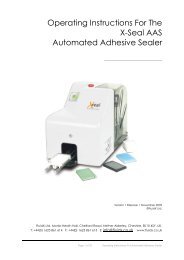
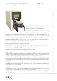
Appendix A – Pump SetupPipet Tip Wash Bath & PumpSetup Illustrations(For two pump head system)#17 #18Tubing 17 is thinner than tubing 18Tubing 18Channel Pipet tip Wash BathTubing AdaptorTubing 17PumpTubing 17Tubing 18Waste ContainerFresh Clean washwater fluidVersion 1.010/2002Page 14
Apricot Designs, Inc.825 S. Primrose Ave, Suite I, Monrovia CA 91016Tel: (626) 256-6088 Fax: (626) 256-6060info@apricotdesigns.comwww.apricotdesigns.com© Copyright 2006 Apricot Designs, Inc. (Version NMS – 1.00)4