4. INVERTER MULTI-SPLIT SYSTEM ROOM AIR-CONDITIONER ...
4. INVERTER MULTI-SPLIT SYSTEM ROOM AIR-CONDITIONER ...
4. INVERTER MULTI-SPLIT SYSTEM ROOM AIR-CONDITIONER ...

Create successful ePaper yourself
Turn your PDF publications into a flip-book with our unique Google optimized e-Paper software.
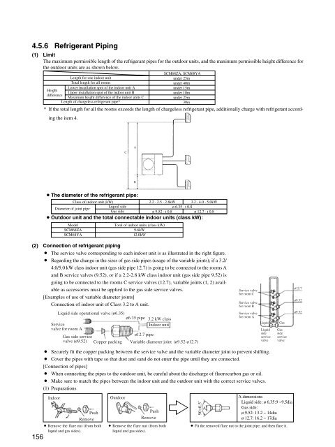
<strong>4.</strong>5.6 Refrigerant Piping<br />
(1) Limit<br />
The maximum permissible length of the refrigerant pipes for the outdoor units, and the maximum permissible height difference for<br />
the outdoor units are as shown below.<br />
Height<br />
difference<br />
Length for one indoor unit<br />
Total length for all rooms<br />
Lower installation spot of the indoor unit A<br />
Upper installation spot of the indoor unit B<br />
Maximum height difference of the indoor units C<br />
Length of chargeless refrigerant pipe*<br />
SCM68ZA, SCM68YA<br />
under 25m<br />
under 40m<br />
under 15m<br />
under 10m<br />
under 25m<br />
30m<br />
* If the total length for all the rooms exceeds the length of chargeless refrigerant pipe, additionally charge with refrigerant according<br />
the item <strong>4.</strong><br />
C<br />
A<br />
B<br />
¡The diameter of the refrigerant pipe:<br />
Class of indoor unit (kW)<br />
2.2 · 2.5 · 2.8kW 3.2 · <strong>4.</strong>0 · 5.0kW<br />
Liquid side<br />
Diameter of joint pipe<br />
ø 6.35 · t 0.8<br />
Gas side<br />
ø 9.52 · t 0.8<br />
ø 12.7 · t 0.8<br />
¡Outdoor unit and the total connectable indoor units (class kW):<br />
Model<br />
SCM68ZA<br />
SCM68YA<br />
Total of indoor units (class kW)<br />
9.6kW<br />
12.0kW<br />
(2) Connection of refrigerant piping<br />
¡ The service valve corresponding to each indoor unit is as illustrated in the right figure.<br />
¡ Regarding the change in the sizes of gas side pipes (usage of the variable joints); if a 3.2/<br />
<strong>4.</strong>0/5.0 kW class indoor unit (gas side pipe 12.7) is going to be connected to the rooms A<br />
and B service valves (9.52), or if a 2.2-2.8 kW class indoor unit (gas side pipe 9.52) is<br />
going to be connected to the rooms C service valves (12.7), variable joints (1, 2) available<br />
as accessories must be applied to the gas side service valves.<br />
[Examples of use of variable diameter joints]<br />
Connection of indoor unit of Class 3.2 to A unit.<br />
Liquid side operational valve (ø6.35)<br />
ø6.35 pipe 3.2 kW class<br />
Service<br />
valve for room A<br />
Indoor unit<br />
Gas side service<br />
valve (ø9.52) Copper packing<br />
ø12.7 pipe<br />
Variable diameter joint (ø9.52-ø12.7)<br />
Service valve<br />
for room C<br />
Service valve<br />
for room B<br />
Service valve<br />
for room A<br />
Liquid<br />
Liquid<br />
side<br />
service<br />
valve<br />
Gas<br />
Gas<br />
side<br />
service<br />
valve<br />
ø12.7<br />
ø9.52<br />
ø9.52<br />
156<br />
¡ Securely fit the copper packing between the service valve and the variable diameter joint to prevent shifting.<br />
¡ Cover the pipes with tape so that dust and sand do not enter the pipe until they are connected.<br />
[Connection of pipes]<br />
¡ When connecting the pipes to the outdoor unit, be careful about the discharge of fluorocarbon gas or oil.<br />
¡ Make sure to match the pipes between the indoor unit and the outdoor unit with the correct service valves.<br />
(1) Preparations<br />
Indoor<br />
Push<br />
Remove<br />
¡ Remove the flare nut (from both<br />
liquid and gas sides).<br />
Outdoor<br />
Push<br />
Remove<br />
¡ Remove the flare nut (from both<br />
liquid and gas sides).<br />
90+0.5˚<br />
A<br />
A dimensions<br />
Liquid side: ø 6.35:9 ~9.5dia<br />
Gas side:<br />
ø 9.52: 13.2 ~ 14dia<br />
ø 12.7: 16.2 ~ 17dia<br />
¡ Fit the removed flare nut to the joint pipe, and then flare it.