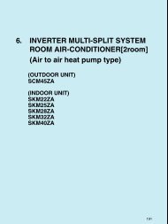
4. INVERTER MULTI-SPLIT SYSTEM ROOM AIR-CONDITIONER ...
4. INVERTER MULTI-SPLIT SYSTEM ROOM AIR-CONDITIONER ...
4. INVERTER MULTI-SPLIT SYSTEM ROOM AIR-CONDITIONER ...

You also want an ePaper? Increase the reach of your titles
YUMPU automatically turns print PDFs into web optimized ePapers that Google loves.
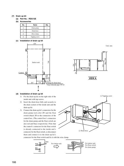
(7) Drain up kit<br />
(a) Part No. : RDU12E<br />
(b) Accessories<br />
No.<br />
1<br />
2<br />
3<br />
4<br />
Name<br />
Drain pump<br />
Drain hose<br />
Hose clamp<br />
Tapping screw<br />
Qty.<br />
1<br />
1<br />
1<br />
4<br />
(c)<br />
Installation of drain up kit<br />
455<br />
Unit: mm<br />
Indoor unit<br />
740<br />
254<br />
230<br />
224<br />
Max. 500<br />
Control<br />
24<br />
124<br />
186<br />
VIEW A<br />
267 176 62<br />
Fitting for drain hose<br />
Vinyl chloride pipe VP-25<br />
A<br />
(d)<br />
Installation of drain up kit<br />
1) Fix the drain up kit on the right side of the<br />
inside unit with tap screws.<br />
2) Insert the drain hose fully and securely to<br />
the drain sockets of the inside unit and the<br />
drain up kit.<br />
3) Connect the drain up kit’s connectors for the<br />
drain pump (red color 2P) and the float<br />
switch (black 2P) to the connectors of the<br />
control box. (The control box’s connectors<br />
for the drain pump and the float switch are<br />
also red and blace respectively.) Note that<br />
the control’s connector for the float switch<br />
is already connected to the inside unit’s<br />
connector for the float switch, so disconnect<br />
them and connect it to the drain up kit’s<br />
connector for the float switch and fix it with the wire clamp.<br />
2 Drain hose<br />
4 Tapping screw<br />
BK<br />
WH<br />
RD<br />
RD<br />
WH<br />
For indoor unit<br />
WH<br />
RD<br />
BK<br />
RD<br />
WH<br />
WH<br />
RD<br />
For indoor unit<br />
For float switch<br />
For drain pump<br />
166