Premium G Install Manual - GeoSmart Energy
Premium G Install Manual - GeoSmart Energy
Premium G Install Manual - GeoSmart Energy

You also want an ePaper? Increase the reach of your titles
YUMPU automatically turns print PDFs into web optimized ePapers that Google loves.
PREMIUM G SERIES INSTALLATION MANUAL<br />
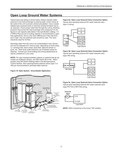
Open Loop Ground Water Systems<br />
Typical open loop piping is shown below. Always maintain water<br />
pressure in the heat exchanger by placing water control valves at<br />
the outlet of the unit to prevent mineral precipitation. Use a closed,<br />
bladder-type expansion tank to minimize mineral formation due to<br />
air exposure. Insure proper water flow through the unit by checking<br />
pressure drop across the heat exchanger and comparing it to the<br />
figures in unit capacity data tables in the specification catalog. 1.5-<br />
2 GPM of flow per ton of cooling capacity is recommended in open<br />
loop applications. Due to only minor differences in flow rate from<br />
low to high, only one solenoid valve should be used. The valve<br />
should be sized for full flow.<br />
Discharge water from the unit is not contaminated in any manner<br />
and can be disposed of in various ways, depending on local codes,<br />
i.e. recharge well, storm sewer, drain field, adjacent stream or<br />
pond, etc. Most local codes forbid the use of sanitary sewer for<br />
disposal. Consult your local building and zoning departments to<br />
assure compliance in your area.<br />
NOTE: For open loop/groundwater systems or systems that do not<br />
contain an antifreeze solution, set SW2-Switch #2 to the “WELL”<br />
position (see DIP Switch Settings table in the Microprocessor<br />
Control section). Slow opening/closing solenoid valves (type V or<br />
VM) are recommended to eliminate water hammer.<br />
Figure 10: Open System - Groundwater Application<br />
Unit Supply<br />
Figure 9a: Open Loop Solenoid Valve Connection Option<br />
Typical slow operating external 24V water solenoid valve<br />
(type V) wiring.<br />
C<br />
W/Y<br />
V Valve<br />
Figure 9b: Open Loop Solenoid Valve Connection Option<br />
Typical slow operating external 24V water solenoid valve<br />
(type VM) wiring.<br />
VM Valve<br />
C<br />
R<br />
Acc Com<br />
ACC NC<br />
Acc NO<br />
Logic ABC Board<br />
C<br />
R<br />
Acc Com<br />
ACC NC<br />
Acc NO<br />
Logic<br />
ABC Board<br />
Board<br />
Aux. Heat Supply<br />
Flexible<br />
Duct Collar<br />
Rubber Bladder<br />
Expansion Tank<br />
Figure 9c: Open Loop Solenoid Valve Connection Option<br />
Typical quick operating external 24V water solenoid valve<br />
(type PPV100 or BPV100) wiring.<br />
Disconnects<br />
(IfApplicable)<br />
Compressor<br />
Line Voltage<br />
Low Voltage<br />
to Thermostat<br />
and Valve<br />
P/T Plugs<br />
Vibration<br />
Absorbing Pad<br />
Auxiliary<br />
Heater<br />
Knockout<br />
Desuperheater<br />
Connections<br />
Drain<br />
Strainer<br />
Solenoid<br />
Valve<br />
Boiler Drains<br />
For HX Flushing<br />
Flow Control<br />
Valve<br />
(on outlet of<br />
Solenoid Valve)<br />
Water Out<br />
Water In<br />
Shut Off Valves<br />
Shut Off Valves<br />
(to isolate solenoid<br />
valve while acid flushing)<br />
Solenoid<br />
Valve<br />
SV<br />
CCHI<br />
CC-GND<br />
Logic Board<br />
NOTE: SW2-3 should be in the Comp “ON” position.<br />
11