Premium G Install Manual - GeoSmart Energy
Premium G Install Manual - GeoSmart Energy
Premium G Install Manual - GeoSmart Energy

Create successful ePaper yourself
Turn your PDF publications into a flip-book with our unique Google optimized e-Paper software.
PREMIUM G SERIES INSTALLATION MANUAL<br />
General <strong>Install</strong>ation Information cont.<br />
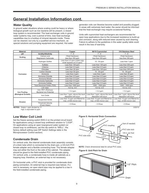
Water Quality<br />
In ground water situations where scaling could be heavy or where<br />
biological growth such as iron bacteria will be present, a closed<br />
loop system is recommended. The heat exchanger coils in ground<br />
water systems may, over a period of time, lose heat exchange<br />
capabilities due to a buildup of mineral deposits inside. These<br />
can be cleaned, but only by a qualified service mechanic, as<br />
special solutions and pumping equipment are required. Hot water<br />
generator coils can likewise become scaled and possibly plugged.<br />
In areas with extremely hard water, the owner should be informed<br />
that the heat exchanger may require occasional flushing.<br />
Units with cupronickel heat exchangers are recommended for<br />
open loop applications due to the increased resistance to build-up<br />
and corrosion, along with reduced wear caused by acid cleaning.<br />
Failure to adhere to the guidelines in the water quality table could<br />
result in the loss of warranty.<br />
Material Copper 90/10 Cupronickel 316 Stainless Steel<br />
pH Acidity/Alkalinity 7 - 9 7 - 9 7 - 9<br />
Scaling<br />
Calcium and<br />
(Total Hardness)<br />
(Total Hardness)<br />
(Total Hardness)<br />
Magnesium Carbonate<br />
less than 350 ppm<br />
less than 350 ppm<br />
less than 350 ppm<br />
Hydrogen Sulfide<br />
Less than 0.5 ppm (rotten egg<br />
smell appears at 0.5 ppm)<br />
10 - 50 ppm Less than 1 ppm<br />
Sulfates Less than 125 ppm Less than 125 ppm Less than 200 ppm<br />
Chlorine Less than 0.5 ppm Less than 0.5 ppm Less than 0.5 ppm<br />
Chlorides Less than 20 ppm Less than 125 ppm Less than 300 ppm<br />
Carbon Dioxide Less than 50 ppm 10 - 50 ppm 10 - 50 ppm<br />
Corrosion<br />
Ammonia Less than 2 ppm Less than 2 ppm Less than 20 ppm<br />
Ammonia Chloride Less than 0.5 ppm Less than 0.5 ppm Less than 0.5 ppm<br />
Ammonia Nitrate Less than 0.5 ppm Less than 0.5 ppm Less than 0.5 ppm<br />
Ammonia Hydroxide Less than 0.5 ppm Less than 0.5 ppm Less than 0.5 ppm<br />
Ammonia Sulfate Less than 0.5 ppm Less than 0.5 ppm Less than 0.5 ppm<br />
Total Dissolved Solids (TDS) Less than 1000 ppm 1000 - 1500 ppm 1000 - 1500 ppm<br />
LSI Index +0.5 to -0.5 +0.5 to -0.5 +0.5 to -0.5<br />
Iron, FE 2 + (Ferrous)<br />
Iron Fouling<br />
Bacterial Iron Potential<br />
< 0.2 ppm < 0.2 ppm < 0.2 ppm<br />
(Biological Growth)<br />
Less than 1 ppm, above this level Less than 1 ppm, above this level Less than 1 ppm, above this level<br />
Iron Oxide<br />
deposition will occur<br />
deposition will occur<br />
deposition will occur<br />
Suspended Solids<br />
Erosion<br />
Threshold Velocity<br />
(Fresh Water)<br />
NOTES: Grains = ppm divided by 17<br />
mg/L is equivalent to ppm<br />
Less than 10 ppm and filtered for<br />
max. of 600 micron size<br />
Less than 10 ppm and filtered for<br />
max. of 600 micron size<br />
Less than 10 ppm and filtered for<br />
max. of 600 micron size<br />
< 6 ft/sec < 6 ft/sec < 6 ft/sec<br />
2/22/12<br />
Low Water Coil Limit<br />
Set the freeze sensing switch SW2-2 on the printed circuit board<br />
for applications using a closed loop antifreeze solution to “LOOP”.<br />
On applications using an open loop/ground water system (or<br />
closed loop no antifreeze), set this dip switch to “WELL”, the<br />
factory default setting (see DIP Switch Settings table in the<br />
Microprocessor Control section).<br />
Condensate Drain<br />
On vertical units, the internal condensate drain assembly consists<br />
of a drain tube which is connected to the drain pan, a 3/4-inch PVC<br />
female adapter and a flexible connecting hose. The female adapter<br />
may exit either the front or the side of the cabinet. The adapter<br />
should be glued to the field-installed PVC condensate piping.<br />
On vertical units, a condensate hose is inside all cabinets as a<br />
trapping loop; therefore, an external trap is not necessary.<br />
On horizontal units, a PVC stub is provided for condensate drain<br />
piping connection. An external trap is required (see below). If a<br />
vent is necessary, an open stand pipe may be applied to a tee in<br />
the field-installed condensate piping.<br />
Figure 5: Horizontal Drain Connection<br />
Vent (if needed)<br />
PVC coupling<br />
PVC tube stub<br />
1/8 in. per foot<br />
PVC tube stub<br />
1.5 in.<br />
1.5 in.<br />
NOTE: Check dimensional data for actual PVC sizes.<br />
Figure 6: Unit Pitch for Drain<br />
1/2'' Pitch<br />
Drain<br />
9