Premium G Install Manual - GeoSmart Energy
Premium G Install Manual - GeoSmart Energy
Premium G Install Manual - GeoSmart Energy

Create successful ePaper yourself
Turn your PDF publications into a flip-book with our unique Google optimized e-Paper software.
PREMIUM G SERIES INSTALLATION MANUAL<br />
Microprocessor Control System cont.<br />
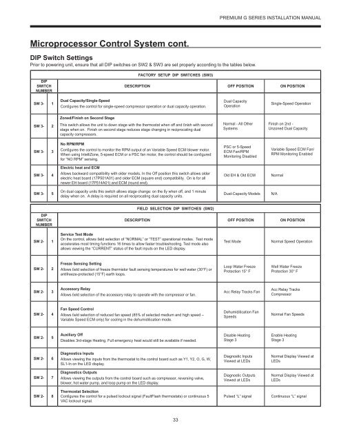
DIP Switch Settings<br />
Prior to powering unit, ensure that all DIP switches on SW2 & SW3 are set properly according to the tables below.<br />
DIP<br />
SWITCH<br />
NUMBER<br />
FACTORY SETUP DIP SWITCHES (SW3)<br />
DESCRIPTION OFF POSITION ON POSITION<br />
SW 3- 1<br />
Dual Capacity/Single-Speed<br />
Confi gures the control for single-speed compressor operation or dual capacity operation.<br />
Dual Capacity<br />
Operation<br />
Single-Speed Operation<br />
Zoned/Finish on Second Stage<br />
SW 3- 2<br />
This switch allows the unit to down stage with the thermostat when off and fi nish with second<br />
stage when on. Finish on second stage reduces stage changing in reciprocating dual<br />
capacity compressors.<br />
Normal - All Other<br />
Systems<br />
Finish on 2nd -<br />
Unzoned Dual Capacity<br />
SW 3- 3<br />
No RPM/RPM<br />
Confi gures the control to monitor the RPM output of an Variable Speed ECM blower motor.<br />
When using IntelliZone, 5-speed ECM or a PSC fan motor, the control should be confi gured<br />
for “NO RPM” sensing.<br />
PSC or 5-Speed<br />
ECM Fan/RPM<br />
Monitoring Disabled<br />
Variable Speed ECM Fan/<br />
RPM Monitoring Enabled<br />
Electric heat and ECM<br />
SW 3- 4<br />
Allows backward compatibility with older models. In the Off position this switch allows older<br />
electric heat board (17P501A01) and older ECM (square end) compatibility. On is for all<br />
newer EH board (17P514A01) and ECM (round end).<br />
Old EH & Old ECM<br />
Normal<br />
SW 3- 5<br />
On dual capacity units this switch allows stage change: on the fl y when off, and 1 minute<br />
delay when on. A delay is required on all reciprocating dual capacity units.<br />
Dual-Capacity Models<br />
N/A<br />
FIELD SELECTION DIP SWITCHES (SW2)<br />
DIP<br />
SWITCH<br />
NUMBER<br />
DESCRIPTION OFF POSITION ON POSITION<br />
SW 2- 1<br />
Service Test Mode<br />
On the control, allows fi eld selection of “NORMAL” or “TEST” operational modes. Test mode<br />
accelerates most timing functions 16 times to allow faster troubleshooting. Test mode also<br />
allows viewing the “CURRENT” status of the fault inputs on the LED display.<br />
Test Mode<br />
Normal Speed Operation<br />
SW 2- 2<br />
Freeze Sensing Setting<br />
Allows fi eld selection of freeze thermistor fault sensing temperatures for well water (30°F) or<br />
antifreeze-protected (15°F) earth loops.<br />
Loop Water Freeze<br />
Protection 15° F<br />
Well Water Freeze<br />
Protection 30° F<br />
SW 2- 3<br />
Accessory Relay<br />
Allows fi eld selection of the accessory relay to operate with the compressor or fan.<br />
Acc Relay Tracks Fan<br />
Acc Relay Tracks<br />
Compressor<br />
SW 2- 4<br />
Fan Speed Control<br />
Allows fi eld selection of reduced fan speed (85% of selected medium and high speed –<br />
Variable Speed ECM only) for cooling in the dehumidifi cation mode.<br />
Dehumidifi cation Fan<br />
Speeds<br />
Normal Fan Speeds<br />
SW 2- 5<br />
Auxiliary Off<br />
Disables 3rd-stage Heating. Full emergency heat would still be available if needed.<br />
Disable Heating<br />
Stage 3<br />
Enable Heating<br />
Stage 3<br />
SW 2- 6<br />
Diagnostics Inputs<br />
Allows viewing the inputs from the thermostat to the control board such as Y1, Y2, O, G, W,<br />
SL1-In on the LED display.<br />
Diagnostic Inputs<br />
Viewed at LEDs<br />
Normal Display Viewed at<br />
LEDs<br />
SW 2- 7<br />
Diagnostics Outputs<br />
Allows viewing the outputs from the control board such as compressor, reversing valve,<br />
blower, hot water pump, and loop pump on the LED display.<br />
Diagnostic Outputs<br />
Viewed at LEDs<br />
Normal Display Viewed at<br />
LEDs<br />
SW 2- 8<br />
Thermostat Selection<br />
Confi gures the control for a pulsed lockout signal (FaultFlash thermostats) or continuous 5<br />
VAC lockout signal.<br />
Pulsed “L” signal<br />
Continuous “L” signal<br />
33