20 GEIGER ET AL. (2007) MOLLUSCAN RESEARCH, VOL. 27
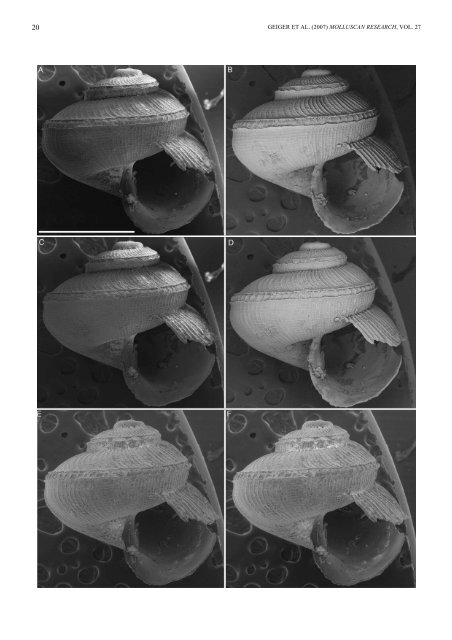
TECHNIQUES FOR STUDYING SMALL MOLLUSCAN SPECIMENS 21 FIGURE 7. Illustration of different SEM imaging techniques applied to the same specimen sputter coated with gold. The shell is somewhat eroded, which often leads to greater problems with charging. As eroded specimens are often also more fragile, the specimen could only be superficially cleaned, with the remaining debris further enhancing charging problems. All images taken with Zeiss EVO40XVP at 20 kV, 10 mm working distance, and 100 pA probe current (except F). A–D. High vacuum; integration of 25 frames, total imaging time 1.5 minutes; line integration produced heavy charging artefacts (not shown). A. 100% secondary electron detector. Notice uneven illumination in upper right portion of shell. B. Two lower left-hand quadrants of backscatter detector. C. Signal mixing of 75% secondary electron detector from A and 25% backscatter detector from B. Notice the more even overall illumination as the backscatter signal is used to brighten up the dark portion of the shell. D. 100% backscatter detector with all four quadrants active. E, F. Variable pressure mode with chamber pressure at 30 Pa, line integration <strong>for</strong> 1.5 minutes. E. Variable pressure secondary electron detector (VPSE) with 100 pA probe current. F. VPSE with 200 pA probe current. Notice greater charging effects at suture. Anatoma proxima (Dall, 1927) (USNM 449418), Scale bar = 1 mm. Images DLG. The secondary electron detector attracts the negatively charged secondary electrons with a bias voltage of around +300 V (Fig. 8A). If the bias voltage is set to –50 V (Fig. 8C), the secondary electrons are repelled, while the highenergy backscatter electrons with straight trajectories can overcome the slight bias barrier. With more negative bias voltage the effect can be further enhanced (Fig. 8D). As the electron yield is smaller, a higher probe current is usually necessary. The contribution of secondary and backscatter electrons can be varied continuously, by adjusting the bias voltage between 0 and –50 V. Specimen removal from stubs Specimens can be removed from carbon tabs and double-sided tape in dry condition if necessary, but the bond, particularly between carbon tabs and shells, is rather strong and specimens may break when attempting to remove them from the tab. This tendency becomes more pronounced once the carbon tab has been exposed to high vacuum. Specimens can be removed from the carbon tabs using 95–100% ethanol, either to remount specimens <strong>for</strong> additional views, or to be returned to the specimen vial. Cleaning colloidal graphite from a shell requires multiple washes in isopropanol or 80% ethanol. Uncoated carbon tabs can be reused a few times (e.g., when imaging type specimens). Repeated exposure to ethanol makes the glue less sticky. Specimens can be remounted on coated tabs if the mounting spot is rubbed with a blunt pin to remove the gold coat on its surface. Spray-glued specimens can easily be removed from the stub and returned to the original lot. The glue can be dissolved in butyl acetate or acetone (neither of which are very toxic nor do they evaporate too quickly), or chloro<strong>for</strong>m. These solvents are also used <strong>for</strong> cleaning used stubs. Separating the valves of minute bivalves Small wet or dry bivalves may be difficult to open since they are firmly stuck together. Avoid trying to open these when dry. The specimens, with or without the animal, should be initially passed through ethanol to break surface tension, then soaked <strong>for</strong> several hours or even a day or two in water containing a little detergent. Some additional techniques are outlined below, the choice depending on the degree of overlap at the valve margins and whether or not a little damage to the ventral margin of the valves can be accepted. • Do in a vacuum, where enclosed air may exert sufficient pressure to push the valves open slightly. • If there is little or no valve overlap, view under a stereomicroscope (and moisten periodically), while placing the specimen with one end against the thumb and the other against the <strong>for</strong>efinger (right handers) of the left hand, with the anterior or posterior end uppermost and the ventral margin facing right. In this way the valves may separate slightly, making it easier to insert the point of a scalpel or mounted razor blade fragment (a blade spreads <strong>for</strong>ces over a wide area, unlike needles or <strong>for</strong>ceps which are more liable to break or damage the valves). As soon as the tip is inserted, the bivalve can be held with the blade and cautiously pushed with its back against the finger and, if a preserved specimen, the adductor muscles cut. • Cutting the adductor muscles can also be achieved by carefully moving the specimen towards a fresh blade held vertically between the thumb and two <strong>for</strong>efingers of the right hand, the objective being to place the ventral meeting point of the valve margins squarely against the blade. • Soaked specimens can be placed in a specimen tube half filled with water and connected by a tube passing through a closure to a standard, water-driven, laboratory vacuum pump, repeatedly applying vacuum via a valve or hose clamp, with the aim of parting the valves sufficiently <strong>for</strong> them to be opened with a blade. • Very small or very fragile bivalves can be soaked in warm, diluted bleach so that a bubble of chlorine will push the valves open. Use a paint brush (with artificial hair!) or a fine pipette <strong>for</strong> <strong>handling</strong> the specimens. This method is unsuitable <strong>for</strong> highly nacreous shells, which are sensitive to bleach. Instead use weak hydrogen peroxide with a trace of KOH added to make it basic. Note that sodium lauryl sulphate is not suitable as it takes longer and does not open the valves, it only dissolves the soft tissues, not the ligament composed of tanned proteins. SEM imaging Specimens should be illustrated in standardised views. For gastropods, the coiling axis of the shell should be parallel or at a right angle to the image plane. In apertural view, showing a little of the outside of the outer lip allows better