- Page 2:
Practical Industrial Data Networks:
- Page 6:
Practical Industrial Data Networks:
- Page 10:
PrefaceContentsxiii1 Introduction 1
- Page 14:
Contents vii6.8.4 Fiber installatio
- Page 18:
Contents ix12.7.3 Single supply - c
- Page 22:
Contents xi15.5.7 Switching technol
- Page 26:
PrefaceThis is a comprehensive book
- Page 30:
PrefacexvChapter 9: Data Highway Pl
- Page 34:
1IntroductionObjectivesWhen you hav
- Page 38:
Introduction 3have largely been rep
- Page 42:
Introduction 5OperatorstationOperat
- Page 46:
Introduction 7Real WorldReal WorldA
- Page 50:
Introduction 9• A suitable receiv
- Page 54:
Introduction 11This is widely used
- Page 58:
AS-iIntroduction 13This must be one
- Page 62:
Introduction 15the token passing me
- Page 66:
2Overall methodologyObjectivesWhen
- Page 70:
Watch out for deviationsOverall met
- Page 76:
22Practical Industrial Data Network
- Page 80:
24Practical Industrial Data Network
- Page 84:
26Practical Industrial Data Network
- Page 88:
28Practical Industrial Data Network
- Page 92:
30Practical Industrial Data Network
- Page 96:
3EIA-232 overviewObjectivesWhen you
- Page 100:
34Practical Industrial Data Network
- Page 104:
36Practical Industrial Data Network
- Page 108:
38Practical Industrial Data Network
- Page 112:
40Practical Industrial Data Network
- Page 116:
42Practical Industrial Data Network
- Page 120:
44Practical Industrial Data Network
- Page 124:
46Practical Industrial Data Network
- Page 128:
48Practical Industrial Data Network
- Page 132:
50Practical Industrial Data Network
- Page 136:
52Practical Industrial Data Network
- Page 140:
54Practical Industrial Data Network
- Page 144:
56Practical Industrial Data Network
- Page 148:
58Practical Industrial Data Network
- Page 152:
60Practical Industrial Data Network
- Page 156:
62Practical Industrial Data Network
- Page 160:
64Practical Industrial Data Network
- Page 164:
66Practical Industrial Data Network
- Page 168:
68Practical Industrial Data Network
- Page 172:
70Practical Industrial Data Network
- Page 176:
72Practical Industrial Data Network
- Page 180:
6Fiber optics overviewObjectivesWhe
- Page 184:
76Practical Industrial Data Network
- Page 188:
78Practical Industrial Data Network
- Page 192:
80Practical Industrial Data Network
- Page 196:
82Practical Industrial Data Network
- Page 200:
84Practical Industrial Data Network
- Page 204:
86Practical Industrial Data Network
- Page 208:
88Practical Industrial Data Network
- Page 212:
90Practical Industrial Data Network
- Page 216:
92Practical Industrial Data Network
- Page 220:
94Practical Industrial Data Network
- Page 224:
7Modbus overviewObjectivesWhen you
- Page 228:
98Practical Industrial Data Network
- Page 232:
100 Practical Industrial Data Netwo
- Page 236:
102 Practical Industrial Data Netwo
- Page 240:
104 Practical Industrial Data Netwo
- Page 244:
106 Practical Industrial Data Netwo
- Page 248:
108 Practical Industrial Data Netwo
- Page 252:
110 Practical Industrial Data Netwo
- Page 256:
112 Practical Industrial Data Netwo
- Page 260:
114 Practical Industrial Data Netwo
- Page 264:
116 Practical Industrial Data Netwo
- Page 268:
118 Practical Industrial Data Netwo
- Page 272:
120 Practical Industrial Data Netwo
- Page 276: 122 Practical Industrial Data Netwo
- Page 280: 124 Practical Industrial Data Netwo
- Page 284: 126 Practical Industrial Data Netwo
- Page 288: 128 Practical Industrial Data Netwo
- Page 292: 130 Practical Industrial Data Netwo
- Page 296: 132 Practical Industrial Data Netwo
- Page 300: 134 Practical Industrial Data Netwo
- Page 304: 136 Practical Industrial Data Netwo
- Page 308: 138 Practical Industrial Data Netwo
- Page 312: PREVIOUSFUNCTION140 Practical Indus
- Page 316: 142 Practical Industrial Data Netwo
- Page 320: 144 Practical Industrial Data Netwo
- Page 324: 146 Practical Industrial Data Netwo
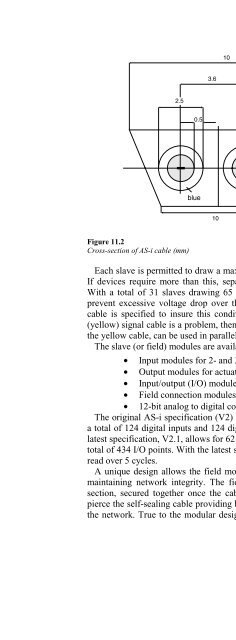
- Page 330: AS-interface (AS-i) overview 149Fig
- Page 334: AS-interface (AS-i) overview 1515 B
- Page 338: AS-interface (AS-i) overview 153•
- Page 342: 12DeviceNet overviewObjectivesWhen
- Page 346: DeviceNet overview 157NodeNodeTrunk
- Page 350: DeviceNet overview 159Important: Th
- Page 354: DeviceNet overview 161DATA RATES 12
- Page 358: DeviceNet overview 163Trunk orDropL
- Page 362: 12.6 Cable descriptionDeviceNet ove
- Page 366: DeviceNet overview 16712.7 Network
- Page 370: DeviceNet overview 169Current in se
- Page 374: DeviceNet overview 171With no netwo
- Page 378:
DeviceNet overview 173busRecessiveD
- Page 382:
MultimeterDeviceNet overview 175A m
- Page 386:
DeviceNet overview 177A PC with thi
- Page 390:
DeviceNet overview 17912.12.3.5 Com
- Page 394:
13ProfiBus PA/DP/FMS overviewObject
- Page 398:
13.2 ProfiBus protocol stackProfiBu
- Page 402:
ProfiBus PA/DP/FMS overview 185Figu
- Page 406:
13.2.3 Application layerProfiBus PA
- Page 410:
ProfiBus PA/DP/FMS overview 189•
- Page 414:
ProfiBus PA/DP/FMS overview 191Real
- Page 418:
ProfiBus PA/DP/FMS overview 193•
- Page 422:
ProfiBus PA/DP/FMS overview 195If t
- Page 426:
ProfiBus PA/DP/FMS overview 197Figu
- Page 430:
ProfiBus PA/DP/FMS overview 199•
- Page 434:
Foundation Fieldbus overview 201bus
- Page 438:
Foundation Fieldbus overview 203Bou
- Page 442:
Foundation Fieldbus overview 205The
- Page 446:
Foundation Fieldbus overview 207ope
- Page 450:
Foundation Fieldbus overview 209Onc
- Page 454:
Foundation Fieldbus overview 211Whe
- Page 458:
Foundation Fieldbus overview 213Fig
- Page 462:
Foundation Fieldbus overview 215Fig
- Page 466:
Industrial Ethernet overview 217rel
- Page 470:
Industrial Ethernet overview 219The
- Page 474:
Industrial Ethernet overview 221At
- Page 478:
15.2.2 Signaling methodsIndustrial
- Page 482:
Industrial Ethernet overview 225Pre
- Page 486:
Industrial Ethernet overview 2271 b
- Page 490:
5 segments4 repeaters3 coax segment
- Page 494:
Industrial Ethernet overview 231dom
- Page 498:
Industrial Ethernet overview 233The
- Page 502:
Industrial Ethernet overview 235Tab
- Page 506:
Industrial Ethernet overview 237twi
- Page 510:
Industrial Ethernet overview 239wil
- Page 514:
Industrial Ethernet overview 24115.
- Page 518:
Industrial Ethernet overview 243An
- Page 522:
Industrial Ethernet overview 245cab
- Page 526:
Industrial Ethernet overview 247Inc
- Page 530:
T4 on 2 pairsIndustrial Ethernet ov
- Page 534:
Industrial Ethernet overview 251The
- Page 538:
Industrial Ethernet overview 253Fau
- Page 542:
Industrial Ethernet overview 255obs
- Page 546:
16TCP/IP overviewObjectivesWhen you
- Page 550:
16.1.1 The Internet layerTCP/IP ove
- Page 554:
TCP/IP overview 261if IP is NOT all
- Page 558:
TCP/IP overview 263To overcome thes
- Page 562:
TCP/IP overview 26516.2.3 ICMPTarge
- Page 566:
TCP/IP overview 267Type field034581
- Page 570:
TCP/IP overview 269host outside the
- Page 574:
16.3.2 UDPTCP/IP overview 271data w
- Page 578:
TCP/IP overview 27316.4.3.3 Softwar
- Page 582:
TCP/IP overview 275Not being able t
- Page 586:
17Radio and wireless communications
- Page 590:
Radio and wireless communications o
- Page 594:
Radio and wireless communications o
- Page 598:
Radio and wireless communications o
- Page 602:
Radio and wireless communications o
- Page 606:
Radio channel data rateRadio and wi
- Page 610:
Radio and wireless communications o
- Page 614:
Radio and wireless communications o
- Page 618:
Radio and wireless communications o
- Page 622:
Radio and wireless communications o
- Page 626:
Radio and wireless communications o
- Page 630:
Appendix A - Glossary 299Analoga co
- Page 634:
BroadbandBroadcastBSBSBSCBSPBufferB
- Page 638:
Appendix A - Glossary 303DCDDCEDCSD
- Page 642:
Filled cableFIPFirmwareFlame retard
- Page 646:
Appendix A - Glossary 307ISOISPISRI
- Page 650:
Appendix A - Glossary 309MOSMOVMSBM
- Page 654:
Appendix A - Glossary 311Presentati
- Page 658:
Appendix A - Glossary 313written in
- Page 662:
WANWordAppendix A - Glossary 315wid
- Page 666:
Appendix B - Basic terminology 317T
- Page 670:
Appendix B - Basic terminology 319S
- Page 674:
Two frequency allocationAppendix B
- Page 678:
Appendix B - Basic terminology 323B
- Page 682:
Appendix B - Basic terminology 325G
- Page 686:
Appendix B - Basic terminology 327s
- Page 690:
Appendix B - Basic terminology 329B
- Page 694:
Appendix B - Basic terminology 331B
- Page 698:
Appendix B - Basic terminology 333F
- Page 702:
Appendix B - Basic terminology 335F
- Page 706:
Appendix B - Basic terminology 337F
- Page 710:
Appendix B - Basic terminology 339F
- Page 714:
Appendix B - Basic terminology 341
- Page 718:
Appendix CPracticalsPractical and e
- Page 722:
Appendix C - Practicals 3452. Which
- Page 726:
Appendix C - Practicals 347Note: In
- Page 730:
Appendix C - Practicals 3499. Press
- Page 734:
Appendix C - Practicals 351Practica
- Page 738:
Timing analysisAppendix C - Practic
- Page 742:
• To demonstrate the use of Devic
- Page 746:
Conclusion• Current in section 1
- Page 750:
Appendix C - Practicals 35910 mA10
- Page 754:
Appendix C - Practicals 361Note tha
- Page 758:
Appendix C - Practicals 363Check th
- Page 762:
Appendix C - Practicals 365Finally,
- Page 766:
Appendix C - Practicals 367Notice t
- Page 770:
ConclusionAppendix C - Practicals 3
- Page 774:
Appendix C - Practicals 371network
- Page 778:
Appendix C - Practicals 373If there
- Page 782:
ImplementationAppendix C - Practica
- Page 786:
Appendix C - Practicals 377Click on
- Page 790:
Appendix C - Practicals 379To view
- Page 794:
Appendix C - Practicals 381Note the
- Page 798:
Hardware/software requiredAppendix
- Page 802:
Appendix C - Practicals 385Notice t
- Page 806:
Appendix C - Practicals 387Reconnec
- Page 810:
ConclusionAppendix C - Practicals 3
- Page 814:
Appendix C - Practicals 391Ensure t
- Page 818:
Name it ‘EnableRouting.’Appendi
- Page 822:
Appendix C - Practicals 395Restart
- Page 826:
Appendix C - Practicals 397Note the
- Page 830:
ConclusionAppendix C - Practicals 3
- Page 834:
ConclusionAppendix C - Practicals 4
- Page 838:
Appendix D - Miscellaneous industri
- Page 842:
Appendix D - Miscellaneous industri
- Page 846:
Appendix E - Local services, regula
- Page 850:
Appendix E - Local services, regula
- Page 854:
Appendix E - Local services, regula
- Page 858:
MOBILESATAppendix E - Local service
- Page 862:
IndexAllen Bradley, 11, 13Allen Bra
- Page 866:
Index 417thin coax problems, 244-6t
- Page 870:
Index 419Network interface card (NI
- Page 874:
Index 421fiber optics:continuity te