- Page 2: Practical Industrial Data Networks:
- Page 6: Practical Industrial Data Networks:
- Page 10: PrefaceContentsxiii1 Introduction 1
- Page 14: Contents vii6.8.4 Fiber installatio
- Page 18: Contents ix12.7.3 Single supply - c
- Page 22: Contents xi15.5.7 Switching technol
- Page 26: PrefaceThis is a comprehensive book
- Page 30: PrefacexvChapter 9: Data Highway Pl
- Page 34: 1IntroductionObjectivesWhen you hav
- Page 38: Introduction 3have largely been rep
- Page 42: Introduction 5OperatorstationOperat
- Page 46: Introduction 7Real WorldReal WorldA
- Page 52: 10Practical Industrial Data Network
- Page 56: 12Practical Industrial Data Network
- Page 60: 14Practical Industrial Data Network
- Page 64: 16Practical Industrial Data Network
- Page 68: 18Practical Industrial Data Network
- Page 72: 20Practical Industrial Data Network
- Page 78: Overall methodology 23times or 20 d
- Page 82: Overall methodology 25di Noise Sour
- Page 86: Overall methodology 27comparison, p
- Page 90: Overall methodology 29• To ensure
- Page 94: Overall methodology 31Typical sourc
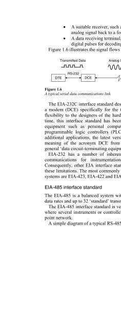
- Page 98: EIA-232 overview 33The EIA-232 inte
- Page 102:
EIA-232 overview 35DTE DeviceDCE De
- Page 106:
Pin no.DTEEIA-232 overview 37(9-pin
- Page 110:
• Ring indicatorThis pin is asser
- Page 114:
EIA-232 overview 41User Terminal(DT
- Page 118:
EIA-232 overview 433.5.2 Typical ap
- Page 122:
EIA-232 overview 45TestPointsDTEDCE
- Page 126:
EIA-232 overview 47Figure 3.8Protoc
- Page 130:
EIA-232 overview 493.5.4.1 Mechanic
- Page 134:
Ground induced noiseEIA-232 overvie
- Page 138:
4EIA-485 overviewObjectivesWhen you
- Page 142:
EIA-485 overview 551200M (4000 FT)A
- Page 146:
EIA-485 overview 57In addition, the
- Page 150:
EIA-485 overview 59Figure 4.6EIA-48
- Page 154:
EIA-485 overview 61Serious problems
- Page 158:
EIA-485 overview 63+VRinging-VFigur
- Page 162:
EIA-485 overview 65therefore braide
- Page 166:
RingingEIA-485 overview 67Ringing i
- Page 170:
5Current loop and EIA-485converters
- Page 174:
Current loop and EIA-485 converters
- Page 178:
Current loop and EIA-485 converters
- Page 182:
Fiber optics overview 75N 1N 2N 1N
- Page 186:
Fiber optics overview 77fibers (con
- Page 190:
Fiber optics overview 79changing ab
- Page 194:
Fiber optics overview 816.5.2 Under
- Page 198:
6.6.3 ConnectorsFiber optics overvi
- Page 202:
6.7.1 Splicing traysFiber optics ov
- Page 206:
Fiber optics overview 87StrippedInc
- Page 210:
Fiber optics overview 896.8.3 Tools
- Page 214:
6.8.5 Clean optical connectorsFiber
- Page 218:
Fiber optics overview 93a) Calibrat
- Page 222:
Fiber optics overview 95has probabl
- Page 226:
Modbus overview 97• While it is e
- Page 230:
7.3.1 Read coil or digital output s
- Page 234:
Modbus overview 101The data field o
- Page 238:
Modbus overview 103Request MessageA
- Page 242:
Modbus overview 105Request MessageA
- Page 246:
Modbus overview 107Request FrameAdd
- Page 250:
Modbus overview 1097.4 Troubleshoot
- Page 254:
Modbus overview 111In case I, the m
- Page 258:
Modbus overview 113• Use the GND
- Page 262:
8Modbus Plus protocol overviewObjec
- Page 266:
Modbus Plus protocol overview 117ne
- Page 270:
Modbus active LEDModbus Plus protoc
- Page 274:
Modbus Plus protocol overview 121ei
- Page 278:
Modbus Plus protocol overview 123SA
- Page 282:
9Data Highway Plus/DH485 overviewOb
- Page 286:
Data Highway Plus/DH485 overview 12
- Page 290:
Data Highway Plus/DH485 overview 12
- Page 294:
Data Highway Plus/DH485 overview 13
- Page 298:
Data Highway Plus/DH485 overview 13
- Page 302:
Data Highway Plus/DH485 overview 13
- Page 306:
10HART overviewObjectivesWhen you h
- Page 310:
HART overview 139In the poll/respon
- Page 314:
F1 F2 F3 F4ON/OFFREVIEWPREVIOUSHELP
- Page 318:
HART overview 143• Trim pv zero
- Page 322:
11AS-interface (AS-i) overviewObjec
- Page 326:
AS-interface (AS-i) overview 147103
- Page 330:
AS-interface (AS-i) overview 149Fig
- Page 334:
AS-interface (AS-i) overview 1515 B
- Page 338:
AS-interface (AS-i) overview 153•
- Page 342:
12DeviceNet overviewObjectivesWhen
- Page 346:
DeviceNet overview 157NodeNodeTrunk
- Page 350:
DeviceNet overview 159Important: Th
- Page 354:
DeviceNet overview 161DATA RATES 12
- Page 358:
DeviceNet overview 163Trunk orDropL
- Page 362:
12.6 Cable descriptionDeviceNet ove
- Page 366:
DeviceNet overview 16712.7 Network
- Page 370:
DeviceNet overview 169Current in se
- Page 374:
DeviceNet overview 171With no netwo
- Page 378:
DeviceNet overview 173busRecessiveD
- Page 382:
MultimeterDeviceNet overview 175A m
- Page 386:
DeviceNet overview 177A PC with thi
- Page 390:
DeviceNet overview 17912.12.3.5 Com
- Page 394:
13ProfiBus PA/DP/FMS overviewObject
- Page 398:
13.2 ProfiBus protocol stackProfiBu
- Page 402:
ProfiBus PA/DP/FMS overview 185Figu
- Page 406:
13.2.3 Application layerProfiBus PA
- Page 410:
ProfiBus PA/DP/FMS overview 189•
- Page 414:
ProfiBus PA/DP/FMS overview 191Real
- Page 418:
ProfiBus PA/DP/FMS overview 193•
- Page 422:
ProfiBus PA/DP/FMS overview 195If t
- Page 426:
ProfiBus PA/DP/FMS overview 197Figu
- Page 430:
ProfiBus PA/DP/FMS overview 199•
- Page 434:
Foundation Fieldbus overview 201bus
- Page 438:
Foundation Fieldbus overview 203Bou
- Page 442:
Foundation Fieldbus overview 205The
- Page 446:
Foundation Fieldbus overview 207ope
- Page 450:
Foundation Fieldbus overview 209Onc
- Page 454:
Foundation Fieldbus overview 211Whe
- Page 458:
Foundation Fieldbus overview 213Fig
- Page 462:
Foundation Fieldbus overview 215Fig
- Page 466:
Industrial Ethernet overview 217rel
- Page 470:
Industrial Ethernet overview 219The
- Page 474:
Industrial Ethernet overview 221At
- Page 478:
15.2.2 Signaling methodsIndustrial
- Page 482:
Industrial Ethernet overview 225Pre
- Page 486:
Industrial Ethernet overview 2271 b
- Page 490:
5 segments4 repeaters3 coax segment
- Page 494:
Industrial Ethernet overview 231dom
- Page 498:
Industrial Ethernet overview 233The
- Page 502:
Industrial Ethernet overview 235Tab
- Page 506:
Industrial Ethernet overview 237twi
- Page 510:
Industrial Ethernet overview 239wil
- Page 514:
Industrial Ethernet overview 24115.
- Page 518:
Industrial Ethernet overview 243An
- Page 522:
Industrial Ethernet overview 245cab
- Page 526:
Industrial Ethernet overview 247Inc
- Page 530:
T4 on 2 pairsIndustrial Ethernet ov
- Page 534:
Industrial Ethernet overview 251The
- Page 538:
Industrial Ethernet overview 253Fau
- Page 542:
Industrial Ethernet overview 255obs
- Page 546:
16TCP/IP overviewObjectivesWhen you
- Page 550:
16.1.1 The Internet layerTCP/IP ove
- Page 554:
TCP/IP overview 261if IP is NOT all
- Page 558:
TCP/IP overview 263To overcome thes
- Page 562:
TCP/IP overview 26516.2.3 ICMPTarge
- Page 566:
TCP/IP overview 267Type field034581
- Page 570:
TCP/IP overview 269host outside the
- Page 574:
16.3.2 UDPTCP/IP overview 271data w
- Page 578:
TCP/IP overview 27316.4.3.3 Softwar
- Page 582:
TCP/IP overview 275Not being able t
- Page 586:
17Radio and wireless communications
- Page 590:
Radio and wireless communications o
- Page 594:
Radio and wireless communications o
- Page 598:
Radio and wireless communications o
- Page 602:
Radio and wireless communications o
- Page 606:
Radio channel data rateRadio and wi
- Page 610:
Radio and wireless communications o
- Page 614:
Radio and wireless communications o
- Page 618:
Radio and wireless communications o
- Page 622:
Radio and wireless communications o
- Page 626:
Radio and wireless communications o
- Page 630:
Appendix A - Glossary 299Analoga co
- Page 634:
BroadbandBroadcastBSBSBSCBSPBufferB
- Page 638:
Appendix A - Glossary 303DCDDCEDCSD
- Page 642:
Filled cableFIPFirmwareFlame retard
- Page 646:
Appendix A - Glossary 307ISOISPISRI
- Page 650:
Appendix A - Glossary 309MOSMOVMSBM
- Page 654:
Appendix A - Glossary 311Presentati
- Page 658:
Appendix A - Glossary 313written in
- Page 662:
WANWordAppendix A - Glossary 315wid
- Page 666:
Appendix B - Basic terminology 317T
- Page 670:
Appendix B - Basic terminology 319S
- Page 674:
Two frequency allocationAppendix B
- Page 678:
Appendix B - Basic terminology 323B
- Page 682:
Appendix B - Basic terminology 325G
- Page 686:
Appendix B - Basic terminology 327s
- Page 690:
Appendix B - Basic terminology 329B
- Page 694:
Appendix B - Basic terminology 331B
- Page 698:
Appendix B - Basic terminology 333F
- Page 702:
Appendix B - Basic terminology 335F
- Page 706:
Appendix B - Basic terminology 337F
- Page 710:
Appendix B - Basic terminology 339F
- Page 714:
Appendix B - Basic terminology 341
- Page 718:
Appendix CPracticalsPractical and e
- Page 722:
Appendix C - Practicals 3452. Which
- Page 726:
Appendix C - Practicals 347Note: In
- Page 730:
Appendix C - Practicals 3499. Press
- Page 734:
Appendix C - Practicals 351Practica
- Page 738:
Timing analysisAppendix C - Practic
- Page 742:
• To demonstrate the use of Devic
- Page 746:
Conclusion• Current in section 1
- Page 750:
Appendix C - Practicals 35910 mA10
- Page 754:
Appendix C - Practicals 361Note tha
- Page 758:
Appendix C - Practicals 363Check th
- Page 762:
Appendix C - Practicals 365Finally,
- Page 766:
Appendix C - Practicals 367Notice t
- Page 770:
ConclusionAppendix C - Practicals 3
- Page 774:
Appendix C - Practicals 371network
- Page 778:
Appendix C - Practicals 373If there
- Page 782:
ImplementationAppendix C - Practica
- Page 786:
Appendix C - Practicals 377Click on
- Page 790:
Appendix C - Practicals 379To view
- Page 794:
Appendix C - Practicals 381Note the
- Page 798:
Hardware/software requiredAppendix
- Page 802:
Appendix C - Practicals 385Notice t
- Page 806:
Appendix C - Practicals 387Reconnec
- Page 810:
ConclusionAppendix C - Practicals 3
- Page 814:
Appendix C - Practicals 391Ensure t
- Page 818:
Name it ‘EnableRouting.’Appendi
- Page 822:
Appendix C - Practicals 395Restart
- Page 826:
Appendix C - Practicals 397Note the
- Page 830:
ConclusionAppendix C - Practicals 3
- Page 834:
ConclusionAppendix C - Practicals 4
- Page 838:
Appendix D - Miscellaneous industri
- Page 842:
Appendix D - Miscellaneous industri
- Page 846:
Appendix E - Local services, regula
- Page 850:
Appendix E - Local services, regula
- Page 854:
Appendix E - Local services, regula
- Page 858:
MOBILESATAppendix E - Local service
- Page 862:
IndexAllen Bradley, 11, 13Allen Bra
- Page 866:
Index 417thin coax problems, 244-6t
- Page 870:
Index 419Network interface card (NI
- Page 874:
Index 421fiber optics:continuity te