DG8SAQ VNWA Tutorial - SDR-Kits
DG8SAQ VNWA Tutorial - SDR-Kits
DG8SAQ VNWA Tutorial - SDR-Kits

You also want an ePaper? Increase the reach of your titles
YUMPU automatically turns print PDFs into web optimized ePapers that Google loves.
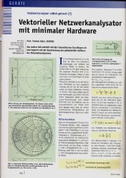
<strong>DG8SAQ</strong> <strong>VNWA</strong> <strong>Tutorial</strong>Experiments with the <strong>DG8SAQ</strong> <strong>VNWA</strong>and the <strong>SDR</strong>-<strong>Kits</strong> Test BoardTom BAIER<strong>DG8SAQ</strong>This is an excerpt from my Ham Radio 2013 presentation which hasbeen slightly extended (slides 6, 20 and 21 added).http://www.sdr-kits.net/ 1
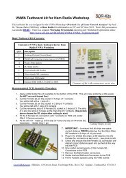
Test Board for HF ExperimentsCalibrationStandards:Open = n.c.Short:Load =47Ω:Thru:http://www.sdr-kits.net/ 2
Measuring „Load“-Resistor without SOL-Calibration?Works, because<strong>VNWA</strong> TX and RXport impedancesare exactly 50 Ω.Z x = 47 Ω yield ≈3,4 dBinsertion loss.‣ only Thrucalibrationrequired!http://www.sdr-kits.net/ 3
Measuring „Load“-Resistor in Transmission(=S 21 -Measurement)Only Thru calibrationrequiredMeasurement:Resistor betweenTX and RXhttp://www.sdr-kits.net/ 4
Measuring „Load“-ResistorResult = 46,6 Ωinductive partAnalysis with Custom Tracentamissioon datnvert transma to re eflectioCondatahttp://www.sdr-kits.net/ 5
SReflection Data vs. Transmission Data11normalizedimpedance:!Z xz 50S s 2( t S)z 121 11 Sz 121S t2( s S )11 212z 2These conversions can be performed with <strong>VNWA</strong> Custom traces.http://www.sdr-kits.net/ 6
Simple Calibration Standard Model:Only measured Load-Resistancehttp://www.sdr-kits.net/ 7
SOL-Calibration for S 11 -MeasurementTXShort Open Loadhttp://www.sdr-kits.net/ 8
Reflexion Measurement (S 11 ) of a1 nF Capacitor|S 11 |CcapacitiveESR = lossResonancedue tocomponentwiresCapacitor reflects almost total power, |S 11 | ≈ 0 dBhttp://www.sdr-kits.net/ 9
Modelling of Measurement Result in <strong>VNWA</strong>using Custom-TraceImpedance to Reflecion coefficienti 0,984 nF 9,3 nH 0,22 Ωeinfaches Modellhttp://www.sdr-kits.net/ 10
The Model is quite accurate!ktive ! Indukhttp://www.sdr-kits.net/ 11
Two Port Measurement of a 12 kHz BandPass Filter• S-Parameters applicable to lowfrequencies as well.• The <strong>VNWA</strong> too!http://www.sdr-kits.net/ 12
Special <strong>VNWA</strong> Settings for low FrequenciesLowest sample rate 300 Hz→ Nyquist limit 150 Hz→ Measurements down to≈150 Hz possibleIF must be within Codecfrequency range(20 Hz…16kHz)http://www.sdr-kits.net/ 13
SOLT-Calibration for 2-Port MeasurementsTXTXRXShort Open Load Thruhttp://www.sdr-kits.net/ 14
Beware: Steep Skirt Filters require Time tosettle to changing Stimulus!5 s sweep time0,3 s sweep timehttp://www.sdr-kits.net/ 15
Two Port Measurement of a 12 kHz BandPass FilterWe need to measure all four S-parameters(S 11 , S 21 , S 12 , S 22 )…http://www.sdr-kits.net/ 16
Two Port Measurement of a 12 kHz BandPass Filter: Forward MeasurementTX12RXS 11 , S 21 measuredhttp://www.sdr-kits.net/ 17
Two Port Measurement of a 12 kHz BandPass Filter: Reverse MeasurementTX21S 12 , S 22 measuredRXhttp://www.sdr-kits.net/ 18
What are measured 2-Port S-Parametersgood for?Optimum Match?http://www.sdr-kits.net/ 19
<strong>VNWA</strong> Matching Tool (1)Allows to recalculate 2-portS-parameters to source andload impedances differentfrom 50 Ohms!http://www.sdr-kits.net/ 20
<strong>VNWA</strong> Matching Tool (2)Complex conjugate ofsource impedance=filter input impedanceComplex conjugate ofload impedance=filter output impedancehttp://www.sdr-kits.net/ 21
Matching Analysis with <strong>VNWA</strong> Matching ToolOptimum: Z in = Z out = 610 Ωhttp://www.sdr-kits.net/ 22
Forced Impedance Match using Resistors50 Ω + 560 Ω = 610 Ωhttp://www.sdr-kits.net/ 23
Match works except for increased LossSimulated withMatching Tool≈ 21.8 dBMeasured withresistive matchhttp://www.sdr-kits.net/ 24
Effect of two 560 Ω Resistors in Signal Path:<strong>VNWA</strong> Complex Calculator21,7 dB additional attenuation http://www.sdr-kits.net/ 25
This can also be „properly“ simulated!Simulation Tool QUCS• http://qucs.sourceforge.net/t/• Universal circuit simulator• Free• No restrictions• Easy to use• Grafics and data export needsbrush uphttp://www.sdr-kits.net/ 26
Measured S-Parameters in QUCSmeasuredS-parametersfrom s2p-filehttp://www.sdr-kits.net/ 27
Matching Simulation in QUCSStandard diagrammoutput a bit strange→ Export simulation resultto <strong>VNWA</strong>http://www.sdr-kits.net/ 28
Comparison QUCS-Simulation vs.Measurementsimulatedmeasuerd withwith QUCS<strong>VNWA</strong>PERFECT!http://www.sdr-kits.net/ 29
Free Filter Design Software (1):Elsie – for LC-Filters• http://tonnesoftware.com/elsiedownload.html• LC-Filter Designer and Analyzer• Student version restricted to 7 dipols• Numerical simulation results export easily tos2p-file!http://www.sdr-kits.net/ 30
Free Filter Design Software (2):Dishal – for Crystal Filters• http://www.bartelsos.de/dk7jb.php/quarzfilter-horst-dj6ev• Crystal filter designer and analyzer• Simulates without crystal losses• S 21 -simulation results can be exportedhttp://www.sdr-kits.net/ 31
Free Filter Design Software (3):AADE Filter Design - for all filters• http://aade.com/filter32/download.htm• Univeral filter designer and analyzer• Free, but with nag screen• Easy to use• Numerical simulation results cannot beexportedhttp://www.sdr-kits.net/ 32
Design 3 Pole Butterworth π-Band Passfor 5 MHz with 3 MHz Bandwidth at 50 ΩFilter Design with Elsiehttp://www.sdr-kits.net/ 33
Elsie Simulation Resulthttp://www.sdr-kits.net/ 34
Modify Components to standard Values andfinite Q …simulation with finite Qhttp://www.sdr-kits.net/ 35
…and export Simulation into s2p-file forComparison with Measurement.Exporthttp://www.sdr-kits.net/ 36
Filter Hardwarehttp://www.sdr-kits.net/ 37
ComparisonMeasurement vs. Elsie SimulationS 21 , S 11 measured - Plot1, Plot2 Elsie simulatione ofuctorlelnancesinduparalresonseriehttp://www.sdr-kits.net/ 38
Measuring / Selecting Crystals:<strong>VNWA</strong> Crystal Analyzereg e.g. transmission(S21-measurement)Thru standarddhttp://www.sdr-kits.net/ 39
The <strong>VNWA</strong> Crystal Analyzer Tool:Find 3 similar Crystals…http://www.sdr-kits.net/ 40
With these we want to build a Crystal Filter→ Enter Crystal Parameters into AADEDaten vom<strong>VNWA</strong>CrystalAnalyzerübertraagenhttp://www.sdr-kits.net/ 41
AADE Minimum Loss (Cohn) Design186 Ω 66 pF 66 pF66 pF 66 pF186 Ωhttp://www.sdr-kits.net/ 42
Simulation in QUCS at 50 Ω using standardComponent ValuesCrystals simulated withs1p-file obtained by <strong>VNWA</strong>measurement!http://www.sdr-kits.net/ 43
Crystal Filter Hardwarehttp://www.sdr-kits.net/ 44
Crystal Filter:Measurement vs. Simulation at 50 ΩS 21 , S 11 measurement- Plot1, Plot2 QUCS simulationhttp://www.sdr-kits.net/ 45
Crystal Filter:Measurement vs. Simulation at 186 ΩS 21 , S 11 measurement- Plot1, Plot2 QUCS simulationhttp://www.sdr-kits.net/ 46
Now, we are able to…• Measure components• Design filters• Simulate filters• Measure filtersTry it foryourself!http://www.sdr-kits.net/ 47