USB-Synthesizer - SDR-Kits
USB-Synthesizer - SDR-Kits
USB-Synthesizer - SDR-Kits
- No tags were found...

You also want an ePaper? Increase the reach of your titles
YUMPU automatically turns print PDFs into web optimized ePapers that Google loves.
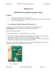
<strong>SDR</strong>-<strong>Kits</strong>.net QRP2000 <strong>USB</strong>-Controlled <strong>Synthesizer</strong> Kit Assembly v2.03c1. INTRODUCTION<strong>SDR</strong>-<strong>Kits</strong>.netQRP2000 <strong>USB</strong>-Controlled <strong>Synthesizer</strong>These instructions are applicable to Printed Circuit Boards V2.03 and V2.04 supplied by <strong>SDR</strong>-<strong>Kits</strong> after 24th October 2008.1. This easy to build project can generate almost any frequency between 3.5MHz and over 200MHz (160 MHz guaranteed for CMOS) with a resolution of less than 1 Hertz using the SiliconLabs Si570 Programmable Crystal Controlled Oscillator device. An Atmel ATTiny 45 orAtmel ATTiny 85 Micro controller interfaces the Si570 via the I2C bus to the <strong>USB</strong> bus to aPersonal Computer. The frequency of the Si570 can be set using popular <strong>SDR</strong> Applicationslike Power<strong>SDR</strong>, Winrad, Rocky or a standalone program Si570 <strong>USB</strong> Control. To use the kitthe LibUsb0 driver needs to be installed on the Computer in questions. This driver has beentested with Windows XP, ME, 2000, 98 and Vista home edition. The kit cannot be used withVista 64 and may not be possible under Linux.Contents:2. Bill of Materials3. Kit Assembly and hardware troubleshooting4. Driver Installation for Microsoft Windows Vista and Windows XP5. Driver installation verification6. Functional Tests7. Interfacing with Softrock RXTX 6.1 and 6.28 Power<strong>SDR</strong> Application Setup9 Rocky <strong>SDR</strong> Application Setup10 <strong>USB</strong>_SYNTH Application and SI570 CalibrationMain Applications:• Full Band or Multi Band coverage of Softrock RXTX V6.1 and V6.2 Transceiver. Soft66RFReceiver as well as other home brew Receivers, Transmitters and Transceivers• External Local Oscillator for other <strong>SDR</strong> hardware Projects – using SI570 <strong>USB</strong> Control• Wide range oscillator – output frequency programmable in steps < 1 Hz.• External /PTT output for keying other Transmitter projects/Basic Specification:• Frequency Range 3.5 MHz to about 200 MHz (10MHz to 160 MHz guaranteed by SiLab)• Stability +/- 50 ppm CMOS or +/0 20 ppm LVDS version – Jitter < 0.4 ps<strong>SDR</strong>-<strong>Kits</strong>.net © 2008 & 2009 by QRP2000 Design Page 1 of 28
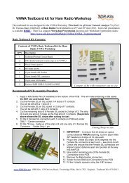
<strong>SDR</strong>-<strong>Kits</strong>.net QRP2000 <strong>USB</strong>-Controlled <strong>Synthesizer</strong> Kit Assembly v2.03cPlease note: T1 is optional 4:1 transformer for matching Si570 Output to 50 Ohms load.Parts for T1 (43BN2402 core and 60cm #35AWG wire are only supplied with Kit 2 with theSi570BBC000141DG LVDS device.( ) Inventory of Kit parts is highly recommended – see example Fig 1 below.Caution: Please observe antistatic precautions for semiconductor devicesDo not remove Si570 device from anti-static bag until neededNote: If you have a question about the kit. please contact Jan G0BBL via sdrkits @ gmail.com(remove all spaces in email address)Fig 1 Example Inventory of Kit Parts – (photo by Steve G0XAR)3. KIT ASSEMBLYIntroduction:Assembling this kit will involve soldering of surface mount components. This is not difficult but somecare and patience is needed. You will need a well lit and clear work surface, a suitable soldering ironwith a small tip, some fine (for example 24swg – 0.5mm) resin cored solder and a pair of long<strong>SDR</strong>-<strong>Kits</strong>.net © 2008 & 2009 by QRP2000 Design Page 3 of 28
<strong>SDR</strong>-<strong>Kits</strong>.net QRP2000 <strong>USB</strong>-Controlled <strong>Synthesizer</strong> Kit Assembly v2.03ctweezers, The type of tweezers should allow you to hold the component GENTLY, otherwise the yourtweezers may act as a rocket launcher for tiny SMD parts!!. Firstly make sure that the PCB is heldsecurely to the work surface so it does not move around. Using "Blue Tack" on the edges of the boardis one way of doing this. Then identify the pair of lands on the pcb that the surface mount componentwill be soldered to. Melt a small blob of solder on to one of the lands as a coat. Then, using thetweezers, pick up the the surface mount component and place it across the lands and melt the solder onthe pre soldered land. This should effectively hold the component in place whilst you solder it to theunsoldered land. Then resolder it to the to the first land. Then check that the joints are good using amagnifying glass. This all sounds very complicated but it works in practice. If this is your first timeusing SMD you may wish to find a junk computer card and practice on it first. There are also anumber of excellent tutorials on the internet - and no you do not need an oven or an SMworkstation. An ordinary soldering iron (preferably temperature controlled is good enough.Good luck!!Bottom PC mounted componentsFig 2 PCB with all components except Si570 fitted at bottom of boardPlease note: All Capacitors are 0.1uF except C4 which is 1nF. LK is Wirelink( ) Remove any components from PCB so PCB is bare( ) Check Kit contents against Bill of Materials (Parts for T1 are only supplied in Kit 2)( ) Place PCB upside down as in fig 2.<strong>SDR</strong>-<strong>Kits</strong>.net © 2008 & 2009 by QRP2000 Design Page 4 of 28
<strong>SDR</strong>-<strong>Kits</strong>.net QRP2000 <strong>USB</strong>-Controlled <strong>Synthesizer</strong> Kit Assembly v2.03c( ) Look at Figure 2 to see the exact placement of the SMD capacitors and the PCB terminals.The SMD Capacitors are the small oblong shapes (0805 package), the soldered ends of thePCB terminals show as shiny circles.( ) Adjust Temperature of Temperature Controlled Soldering Station to correct temperature forsoldering SMD components. Temperature depends on type of solder you are using normally330C or 630F with 60/40 Pb/Sn( ) Solder SMD 0.1uF 0805 Capacitors C2, C3, C5, C6, C7, C8, C9, C11, C12, C13 and C14 asshown in Figure 2. Then check against Figure 2.( ) Solder C4 1nF 0805 Capacitor (identified with BLACK mark on strip) next to C3 (Lowerright hand side of the board( ) Check all joints – the board should look like fig 2 below( ) Note: 6 PCB pins are supplied, If you are using the kit for other purposes then solder PCB pinsto suit your particular application( ) Fit PCB terminals by pressing pin through PCB using a hard metal surface or long nose pliersmaking sure that you do NOT damage any of the SMD capacitors in the process and solder atBottom layer . Typical location of the PCB terminals is: +12V, +5V, GND, CW1, CW2 andPTT as shown in Fig 3 below.( ) Turn board overComponents mounted on Top ~Layer of PCB (Top Silk)<strong>SDR</strong>-<strong>Kits</strong>.net © 2008 & 2009 by QRP2000 Design Page 5 of 28
<strong>SDR</strong>-<strong>Kits</strong>.net QRP2000 <strong>USB</strong>-Controlled <strong>Synthesizer</strong> Kit Assembly v2.03cFig 3 Component lay-out diagramPlease note that “KEYUP” and “OVEN” are not used – Optional ConnectionsPlace the board so you can see the components side with the placement (silk screen) diagram in view.Orient the board so that the words “<strong>USB</strong> SYNTHESIZER” is at the top.( ) 8 pin IC socket for U1 ensuring that the indentation on the end of the socket matches that onthe silk screen( ) <strong>USB</strong> Socket – solder pins including the ground connections.( ) Mount Diodes D1, D2 D3, D4, D5 and D6Note: observe cathode band and solder observing the polarity of the diode.For D1, D4, D5 and D6 the white band should point toward the hole marked “k”For D2 and D3 the black band should be facing the holes marked “k” next to <strong>USB</strong> socket J1..( ) Mount Resistors R1 and R2 (68 Ohm blue grey black gold brown).Mount R3 (2K2 red red black brown brown).R4 (1M brown black black yellow brown).Mount Resistor R9 = 220 Ohm (red red black black)Mount R5, R6, R7, R8, R10, R11 and R12 (4K7 yellow violet black brown brown)<strong>SDR</strong>-<strong>Kits</strong>.net © 2008 & 2009 by QRP2000 Design Page 6 of 28
<strong>SDR</strong>-<strong>Kits</strong>.net QRP2000 <strong>USB</strong>-Controlled <strong>Synthesizer</strong> Kit Assembly v2.03c( ) Remove Power to PCB( ) Caution: observe anti-static precautions handling semiconductor( ) Plug ATTiny45 or ATTiny 85 IC holder for U1 – pin 1 should be aligned towards U3 on thetop silk( ) Connect <strong>USB</strong> <strong>Synthesizer</strong> to <strong>USB</strong> socket of a Personal Computer and measure voltagebetween U1 Pin 8. Reading should be around 4.3V DC( ) Disconnect <strong>USB</strong> cable from <strong>USB</strong> <strong>Synthesizer</strong>Final assembly of Si570 Device( ) Caution: observe antistatic precautions handling semiconductors( ) The Si570 device is soldered on the bottom of the PCB( ) Locate the Dot on the Si570 device and align with pin 1 marked on the PCB and solder.The Dot is located on the left hand side of bottom line showing the Batchnumber.Fig 4Location of S570 chip – Bottom left pin is Pin 1 aligned with dot on Si571<strong>SDR</strong>-<strong>Kits</strong>.net © 2008 & 2009 by QRP2000 Design Page 8 of 28
<strong>SDR</strong>-<strong>Kits</strong>.net QRP2000 <strong>USB</strong>-Controlled <strong>Synthesizer</strong> Kit Assembly v2.03cFinal Test and commissioning( ) Remove Jumper JP1 from J1 which is located next to Diode D6( ) Connect PCB to a 5-12V DC Power Supply and measure Current Consumption typicallyshould be around 70-85mA( ) Remove External Powersupply.( ) Set Jumper JP1 to connect J1 Pin 1 and Pin 2 (<strong>USB</strong> Powered)( ) If Optional Output Transformer T1 is fitted with Kit 1 Si570 CMOS device solder linkbetween P1 Pin 2 and P1 Pin 3. Remove X2 and Y1 from GND. Twist the X2 and U1 andsolder together and leave floating. See Fig 12 Ckt diagram on Page 28.Photo of completed PCB (top)<strong>SDR</strong>-<strong>Kits</strong>.net © 2008 & 2009 by QRP2000 Design Page 9 of 28
<strong>SDR</strong>-<strong>Kits</strong>.net QRP2000 <strong>USB</strong>-Controlled <strong>Synthesizer</strong> Kit Assembly v2.03c3.1 HARDWARE TROUBLE SHOOTINGBefore you can use the synthesizer board, you need to perform Driver Installation as described inChapter 4. Provided the Driver is installed the following DC voltages should be measured on anormal working <strong>USB</strong>- <strong>Synthesizer</strong> Kit:U1 ATTiny45 or ATTiny85Pin 1 +4.3V +/- 10% Pin 1 Not connectedPin 2 +3.3V (no I2C activity) Pin 2 +3.3VPin 3 +0.1V (PTT off) +4.3V (PTT on) Pin 3 0V GNDU2 Si570 DevicePin 4 0V GND Pin 4 (CMOS: 2.7V pkpk RF) (LVDS: 0.7V pkpk RF)Pin 5 0.1V DC (idle <strong>USB</strong> bus) Pin 5 (CMOS = NC) LVDS: 0.7V pkpk RF out)Pin 6 +3.3V (no I2C activity) Pin 6 +3.3V VDDPin 7 +2.5V to +2.7V(idle <strong>USB</strong> bus) Pin 7 +3.3V (no I2C activity)Pin 8 +4.3V +/- 10% VDD Pin 8 +3.3V (no I2C activity)CW Key 1 Key-up 4.3V DC Key-down 0V CW Key 2 Key-up 4.3V DC Key-down 0VThe most likely problem is “<strong>USB</strong> enumeration failure” The <strong>USB</strong> synthesizer is not recognized bythe Computer. Tom Baier DG8SAQ has written a paper to help you check this type of failure.Click HERE to investigate <strong>USB</strong>-Enumeration failures<strong>SDR</strong>-<strong>Kits</strong>.net © 2008 & 2009 by QRP2000 Design Page 11 of 28
<strong>SDR</strong>-<strong>Kits</strong>.net QRP2000 <strong>USB</strong>-Controlled <strong>Synthesizer</strong> Kit Assembly v2.03c4. DRIVER INSTALLATION PROCEDUREIntroduction: Before you can use the Kit you must install a DRIVER on each Computer to which the<strong>USB</strong>-<strong>Synthesizer</strong> board will be connected to. The Drivers for the <strong>USB</strong>-<strong>Synthesizer</strong> kit are successfullyused with the following Operating systems: Windows XP, ME, 2000, 98 and Vista home edition.There are some reports of successfully operation under Linux, however operation under VISTA 64 isnot possible as this operating system only allows for installation of Digitally Signed Drivers.4.1 For Microsoft VISTA home edition a separate Vista Driver Installation Document isavailable here, courtesy of Steve Farthing, G0XAR.4.2 Driver Installation Procedure for Microsoft XP Operating System.• Download Si570_Firmware from: http://www.mydarc.de/dg8saq/SI570/index.shtml• Press “Save target as”• Unzip the file SI570_firmware.zipThe following directories will be created<strong>SDR</strong>-<strong>Kits</strong>.net © 2008 & 2009 by QRP2000 Design Page 12 of 28
<strong>SDR</strong>-<strong>Kits</strong>.net QRP2000 <strong>USB</strong>-Controlled <strong>Synthesizer</strong> Kit Assembly v2.03c• Select “No, not this time”• Press “NEXT”The following screen should now be displayed:Deselect “Install the software automatically”<strong>SDR</strong>-<strong>Kits</strong>.net © 2008 & 2009 by QRP2000 Design Page 14 of 28
<strong>SDR</strong>-<strong>Kits</strong>.net QRP2000 <strong>USB</strong>-Controlled <strong>Synthesizer</strong> Kit Assembly v2.03cSelect “install from a list or specific location”Press “Next>”The following screen is displayed• Deselect “Search removable Media”• Select “Include this location in the search”• Press “Browse”• Select Folder AVR-<strong>USB</strong>-Driver as shown below<strong>SDR</strong>-<strong>Kits</strong>.net © 2008 & 2009 by QRP2000 Design Page 15 of 28
<strong>SDR</strong>-<strong>Kits</strong>.net QRP2000 <strong>USB</strong>-Controlled <strong>Synthesizer</strong> Kit Assembly v2.03c• Click “Ok”• Press “Next>”• Software is being installedWhen successfully installed, following message displayed:<strong>SDR</strong>-<strong>Kits</strong>.net © 2008 & 2009 by QRP2000 Design Page 16 of 28
<strong>SDR</strong>-<strong>Kits</strong>.net QRP2000 <strong>USB</strong>-Controlled <strong>Synthesizer</strong> Kit Assembly v2.03cClick “Finish”Message displayed “Found New hardware successfully installed”END OF DRIVER INSTALLATION PROCEDURE5. DRIVER INSTALLATION VERIFICATIONA check can be made at any time if the driver is properly installed but only if the<strong>USB</strong>-module is plugged in• Press “START”• Press “Control Panel”• Select “System”Following Screen is displayed• Select “Hardware”• Select “Device Manager”A folder “Lib<strong>USB</strong>-Win32 Devices” should be displayed(only when <strong>USB</strong>-<strong>Synthesizer</strong> is Plugged-in)• Press to Expand AVR-<strong>USB</strong> Device folder<strong>SDR</strong>-<strong>Kits</strong>.net © 2008 & 2009 by QRP2000 Design Page 17 of 28
<strong>SDR</strong>-<strong>Kits</strong>.net QRP2000 <strong>USB</strong>-Controlled <strong>Synthesizer</strong> Kit Assembly v2.03cClick on “AVR <strong>USB</strong> Device”Proper operation of the Driver may now be checked• Select tab “Driver”The screen below is displayed and options made available to• Remove Driver• Update Driver• Reinstall Driver<strong>SDR</strong>-<strong>Kits</strong>.net © 2008 & 2009 by QRP2000 Design Page 18 of 28
<strong>SDR</strong>-<strong>Kits</strong>.net QRP2000 <strong>USB</strong>-Controlled <strong>Synthesizer</strong> Kit Assembly v2.03cEND OF DRIVER INSTALLATION VERIFICATION6. FUNCTIONAL TESTSOnce driver is installed the <strong>USB</strong> <strong>Synthesizer</strong> board can be tested with the applicationSi570_<strong>USB</strong>_ Test which can be found in the folder 'hostware” which is found in the “Si570 folder”containing the Driver.Start “Si570_<strong>USB</strong>_Test”Check SI570 i2c adr is set as follows LVDS Si570BBC000141DG i2c address = 55 Hex CMOS Si570CAC000141DG i2c address = 55 HexNote: the address is 55 Hex is valid for all Si570 devices supplied by <strong>SDR</strong>-<strong>Kits</strong>.net.The address may be different for Si570 devices obtained from other sources.Click button “Test<strong>USB</strong>”The following screen should be shown.<strong>SDR</strong>-<strong>Kits</strong>.net © 2008 & 2009 by QRP2000 Design Page 19 of 28
<strong>SDR</strong>-<strong>Kits</strong>.net QRP2000 <strong>USB</strong>-Controlled <strong>Synthesizer</strong> Kit Assembly v2.03cSetting Frequency:Enter the desired frequency in the Window MHz Example frequency entered 16.400 MHz click “set freq by value” click “read SI570 registers”Following screen should be displayed<strong>SDR</strong>-<strong>Kits</strong>.net © 2008 & 2009 by QRP2000 Design Page 20 of 28
<strong>SDR</strong>-<strong>Kits</strong>.net QRP2000 <strong>USB</strong>-Controlled <strong>Synthesizer</strong> Kit Assembly v2.03cEND OF FUNCTIONAL TEST PROCEDURE7. INTERFACING TO SOFTROCK RXTX V6.1 or V6.2 TRANSCEIVERThree connections are required to connect the <strong>USB</strong>-<strong>Synthesizer</strong> to the RXTX V6.x transceiver asfollows:( ) Prepare a 10cm (4 inch) length of RG174 miniature coaxial cable by removing 1 cm plastic ateither end of the cable. Next remove 3mm insulation from the inner conductor at both ends.Fig 5: Preparation of 10cm 4 inch Coaxial cable( ) On RXTX PCB, disable the Crystal Oscillator by removing 2 pin Jumper from JP2.( ) On RXTX PCB remove 2 pin Jumper from JP1.( ) Solder Inner conductor of coaxial cable to JP1 pin 2 as shown in fig 5 below:<strong>SDR</strong>-<strong>Kits</strong>.net © 2008 & 2009 by QRP2000 Design Page 21 of 28
<strong>SDR</strong>-<strong>Kits</strong>.net QRP2000 <strong>USB</strong>-Controlled <strong>Synthesizer</strong> Kit Assembly v2.03c( ) Solder Outer conductor of coaxial cable to JP1 pin 4 (Ground) as shown below.Fig 6: Connection of Coaxial Cable to RXTX PCB JP1( ) On <strong>USB</strong> <strong>Synthesizer</strong> board solder inner conductor of coax cable to pin A( ) Solder outer braid of coax cable to centre pin B( ) Connect wire from +12V terminal to +12VDC terminal of RXTX PCB( ) Connect wire from <strong>USB</strong>-<strong>Synthesizer</strong> “PTT” to RXTX PCB “PTT_IN”www.<strong>SDR</strong>-kits.net+12VfromRXTXTo PTT_In onRXTX PCBA: Inner CoaxB: outer braidFig 7: Connections on <strong>USB</strong>-<strong>Synthesizer</strong> PCB to support Softrock RXTX<strong>SDR</strong>-<strong>Kits</strong>.net © 2008 & 2009 by QRP2000 Design Page 22 of 28
<strong>SDR</strong>-<strong>Kits</strong>.net QRP2000 <strong>USB</strong>-Controlled <strong>Synthesizer</strong> Kit Assembly v2.03c8 POWER<strong>SDR</strong> SETUP FOR RXTX <strong>USB</strong> SUPPORT (updated 16 th April 2009)( ) Download Power<strong>SDR</strong> application from Flexradio Systems:Click here which version are currently available for download. Versions recently testedinclude 1.16.1.exe 1.14.0.exe and 1.12.1.exe( ) Download and install the required version of Power<strong>SDR</strong>.exeWe now need to download and install the file Sdr1kUsb.dll (written by Guido PE1NNZ withcooperation from Alan M0PUB) which allows Power<strong>SDR</strong> to communicate with <strong>USB</strong>-<strong>Synthesizer</strong> board through the driver.( ) Download the file Sdr1kUsb.dll from Sourceforge repository and save this file in the samedirectory where you installed Power<strong>SDR</strong> in the previous step. (for Power<strong>SDR</strong> 1.16.1.typically in C:\Program Files\FlexRadio Systems\Power<strong>SDR</strong> v1.16.1( ) Plug-in <strong>USB</strong>-<strong>Synthesizer</strong> board with Jumper JP1 set. The board should berecognized. Start Power<strong>SDR</strong>.exe application and open tab “Hardware Config” and tickthe box “<strong>USB</strong> Adapter” as shown in fig 8 below. Click “Apply”and “Ok”Fig 8: Power<strong>SDR</strong> <strong>USB</strong> setup ScreenNote: Your existing CW keying arrangements (Parallel port or Serial port) as documented in thePower<strong>SDR</strong> documentation continues to be supported. The use of the <strong>USB</strong>-<strong>Synthesizer</strong> - Straight CWKey-input is optional.<strong>SDR</strong>-<strong>Kits</strong>.net © 2008 & 2009 by QRP2000 Design Page 23 of 28
<strong>SDR</strong>-<strong>Kits</strong>.net QRP2000 <strong>USB</strong>-Controlled <strong>Synthesizer</strong> Kit Assembly v2.03c• The frequency may be set to the nearest Hz. And a Multiplication factor or Frequency offset(IF offset) may be specified as shown in the setup screen below• “Last Frequency Remember” Option for Standalone applications.• Provision to Calibrate the SI570 to exact frequencyFig 10: Si570 <strong>USB</strong> controller <strong>USB</strong>_Synth.exeWhen the SETUP is selected the following screen will be displayed. This shows how the variousparameters which may be specified to suit your particular application:Fig 11: Si570 <strong>USB</strong> controller <strong>USB</strong>_Synth.exe Setup Screen<strong>SDR</strong>-<strong>Kits</strong>.net © 2008 & 2009 by QRP2000 Design Page 25 of 28
<strong>SDR</strong>-<strong>Kits</strong>.net QRP2000 <strong>USB</strong>-Controlled <strong>Synthesizer</strong> Kit Assembly v2.03c10.1 Si570 FREQUENCY CALIBRATIONCalibration of the Si570 may be easily done using the <strong>USB</strong>-Synth Application as follows( ) Set Jumper JP1 and connect <strong>USB</strong>-<strong>Synthesizer</strong> to <strong>USB</strong> Port( ) On Setup Screen press button “Calibrate to factory Standard start-up frequency”( ) The SI570 will generate the Standard start-up frequency specified for this device. (For Si570devices supplied by <strong>SDR</strong>-<strong>Kits</strong> this will be nominally 56.320000 MHz)( ) With accurately calibrated Frequency Counter measure the output frequency of the Si570.( ) Enter the frequency measured in the window “Factory Calibration Frequency” and pressbutton“Calibrate to factory Standard start-up frequency” to perform calibration.The calibration values are now stored in AVR EEPROM for future use.10.2 ALTERNATIVE CALIBRATION ROUTINE FOR WWV OR OTHER SOURCE( ) Tune Receiver to receive a accurate calibration source like WWV on 10.000 MHz.( ) Set Jumper JP1 and connect <strong>USB</strong>-<strong>Synthesizer</strong> to <strong>USB</strong> Port. Connect a short wire tothe <strong>USB</strong>_Synth output and couple the output signal to the Receiver until a BEAT frequencywith the calibration source is heard.( ) Operate the 'SHIFT CALIBRATION” buttons until the <strong>USB</strong>-Synth RF output is ZERO BEATwith the calibration source to complete calibration.This complete Calibration Routine.10.2 APPENDIX CALIBRATIONDefinitions:Fa = Actual Receive Frequency (Frequency of known Radio Station or Radio Signal published inFrequency list or measured )Ft = Frequency entered to receive the “known Radio Station”Fxo = Frequency of the Si570 internal Crystal used in calculate and set “Ft”Fxn = Corrected Frequency of the Si570 Internal Crystal to set “Ft” to the same frequency as “Fa”Formula to calculate Fxn = Fxo – (Ft – Fa) / Fa * Fxo<strong>SDR</strong>-<strong>Kits</strong>.net © 2008 & 2009 by QRP2000 Design Page 26 of 28
<strong>SDR</strong>-<strong>Kits</strong>.net QRP2000 <strong>USB</strong>-Controlled <strong>Synthesizer</strong> Kit Assembly v2.03cExample =Fxo = 114,300.500 kHzFa = 10,000.000 kHzFt = 9,995.355 kHz(WWV reception on 10 MHz)Frequency set to receive WWVFxn = 114,353.593 (Corrected Crystal frequency – whichshould be stored (in Hz) for future use bythe program)END OF DOCUMENTFig 12: <strong>USB</strong> <strong>Synthesizer</strong> Circuit Diagram PCB V2.03 and V2.04<strong>SDR</strong>-<strong>Kits</strong>.net © 2008 & 2009 by QRP2000 Design Page 27 of 28
<strong>SDR</strong>-<strong>Kits</strong>.net QRP2000 <strong>USB</strong>-Controlled <strong>Synthesizer</strong> Kit Assembly v2.03c<strong>SDR</strong>-<strong>Kits</strong>.net © 2008 & 2009 by QRP2000 Design Page 28 of 28