Kit Manual PAOKLT Si570 VFO FIRST ISSUE PCB - SDR-Kits
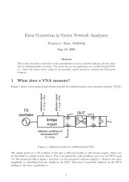
Kit Manual PAOKLT Si570 VFO FIRST ISSUE PCB - SDR-Kits
Kit Manual PAOKLT Si570 VFO FIRST ISSUE PCB - SDR-Kits
- No tags were found...

You also want an ePaper? Increase the reach of your titles
YUMPU automatically turns print PDFs into web optimized ePapers that Google loves.
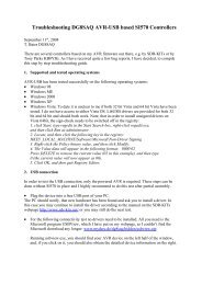
Ton Blokker PA0KLT <strong>PAOKLT</strong> LCD Synthesizer kit <strong>Manual</strong> issue V5.4 for SECOND <strong>ISSUE</strong> <strong>PCB</strong> Jan Verduyn G0BBL2. Brief Specification:• Standalone Low Noise <strong>VFO</strong> Synthesizer suitable as Signal Generator, Local Oscillator or<strong>VFO</strong> etc with good frequency stability for many (Amateur) Radio Projects.• <strong>Si570</strong> “Smooth Tuning” Algorithm - No interuption of rf output when <strong>Si570</strong> is tunedwithin +/- 3500 ppm of last Coarse Frequency command. 96 steps/rotation by firmware.• 32 Frequencies may be stored in Memory in two Memory Banks• Frequency coverage options depending on <strong>Si570</strong>/Si571 type fitted:◦ <strong>Si570</strong>CAC CMOS: 3.5MHz - 160 MHz at 3V pkpk Square wave CMOS Output (280MHz possible but not guaranteed)◦ <strong>Si570</strong>BBC LVDS: 3.5 MHz - 280 MHz at 0.7V pkpk LVDS level◦ <strong>Si570</strong>BBB LVDS: 3.5 MHz - 810 MHz at 0.7V pkpk LVDS level (Max 945 MHzpossible but not guaranteed)◦ <strong>Si570</strong>DBA CML: 3.5 MHz - 945 MHz, 970 MHz - 1134 MHz and 1213 MHz -1417.5 MHz at typically 1.5V pkpk CML level. (In PA0KLT <strong>Kit</strong> typically 3.5 MHz -1417 MHz continuous coverage is obtained in practice but not guaranteed)◦ Si571CFC CMOS: 3.5 MHz - 160 MHz with FM Modulation input. (typically 3.5MHz up to 210MHz is possible but not guaranteed) See fig 5. note 5.• Mode Offset applied: AM = 0 kHz, USB/LSB = +/- 1.5 kHz and CWU/CWL = +/- 750 Hz• Power Supply voltage: 8-12V or from single +5V supply with modification• Current consumption 125mA (20mA drawn by LCB backlight)• Provision of RF output transformer options on <strong>PCB</strong>◦ Homebrew BN43-2402 4:1 transformer up to 200 MHz (BN61-2402 core to 300 Mhz)◦ Minicircuits T-622 4:1 up to 200 MHz◦ Coilcraft WBC4-1WLB up to 800 MHz (fits on <strong>PCB</strong>)A Minicircuits ADT4-1WT 4:1 transformer 2 - 775 MHz may also be used by cuttingtracks on the <strong>PCB</strong>.• Support industry standard LCD display 2 x16 to 2x20 characters• LCD module supplied has built-in backlight - size 73mm x 36mm• <strong>PCB</strong> size: 70mm x 34mm - Tin plated screen box available.• Firmware written in Assembler and supports following features:◦ Programmable IF Offset, minimum and maximum frequency and SI570 I2C address◦ <strong>Si570</strong> Frequency calibration◦ Programmable multiplier x1. x2 x4 or x8• IF Offset is removed when "LOCK" is applied (TX Mode). See Table 3 and Table 4.• <strong>Kit</strong> suitable for constructors with some previous kit assembly experience. Somecomponents like capacitors (0805mm) and <strong>Si570</strong> are Surface Mount Devices. Ability tounderstand circuit diagrams is required if the kit is to fit your specific requirements.• Si571 chip is support from V4.19 Firmware onwards. (see fig 5 - notes)www.<strong>SDR</strong>-kits.net 2 of 21
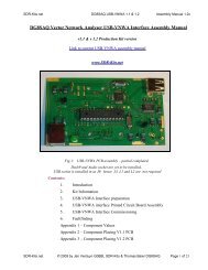
Ton Blokker PA0KLT <strong>PAOKLT</strong> LCD Synthesizer kit <strong>Manual</strong> issue V5.4 for SECOND <strong>ISSUE</strong> <strong>PCB</strong> Jan Verduyn G0BBL3. Bill of MaterialsThe following parts are supplied in the basic kit.Parts marked in blue are options as ordered by you.Pcs/kit Part Value Remarks1 C1 10uF Electrolytic Radial5 C2, C3, C4, C5 1uF Ceramic 0805 SMD Blue stripeC6, C7, C8, C9,8 C10, C11 100nF Ceramic 0805 SMD - No marking2 C12 1nF Ceramic 0805 SMD - Black Stripe3 R1, R3 4k7 0.25W yellow violet red gold1 RV1 4k7 adjustable1 R4 47 ohm 0.6W - LCD Backlight Yellow violet black gold brown1 D1 1N40011 U3 LF33ABV 3.3V LDO Regulator TO2201 U4 7805 5V Regulator TO2201 U1 ATMega8-16 or Mega88-20PU <strong>PAOKLT</strong> Firmware marked1 IC Socket 28 pin DIL for U1 28 pin1 P1 2 pin header plug (+8 - +12V) 0.1” male1 P2 3 pin header plug (HF Out) 0.1” male1 P3 LCD Header 14 pin IDC Male1 P4 Aux Conn Header 20 pin IDC Male1 J1 LCD Connector 14 pin IDC female1 J2 Aux Connector 20 pin IDC female1 <strong>PCB</strong> PA0KLT <strong>SDR</strong>-<strong>Kit</strong>s - marked E301751 (see fig 1)2 mini push switch Red (Mem and ESC)2 mini push switch Black (< and >)0.3 Ribbon cable 16 way1 Encoder Encoder 24 step contact1 LCD Display with backlight 16 character by 2 lines1 U2 option 1 <strong>Si570</strong>CAC000141DG 3.5-160 MHz - max 210 MHz - CMOS output1 U2 Option 2 <strong>Si570</strong>BBC000141DG 3.5-280 MHz - LVDS output1 U2 Option 3 <strong>Si570</strong>BBB000141DG 3.5-810 MHz - Max 940 MHz - LVDS output1 T1 Option 1 43 BN-2402 kit with 32AWG = 0.23mm enamelled wire1 T1 Option 2 Coilcraft ADT4-1WT 4:1 wound transformerCaution - This <strong>Manual</strong> is applicable to <strong>Kit</strong>s supplied up to May 31st 2010 with <strong>PCB</strong> marking E301751 orhigher batch numbersIf the <strong>PCB</strong> supplied has V238031 printed on the track side then you have a <strong>FIRST</strong> <strong>ISSUE</strong> <strong>PCB</strong>and this manual is NOT applicable Please download <strong>PAOKLT</strong> Assembly and OperationsMANUAL for <strong>FIRST</strong> <strong>ISSUE</strong> <strong>PCB</strong>.www.<strong>SDR</strong>-kits.net 3 of 21
Ton Blokker PA0KLT <strong>PAOKLT</strong> LCD Synthesizer kit <strong>Manual</strong> issue V5.4 for SECOND <strong>ISSUE</strong> <strong>PCB</strong> Jan Verduyn G0BBL4. <strong>PCB</strong> Assembly instructionsAssembly of the <strong>PCB</strong> should be quite straight forward. Observe antistatic precautions especiallywhen handling Semiconductors - <strong>Si570</strong> and the programmed AVR. The <strong>Kit</strong> assembly sequency isas follows:• Assemble the <strong>PCB</strong> and check voltages on regulators• Wire up LCD Display unit and Aux Connections to 4 push buttons• Install AVR in socket• Apply Power and check AVR and LCD functionality• Solder in <strong>Si570</strong> XO Synthesizer chip and test RF outputUse a 15-40W Solder station or a 15W - 25W soldering iron and 0.5mm solder. SMD soldering isnot difficult - Apply a little tin to one of the pads, place the SMD capacitor over the pads and applyheat to make the bo.d. Once the SMD part has been soldered to one of the pads continue bysoldering the second pad and finish off by reflowing the tin on the first pad, applying a little moretin if necessary. Use a magnifiying glass to inspect any joints.Caution: Do NOT solder U2 = <strong>Si570</strong> until instructed to do so.( ) Start by fitting the 1uf Ceramic 0805 capacitors C2, C3, C4 and C5 (blue stripe)as shown in fig 2. (there is no polarity indication as capacitors are bipolar)( ) Solder 100nF 0805 capacitors (no markings) C6, C7, C8, C9, C10 and C11( ) Solder C12 = 1nF - black stripe( ) Solder R1, R2 and R3 = 4k7 resistors (yellow violet red gold)( ) Fit and solder RV1 4k7 Preset( ) Fit diode D1 1N4001 - observe white band and solder( ) Fit C1 10uF - observe correct polarity. White stripe is negative - lead.( ) Fit 28 pin DIL socket - Observe notch and align as shown on <strong>PCB</strong>.Ensure that the socket is mounted flush to the board solder pin one and pin 28 thencheck for a snug fit to the board. If it is not apply a slight pressure to the DILsocket and re-solder the pins. Once it is flush solder the remaining pins( ) Fit connectors P1 (location 8-12V) and P2 (location HF Out) makingsure that the short pins are the ones you solder to the board.( ) Refer to fig. and fit connectors P3 (14 pin LCD header) and P4 (20 pin AUXConnector).Caution - ensure that the notch of the connector is located shown in Fig 1Ensure that the connectors are fitted flush with the board. Use the sameprocedure as you did with the 28 pin DIL socket to ensure that theconnectors are fitted flush with the board.www.<strong>SDR</strong>-kits.net 4 of 21
Ton Blokker PA0KLT <strong>PAOKLT</strong> LCD Synthesizer kit <strong>Manual</strong> issue V5.4 for SECOND <strong>ISSUE</strong> <strong>PCB</strong> Jan Verduyn G0BBL( ) Fit TO220 Regulators U3 (LF33) and U4 (7805) and check position against <strong>PCB</strong>before soldering.Inital <strong>PCB</strong> testingAt this stage all components except the AVR and SI570 are fitted on the <strong>PCB</strong>.( ) Connect +8V - 12V DC Power to P1 on the <strong>PCB</strong> - observe polarity. Currentconsumption should be no more than 20mA at this stage. Switch of and investigateif current is too high or if any components are getting hot or any of the voltages arenot within +/- 5% of the expected valued.( ) Use a DC voltmeter to check whether +5V is present on the "IN" of U3 LF33.and +3.3V is present on the output pin of U3 - LF33 regulator before proceeding.( ) Switch off Power and remove leads from P1.Final AssemblyCAUTION: In the following step ensure the 14 Way cable is connectedcorrectly so pin 1 of LCD is connected to GND and Pin 2 to +5V otherwise theLCD display will be destroyed.( ) LCD Connector J1: In this step the wiring to the LCD display.Before cutting to length you will wish to consider how long the cable needs to be tofit in the enclosure you are going to use.Cut a length of 16 way ribbon cable required to connect between <strong>PCB</strong> and LCDmodule. Peel off two of the cores at the opposite end to the red cores to reduce thecable to 14 wires. Fit the cable at right angle into the IDC connector so the redcoloured wire connects to P3 Pin 1 (See fig 2). Clamp into a small vice. Turn thevice until the ribbon cable is solidly pressed into the connector.Caution: Over-tightening may damage the connector.( ) Remove a 2mm insulation from the end of each of the wires. Refer to Fig 6. andSolder the 14 wires to the LCD module. Observe connections as shown in fig 5. (J1pin 1 connects to LCD pin 1, J2 pin 2 to LCD pin 2 etc)( ) LCD Backlight connections J1: Caution - the following instructions are onlyvalid for LCD modules supplied by <strong>SDR</strong>-<strong>Kit</strong>s: Use the two wires removedpreviously and solder one wire from LCD Pin 1 to LCD Pin 16. Solder one end ofthe 47 Ohm resistor to LCD module pin 15 and the other end of the resistor to Pin 2of the LCD module. (This is shown in fig 6.)( ) AUX Connector J2: Fit the required length of 16 way ribbon cable on the 20 Wayconnector J2 similarly to how you prepared the cable for the LCD module. Cautionwww.<strong>SDR</strong>-kits.net 5 of 21
Ton Blokker PA0KLT <strong>PAOKLT</strong> LCD Synthesizer kit <strong>Manual</strong> issue V5.4 for SECOND <strong>ISSUE</strong> <strong>PCB</strong> Jan Verduyn G0BBLthe red coloured wire should connect to pin 1 of P4, Note: the correct orientationof the pins for J2 is shown in Fig 2. Pin 17-Pin 20 are reserved for futureuse.The table below shows the essential connections required to support thefour pushbuttons ( < > ESC and MEM) and the Rotary Encoder for Tuning.Wiring Aux Connector – J2 (mates with P4)Pin Description Remark1 Band Select Output A Optional use2 Band Select Output B Optional use3 Band Select Output C Optional use4 Band Select Output D Optional use5 < cursor pushbutton essential connection6 > cursor pushbutton essential connection7 Rotary Control “A” essential connection8 Rotary Control “B” essential connection9 AM Mode Select input Optional use10 +5V output Optional use11 GND essential connection12 ESC pushbutton essential connection13 MEM pushbutton essential connection14 SSB/CW Select input Optional use15 LSB/USB Select input Optional use16 LOCK input Optional use17 PB2 – D4 Future Use18 PB3 – D5 Future Use19 PB4 – D6 Future Use20 PB5 – D7 Future UseTable 1: Aux Connector J2( ) Rotary Encoder: The 24 step encoder (enhance to 96 steps due software) comesstandard with a "click mechanism" which can be easily disabled. This is preferredby most users. Please see Appendix 1 for modification instructions.( ) Viewed from the back of the encoder and with the pins facing down, solderwire from pin 11 (GND) to Left pin of the encoder.The wire from Pin 7 (Rotary control A) is soldered to the Right lug.and thewire from Pin 8 (Rotary Control "B") to the middle lug. See Appendix 1. fig 2.( ) AVR Chip installationCaution observe ESD precautions by grounding yourself with a ESD strap orfrequently touching the stations EARTH connection.( ) Install the programmed AVR (AT Mega8 or AT Mega88) into the 28pin socket. Itmay be necessary to gently bend all the pins slightly first before the AVR will fitwww.<strong>SDR</strong>-kits.net 6 of 21
Ton Blokker PA0KLT <strong>PAOKLT</strong> LCD Synthesizer kit <strong>Manual</strong> issue V5.4 for SECOND <strong>ISSUE</strong> <strong>PCB</strong> Jan Verduyn G0BBLinto the IC socket. Check that the notch of the AVR points towards the locationwhere the <strong>Si570</strong> will be mounted later. (See photo on page 1).Initial Functionality testAt this stage the kit is fully assembled with exception of the SI570.( ) Adjust Preset Resistor RV1 to full Anti clockwise position( ) Connect +8V - 12V DC Power to P1 on the <strong>PCB</strong> - observe polarity. Currentconsumption should be no more than 30mA at this stage.( ) The LCD Screen should display the Welcome Message as shown in Fig 6. afterPower up and the Frequency should change when turning the Tuning Control.( ) Adjust Preset Resistor RV1 for "best contrast" on the LCD Screen.( ) Switch off Power and remove leads from P1.<strong>Si570</strong> InstallationIn this final step the <strong>Si570</strong> chips will be installed. Caution observe ESDprecautions by grounding yourself with a ESD strap or frequently touching GNDconnection.( ) Refer to fig 2. and coat <strong>PCB</strong> pads marked 1 and 4 for the <strong>Si570</strong> with a small amountof solder. Locate <strong>Si570</strong> pin 1 indicated by a dot on the case and align with pad 1shown in fig 2 below. Place <strong>Si570</strong> over the pads and solder pin 1 to the padssecure the chip to the <strong>PCB</strong>. Check alignment. Next solder all remaining pads to the<strong>PCB</strong>. Make sure there is a small bow of solder connecting the side pad of the <strong>Si570</strong>to the <strong>PCB</strong> pad. Check all connections, especially if pad 7 and 8 are properlysoldered to the <strong>PCB</strong> pads. (Common reason why AVR does not talk with the<strong>Si570</strong> chip). Note: recently supplied <strong>Si570</strong> chips have two tiny pads on each side ofof pad 7 and pad 8. These are for Factory use only and should NOT be connected.Final Functionality test( ) Connect +8V - 12V DC Power to P1 on the <strong>PCB</strong> - observe polarity. Currentconsumption should be no more than 100-150mA depending on <strong>Si570</strong> type.The LCD Screen should display the Welcome Message after Power up and theFrequency should change when turning the Tuning Control.( ) Connect a RF Counter, Oscilloscope to the <strong>Si570</strong> output to check RF output isobtained. Alternatively hold the antenna lead of a communications receiver nearthe <strong>Si570</strong> output terminal and check whether the <strong>Si570</strong> RF signal is audible.www.<strong>SDR</strong>-kits.net 7 of 21
Ton Blokker PA0KLT <strong>PAOKLT</strong> LCD Synthesizer kit <strong>Manual</strong> issue V5.4 for SECOND <strong>ISSUE</strong> <strong>PCB</strong> Jan Verduyn G0BBLfig 2: Top Component placement view PA0KLT <strong>PCB</strong> - Note location Pin 1 of P3 and P4Fig 3: Bottom Component Placement view PA0KLT <strong>PCB</strong> - Note location Pin 1 of P3 and P4www.<strong>SDR</strong>-kits.net 8 of 21
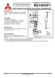
Ton Blokker PA0KLT <strong>PAOKLT</strong> LCD Synthesizer kit <strong>Manual</strong> issue V5.4 for SECOND <strong>ISSUE</strong> <strong>PCB</strong> Jan Verduyn G0BBLFig 4: Circuit Diagram of PA0KLT Synthesizer (Only for 2nd issue <strong>PCB</strong>)www.<strong>SDR</strong>-kits.net 9 of 21
Ton Blokker PA0KLT <strong>PAOKLT</strong> LCD Synthesizer kit <strong>Manual</strong> issue V5.4 for SECOND <strong>ISSUE</strong> <strong>PCB</strong> Jan Verduyn G0BBLFig 5: Interfacing the PA0KLT SynthesizerNotes:1. LCD Display supplied by <strong>SDR</strong>-<strong>Kit</strong>s - backlight connections: Connect pin 16 to pin 1(GND) and Pin 15 via a 47 Ohm resistor to pin 2 (+5V)2. C1 10uF electrolytic is required to stop oscillation on 3.3V supply. C2 is 1uF capacitor inparallel3. Rotary encoder: Viewed from rear with pins facing down: GND = Left, B = Middle and A= Right4. Capacitor colour coding: 1uF 0805 = blue, 1nF 0805 = black, 100nF 0805 = nocolour/no stripe5. Si571 Chip Support is provided fromFirmware version V4.19 onwards. Thisallows FM Modulation of the RF Carrier.Pin 1 (VC) of Si571 should be set to1.65V DC and the Modulating Audioapplied via a Capacitor of 0.1uf - 1uF.1.65V DC can be obtained by soldering a4k7 resistor from pin 1 to GND andanother 4k7 resistor from pin 1 to 3.3Vsupply rail. See figure to the rightSi571 AF modulation Input modificationwww.<strong>SDR</strong>-kits.net 10 of 21
Ton Blokker PA0KLT <strong>PAOKLT</strong> LCD Synthesizer kit <strong>Manual</strong> issue V5.4 for SECOND <strong>ISSUE</strong> <strong>PCB</strong> Jan Verduyn G0BBLBand Select OutputBand Output Frequency MHz0 0000 0.1357 – 0.13781 0001 1.8 – 2.02 0010 3.5 – 4.03 0011 7.0 – 7.34 0100 10.1 – 10.155 0101 14.0 – 14.356 0110 18.068 – 18.1687 0111 21.0 – 21.458 1000 24.89 – 24.999 1001 28.0 – 29.710 1010 50.0 – 54.011 1011 144.0 – 148.012 1100 430.0 – 440.013 1101 0 – 30.0 *14 1110 30.001 – 180.0 *15 1111 180.001 – 800.0 ** = Frequency selected outside AmateurbandTable 2: Band Select Output on AUX Connector J2 pin 1, 2, 3 and 4 (A, B, C, D)Fig 6: LCD Connections and 47 Ohm Resistor soldered to pin 15 with linkto pin 2 (+5V). Pin 16 is linked to pin 1 (GND)www.<strong>SDR</strong>-kits.net 11 of 21
Ton Blokker PA0KLT <strong>PAOKLT</strong> LCD Synthesizer kit <strong>Manual</strong> issue V5.4 for SECOND <strong>ISSUE</strong> <strong>PCB</strong> Jan Verduyn G0BBL5. <strong>Kit</strong> Configuration Options:A number of options are available depending on the type of <strong>Si570</strong> chip orderedand typical applications are shown in fig 7. Reasons for using a transformer are:• Matching the <strong>Si570</strong> CMOS device which has approx 200 Ohm output impedance to a 50Ohm load by using a 4:1 transformer. Up to +12dBm output over 50 Ohms may beobtained this way. Please note the <strong>Si570</strong> CMOS only has one RF output.• <strong>Si570</strong> LVDS and CML devices have two (push-pull) complimentary outputs. Using a 4:1transformer with a centre tap on the primary allows combining the two outputs andmatching into 100 Ohms. An MMIC amplifier (MAV11 or equivalent) will provide 12dBgain...• The secondary of the transformer should be grounded at one end to obtain single endedoutput required when using coax cable to connect to other circuitry.• <strong>Si570</strong> CML device has two (push-pull) complimentary outputs. Each RF output may beinterfaced directly into a 50 Ohm Load or feed a MMIC Amplifier stage (ie MAV11)The following transformers have been used:• homebrew transformer. This consists 5 turns 0.2mm wound trifiliar on a BN43-2402 coreup to 200 MHz. alternatively use a BN61-2402 core with 6 turns 0.2mm trifiliar for up to300 Mhz.• You can also use a Minicircuits T-622 4:1 up to 200 MHz - This drops into the <strong>PCB</strong>.• A Coilcraft WBC4-1WTB 4:1 is supplied with PA0KLT <strong>Kit</strong> C and is specified up to 800MHz and usable up to 945 MHz. This is a SMD transformer which may be soldered directon pads on the 2nd <strong>ISSUE</strong> <strong>PCB</strong> as shown in fig 1. This transfomer may also beconfigured as a 4:1 transformer for <strong>Si570</strong> CMOS chip.www.<strong>SDR</strong>-kits.net 12 of 21
Ton Blokker PA0KLT <strong>PAOKLT</strong> LCD Synthesizer kit <strong>Manual</strong> issue V5.4 for SECOND <strong>ISSUE</strong> <strong>PCB</strong> Jan Verduyn G0BBLFig 7: RF Output configuration options for 2nd Edition <strong>PCB</strong>www.<strong>SDR</strong>-kits.net 13 of 21
Ton Blokker PA0KLT <strong>PAOKLT</strong> LCD Synthesizer kit <strong>Manual</strong> issue V5.4 for SECOND <strong>ISSUE</strong> <strong>PCB</strong> Jan Verduyn G0BBL6. Operating instructions PA0KLT - <strong>Si570</strong> <strong>VFO</strong> v4.0 firmwareFour push Buttons and the Rotary Tuning control are used to operate the <strong>VFO</strong>:These are: Cursor "", Escape ESC , Memory MEM and TUNING (Rotary tuningControl)6.1) There are four modes of Operation: These are:• <strong>VFO</strong> A (<strong>VFO</strong> A frequency - <strong>Manual</strong> tuning - Frequency Recal and Store)• <strong>VFO</strong> B (<strong>VFO</strong> B frequency - <strong>Manual</strong> tuning - Frequency Recal and Store)• Memory A (16 Memory Locations 1 - 16 to Recall or Store Frequencies)• Memory B (16 Memory Locations 1 - 16 to Recall or Store Frequencies)A Short push on "MEM" button switches between these four modes6.2 <strong>VFO</strong> Mode A or <strong>VFO</strong> Mode B• The Tuning speed - Frequency step is adjusted with < and > CURSOR keys. Themininimum frequency step can be set from 1 Hz, 10 Hz, 100 Hz, 1 kHz etc up to 100 Mhz• Press ESC sets all the digits right of the curser to zero• To store the displayed frequency in <strong>VFO</strong> mode to EEPROM, the MEM key is pressed for 2seconds until the LCD displays STORED• Tuning to a frequency and pressing the MEM button for two seconds stores that frequencyready for the next time the unit is switched on. When in <strong>VFO</strong> use, pressing MEM is only tostore the last frequency used in EEPROM. Setting that frequency does not store it in any ofthe 16 Memory locations.6.3 Memory Mode• Use a single quick press of the MEM button selects Memory A or Memory B.• When in Memory A or Memory B mode, press < > cursor buttons to select the requiredmemory location (1 - 16). The previously stored frequency in the selected memory locationis now displayed.• When in the selected Memory location press the ESC button to turn on <strong>Manual</strong> memorytuning and tune to the frequency you want to memorise (store)• When at the desired frequency press the MEM Button for 2 seconds to store that frequency• Press ESC sets all the digits right of the curser to zerowww.<strong>SDR</strong>-kits.net 14 of 21
Ton Blokker PA0KLT <strong>PAOKLT</strong> LCD Synthesizer kit <strong>Manual</strong> issue V5.4 for SECOND <strong>ISSUE</strong> <strong>PCB</strong> Jan Verduyn G0BBL6.4 Synthesizer Configuration Mode for Firmware Versions V4.0 to V4.16The desired frequency and mode is configured as followsPress CURSOR < and > keys together for about 2 seconds until the configuration menuappears.Release and use CURSOR buttons < or > to select Configuration Options 1 to 8 asdescribed below. Store your selection by pressing the MEM keyIntermediate Frequency (IF) Offset Mode:Press MEM and select the desired (MF Offset =IF Offset). The offset can only be apositive frequeny (Local Osc is higher than IF Signal Frequency). Press MEM to store theoffset. Press ESC to cancel.Note 1. If an IF-Offset of less than
Ton Blokker PA0KLT <strong>PAOKLT</strong> LCD Synthesizer kit <strong>Manual</strong> issue V5.4 for SECOND <strong>ISSUE</strong> <strong>PCB</strong> Jan Verduyn G0BBLConfiguring I2C adres <strong>Si570</strong>In V4.13 firmware: This option allows you to select the correct I2C address for AVR tocommunicate with the <strong>Si570</strong> chip. <strong>Si570</strong> chips supplied by <strong>SDR</strong>-<strong>Kit</strong>s from England or byTom Hoflich KM5H have address HEX 55. <strong>Si570</strong> supplied by others may use otheraddresses (for example on German Supplier uses HEX 50). For V4.15 firmware: youmay specify any I2C address between Hex 50 and Hex 5F. The default is Hex 55.END ConfigurationSelection of of this option exits the configuration mode and returns to normal tuning modewith the new saved configuration selected.6.5 Complete Power-up Reset.On rare occassions the EEPROM data may become corrupted which could prevent the <strong>VFO</strong> frominitializing properly. Erasing EEPROM and applying the default Configuration is not possible anda Power-up Reset may be necessary as follows:Press ESC and MEM buttons at same time and apply DC Power until the LCD Screen shows thenormal start-up screen. Release ESC and Mem buttons.Any configuration information previously applied have been lost and need to be re-applied.<strong>PAOKLT</strong> Firmware 4.16 Frequency Range 3.45 MHz – 945 MHzRequired Mode Connection J2 Output Frequency (Offset) RemarksAM 9 to GND 0 Hz (No offset) Calibration done in this modeLSB No connections Displayed Freq – 1.5 kHz DefaultUSB 9 and 15 to GND Displayed Freq + 1.5 kHzCWL 9 and 14 to GND Displayed Freq – 0.75 kHzCWU 14 and 15 GND Displayed Freq + 0.75 kHzLOCK16 to GNDIf IF offset = set to any frequency less than 100 kHz then both IFoffsset and Mode offset are removed regardless what mode isselectedIf IF offset = set to any frequency more than 100 kHz then only ModeOffset is removedTable 3: Connections and Offsets for firmware versions up to V4.166. 6 Synthesizer Configuration Mode for Firmware Version V4.19.www.<strong>SDR</strong>-kits.net 16 of 21
Ton Blokker PA0KLT <strong>PAOKLT</strong> LCD Synthesizer kit <strong>Manual</strong> issue V5.4 for SECOND <strong>ISSUE</strong> <strong>PCB</strong> Jan Verduyn G0BBLThe desired frequency and mode is configured as followsPress CURSOR < and > keys together for about 2 seconds until the configuration menuappears.Release and use CURSOR buttons < or > to select Configuration Option as describedbelow. Store your selection by pressing the MEM keyYou can leave the Configuration mode by pressing ESC. This will reset the AVR whichwill use the options which were stored during Configuration Setup.Intermediate Frequency (IF) Offset Mode:Press MEM and select the desired (MF Offset =IF Offset). The offset can only be apositive frequeny (Local Osc is higher than IF Signal Frequency). Press MEM to store theoffset frequency. Pressing ESC will exit the Configuration mode.Note If the Lock (PTT) is activated by grounding this line to earth then the IF Offsetspecified will be removed.Calibration mode:Press MEM momentarily. The Si57x Crystal frequency is now displayed and may bechanged so the SI57x output frequency measured on a counter is exactly as displayed on theLCD display. The < > Cursor buttons may be used to select the digit to be changed. Oncethe new Crystal frequency has been selected using the Tuning Knob, press the MEM for 2seconds to store the new value. Pressing ESC will abort and exit to the IF Offset Mode.Note: If displayed Frequency is lower than measured frequency then the Crystal frequencyneeds to be lowered and visa versa.Multiplier (<strong>Si570</strong> output frequency = (Displayed Frequency * Multiplier)Presss MEM momentarily and select the required multiplier factor with the cursorbuttons: 2^0 for Multiplier 1, 2^1 for Multiplier 2, 2^2 for Multiplier = 4 and 2^3 forMultiplier = 8. Press MEM for 2 seconds to store. Pressing ESC will abort and exit to theIF Offset Mode.Set Maximum Frequency (280 Mhz for C-grade, 945 for B-grade and 1417 A-grade)The maximum frequency which is supported by the <strong>Kit</strong> depends on the grade of theinstalled <strong>Si570</strong> chip as well as the IF Offset and the Multiplier value selected. Forexample: <strong>Si570</strong>BBB max frequency is 945 MHz. If a IF Offset of 40MHz and Multiplierof 4 is selected then the maximum frequency will be around (940-40)/4 =225 MHz. PressMEM briefly and set maximum frequency using rotary control and buttons. Press MEMfor 2 seconds to store or press ESC to cancel. (Max Freq = 1417 MHz is only supportedfrom V4.19 firmware with Si57x A-grade chips.Minimum frequencyThe minimum frequency which is supported by the Si57x and the firmware is 3.45 MHz butIF Offset and Multiplier need to be taken into account. For Example if IF Offset = 40 MHzand multiplier of 4 is selected then the mimimum frequency should be set to: (3.5+40)/4Configuring I2C adres Si57xwww.<strong>SDR</strong>-kits.net 17 of 21
Ton Blokker PA0KLT <strong>PAOKLT</strong> LCD Synthesizer kit <strong>Manual</strong> issue V5.4 for SECOND <strong>ISSUE</strong> <strong>PCB</strong> Jan Verduyn G0BBLThis option allows you to select the correct I2C address for AVR to communicate with theSi57x chip. Si57x chips supplied by <strong>SDR</strong>-<strong>Kit</strong>s from England or by Tom Hoflich KM5Hhave address HEX 55. Si57x supplied by others may use other addresses (for example onGerman Supplier uses HEX 50). You may specify any I2C address between Hex 50 andHex 5F. The default is Hex 55.<strong>Si570</strong>/<strong>Si570</strong> Selection (default settings Kv = 0 for <strong>Si570</strong>)Selection of of this option allows entering of a value for Kv. If <strong>Si570</strong> is used then Kvshould be set to 0 (default setting). If a Si571 chip is fitted then Kv should be set to astarting value of 180 to ensure that the generated Frequency is as close as possible to thefrequency displayed on the LCD screen AFTER calibration. If errors are seen then try adifferent value (170 or 190) for Kv and after performing calibration. then check whether thefequency error the Si571 has been reduced. After Kv value has been set press MEM tostore the new value or press ESC to quit this option.6.5 Complete Power-up Reset.On rare occassions the EEPROM data may become corrupted which could prevent the <strong>VFO</strong> frominitializing properly. Erasing EEPROM and applying the default Configuration is not possible anda Power-up Reset may be necessary as follows:Press ESC and MEM buttons at same time and apply DC Power until the LCD Screen shows thenormal start-up screen. Release ESC and Mem buttons.Any configuration information previously applied have been lost and need to be re-applied.<strong>PAOKLT</strong> Firmware 4.19 Frequency Range 3.45 MHz - 1417 MHzFeatures since 4.16Support for A Grade chip 3.45 MHz to 1417 MHz without gaps (not warranted)Support for <strong>Si570</strong> and Si571 ChipsAM mode selected as default – Easier CalibrationRequired Mode Connection J2 Output Frequency (Offset) RemarksAM No connection 0 Hz (No offset) Default – calibrationLSB 9 to GND Displayed Freq – 1.5 kHzUSB 9 and 15 to GND Displayed Freq + 1.5 kHzCWL 9 and 14 to GND Displayed Freq – 0.75 kHzCWU 9, 14 and 15 to GND Displayed Freq + 0.75 kHzLOCK16 to GNDAny IF offset and all Mode Offsets are removed regardless whatmode is selectedTable 4: Connections and Offsets for firmware up to V4.19 and higherwww.<strong>SDR</strong>-kits.net 18 of 21
Ton Blokker PA0KLT <strong>PAOKLT</strong> LCD Synthesizer kit <strong>Manual</strong> issue V5.4 for SECOND <strong>ISSUE</strong> <strong>PCB</strong> Jan Verduyn G0BBLSuccess & 73sJan Verduyn G0BBL Jan.Verduyn@gmail.comwww.<strong>SDR</strong>-<strong>Kit</strong>s.net - kit production - English <strong>Manual</strong> - <strong>Kit</strong> support -Ton Blokker PA0KLT Pa0klt@amsat.org<strong>PCB</strong> Design and Firmware developmentwww.<strong>SDR</strong>-kits.net 19 of 21
Ton Blokker PA0KLT <strong>PAOKLT</strong> LCD Synthesizer kit <strong>Manual</strong> issue V5.4 for SECOND <strong>ISSUE</strong> <strong>PCB</strong> Jan Verduyn G0BBLAPPENDIX 1 - Removing clickstop from Rotary encoderNote: The rotary encoder supplied has 24 clickstops, which is enhanced to 96 steps perresolution through firmware by detecting additional steps between each clickstop.Removing of the clickstop is essential for the enhancement to resolution of 96 steps perresolution.( ) Gently bend open the four lugs from (two at each side) of the encoder and removethe rear plate as shown in the picture below.Appendix 1 - Fig 1 - Adjusting Click Stop Springwww.<strong>SDR</strong>-kits.net 20 of 21
Ton Blokker PA0KLT <strong>PAOKLT</strong> LCD Synthesizer kit <strong>Manual</strong> issue V5.4 for SECOND <strong>ISSUE</strong> <strong>PCB</strong> Jan Verduyn G0BBL( ) Remove the contact assembly as shown in the photo below and locate thecontact spring.Gently bend the sliding contract spring away to the back so the pressure on therotary disc is reduced.Ideally you want to maintain a little pressure - You can test by placing thecontract assembly back and trying out until you feel it is right for you.CAUTION: Do not touch or try to adjust the three sliding contacts below as it maydamage the encoder and cause erratic operation.( ) After adjustment fit the rear plate and secure by bending the lugs back in originalpositionAppendix 1 - Fig 2 - Adjusting Click Stop SpringEnd of Appendix 1.www.<strong>SDR</strong>-kits.net 21 of 21