DG8SAQ VNWA Kit Assembly Manual - SDR-Kits
DG8SAQ VNWA Kit Assembly Manual - SDR-Kits
DG8SAQ VNWA Kit Assembly Manual - SDR-Kits
- No tags were found...

You also want an ePaper? Increase the reach of your titles
YUMPU automatically turns print PDFs into web optimized ePapers that Google loves.
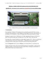
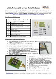
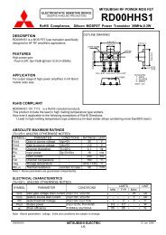
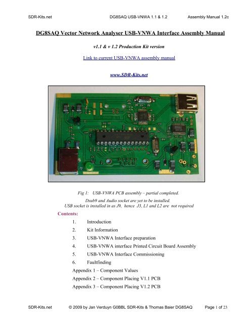
<strong>SDR</strong>-<strong>Kit</strong>s.net <strong>DG8SAQ</strong> USB-<strong>VNWA</strong> 1.1 & 1.2 <strong>Assembly</strong> <strong>Manual</strong> 1.2c<strong>DG8SAQ</strong> Vector Network Analyser USB-<strong>VNWA</strong> Interface <strong>Assembly</strong> <strong>Manual</strong>v1.1 & v 1.2 Production <strong>Kit</strong> versionLink to current USB-<strong>VNWA</strong> assembly manualwww.<strong>SDR</strong>-<strong>Kit</strong>s.netFig 1:USB-<strong>VNWA</strong> PCB assembly – partial completed.Dsub9 and Audio socket are yet to be installed.USB socket is installed in as J9, hence J3, L1 and L2 are not requiredContents:1. Introduction2. <strong>Kit</strong> Information3. USB-<strong>VNWA</strong> Interface preparation4. USB-<strong>VNWA</strong> interface Printed Circuit Board <strong>Assembly</strong>5. USB-<strong>VNWA</strong> Interface Commissioning6. FaultfindingAppendix 1 – Component ValuesAppendix 2 – Component Placing V1.1 PCBAppendix 3 – Component Placing V1.2 PCB<strong>SDR</strong>-<strong>Kit</strong>s.net © 2009 by Jan Verduyn G0BBL <strong>SDR</strong>-<strong>Kit</strong>s & Thomas Baier <strong>DG8SAQ</strong> Page 1 of 23
<strong>SDR</strong>-<strong>Kit</strong>s.net <strong>DG8SAQ</strong> USB-<strong>VNWA</strong> 1.1 & 1.2 <strong>Assembly</strong> <strong>Manual</strong> 1.2c3.3 Printed Circuit Board Preparation[ ] Check whether your kit contains version contains USB-<strong>VNWA</strong> v1.1 or v1.2 PCB If yourversion is different check whether you have the correct USB-<strong>VNWA</strong> assembly manual applicableto your particular PCB version supplied.Appendix 2 has V1.1 component placing whilst Appendix 3 has the V1.2 PCB component layout.<strong>SDR</strong>-<strong>Kit</strong>s.net © 2009 by Jan Verduyn G0BBL <strong>SDR</strong>-<strong>Kit</strong>s & Thomas Baier <strong>DG8SAQ</strong> Page 5 of 23
<strong>SDR</strong>-<strong>Kit</strong>s.net <strong>DG8SAQ</strong> USB-<strong>VNWA</strong> 1.1 & 1.2 <strong>Assembly</strong> <strong>Manual</strong> 1.2cC12, C15, C16, C17, C24,C25, C26, C29, C32, C33,C34, C37, C38[ ] Install capacitors (1nF 0603 black) C5, C31, C35[ ] Install capacitors (27pF 0603 red/green) C3, C7, C27[ ] Install capacitors (15pF 0603 red/black) C28[ ] Caution: Observe orientation as shown in Appendix 2 or 3 (black stripe or +symbol) in the following 2 step. (For Tantalum capacitors supplied in the <strong>Kit</strong> theBLACK STRIPE indicates the + terminal.)[ ] Install capacitors (10uF) C1, C9, C11, C13, C14,C18, C19[ ] Install diodes (MBR020L marking 1B28 or B25) D2, D3Caution: Observe orientation of black stripe shown in Appendix 2 or the letter “c” inAppendix 3. Use a 5x magnifier to detect the small raised edge at one end of the caseof the diode, which indicates the cathode.[ ] Install LE33 U1, U3[ ] Install IRLML6401 Q1 (mark F8?85)[ ] LED D1 (Connect the Anode (Longer leadto the square pad)[ ] Crystals X1 (6 MHz) X2 (12 MHz)[ ] Fuse XF010 or PFRA010 F1Note:In the following steps the USB-B connector is installed in position J9 to suit the<strong>SDR</strong>-<strong>Kit</strong>s <strong>VNWA</strong> Enclosure which has USB connection at the rear. If you require theUSB-B connection on the front panel (not recommended) then install the USB-Bsocket provided in position J3 instead of in position J9.[ ] Install USB-B Connector J9[ ] Install USB-A Connector (optional connector)[ ] Choke Inductor 4.7 uH L3, L4 when J9 installedAlternatively as L1, L2 when J3 installed<strong>SDR</strong>-<strong>Kit</strong>s.net © 2009 by Jan Verduyn G0BBL <strong>SDR</strong>-<strong>Kit</strong>s & Thomas Baier <strong>DG8SAQ</strong> Page 7 of 23
<strong>SDR</strong>-<strong>Kit</strong>s.net <strong>DG8SAQ</strong> USB-<strong>VNWA</strong> 1.1 & 1.2 <strong>Assembly</strong> <strong>Manual</strong> 1.2c• Select “No, not this time”• Press “NEXT”The following screen should now be displayed:Deselect “Install the software automatically”<strong>SDR</strong>-<strong>Kit</strong>s.net © 2009 by Jan Verduyn G0BBL <strong>SDR</strong>-<strong>Kit</strong>s & Thomas Baier <strong>DG8SAQ</strong> Page 11 of 23
<strong>SDR</strong>-<strong>Kit</strong>s.net <strong>DG8SAQ</strong> USB-<strong>VNWA</strong> 1.1 & 1.2 <strong>Assembly</strong> <strong>Manual</strong> 1.2cSelect “install from a list or specific location”Press “Next>”The following screen is displayed• Deselect “Search removable Media”• Select “Include this location in the search”• Press “Browse”• Select Folder AVR-USB-Driver• Click “Ok”• Press “Next>”• Software is being installed<strong>SDR</strong>-<strong>Kit</strong>s.net © 2009 by Jan Verduyn G0BBL <strong>SDR</strong>-<strong>Kit</strong>s & Thomas Baier <strong>DG8SAQ</strong> Page 12 of 23
<strong>SDR</strong>-<strong>Kit</strong>s.net <strong>DG8SAQ</strong> USB-<strong>VNWA</strong> 1.1 & 1.2 <strong>Assembly</strong> <strong>Manual</strong> 1.2cWhen successfully installed, following message displayed:Once <strong>DG8SAQ</strong> Driver installation is installed three messages may be displayed and/or threeaudible are sounded whenever the USB-<strong>VNWA</strong> is connected to the PC:• USB-Codec detected PCM2900<strong>SDR</strong>-<strong>Kit</strong>s.net © 2009 by Jan Verduyn G0BBL <strong>SDR</strong>-<strong>Kit</strong>s & Thomas Baier <strong>DG8SAQ</strong> Page 13 of 23
<strong>SDR</strong>-<strong>Kit</strong>s.net <strong>DG8SAQ</strong> USB-<strong>VNWA</strong> 1.1 & 1.2 <strong>Assembly</strong> <strong>Manual</strong> 1.2c• USB Human Interface detected TUSB2036 chip• USB-Controller detected ATMEGA88Note: Windows Vista Driver Installation:Procedure how to download the <strong>DG8SAQ</strong> Driver for Windows Vista will be providedin the following link: http://sdr-kits.net/<strong>VNWA</strong>/USB-<strong>VNWA</strong>/AVR-USB-Driver.zip5.2 USB-<strong>VNWA</strong> Application Installation[ ] Download and unpack the USB-<strong>VNWA</strong> Software in a new separate directory from:http://sdr-kits.net/<strong>DG8SAQ</strong>/<strong>VNWA</strong>/<strong>VNWA</strong>_USB_Application.zipNote:The above link is to the current tested USB-<strong>VNWA</strong> application available for generalrelease. Experimental USB_<strong>VNWA</strong> releases may be made available in which casefollow the specific link provided.fig 3: USB_<strong>VNWA</strong> Application files after downloading[ ] Run USB-<strong>VNWA</strong> Software by clicking on <strong>VNWA</strong> Application icon.[ ] Select “Options” and “Setup” and “Interface Type” and click “USB Mode” The followingscreen in fig 4 should be displayed<strong>SDR</strong>-<strong>Kit</strong>s.net © 2009 by Jan Verduyn G0BBL <strong>SDR</strong>-<strong>Kit</strong>s & Thomas Baier <strong>DG8SAQ</strong> Page 14 of 23
<strong>SDR</strong>-<strong>Kit</strong>s.net <strong>DG8SAQ</strong> USB-<strong>VNWA</strong> 1.1 & 1.2 <strong>Assembly</strong> <strong>Manual</strong> 1.2c[ ] Next select “USB Setting”fig 4: USB Mode Selected[ ] Press “Rescan USB Bus” and check whether the USB bus drivers are detected as shown infig 3. “<strong>DG8SAQ</strong> <strong>VNWA</strong> USB Controller found”[ ] Enter the License code provided with your kit in the field shown in fig 5.Note the 2 colons, the first colon is between the family name and the licensing Date. Thesecond colon terminates the License code. Example: Jan.Verduyn:2009.05.01:[ ] Close (Exit) down the <strong>DG8SAQ</strong> <strong>VNWA</strong> application. This stores the licence code..<strong>SDR</strong>-<strong>Kit</strong>s.net © 2009 by Jan Verduyn G0BBL <strong>SDR</strong>-<strong>Kit</strong>s & Thomas Baier <strong>DG8SAQ</strong> Page 15 of 23
<strong>SDR</strong>-<strong>Kit</strong>s.net <strong>DG8SAQ</strong> USB-<strong>VNWA</strong> 1.1 & 1.2 <strong>Assembly</strong> <strong>Manual</strong> 1.2cfig 5: Entering License Key – after Rescan USB Bus[ ] Start up the <strong>DG8SAQ</strong> USB-<strong>VNWA</strong> application once more to allow the license code isrecognized.[] Select “Options” and “Setup” and “Interface Type” and click Test USB Interface.This test should be succesfully completed, if the licence key was correctly stored.[ ] Now select “USB Settings” and verify whether “USB Audio Codec” has been selectedSelect “Reference = Left Channel” – otherwise sync will NOT be detectedFig 6: USB Setup Screen[ ] Next select “Audio Settings” and press on “TestAudio “ and select “Reflect”With <strong>VNWA</strong> TX Port not terminated typical Audio Levels as shown in fig 7 should bedisplayed.[ ] If Audio Reference is not visible, check whether the <strong>VNWA</strong> and USB-<strong>VNWA</strong> audio socketsare connected via a stereo 3.5mm to 3.5mm cable.<strong>SDR</strong>-<strong>Kit</strong>s.net © 2009 by Jan Verduyn G0BBL <strong>SDR</strong>-<strong>Kit</strong>s & Thomas Baier <strong>DG8SAQ</strong> Page 16 of 23
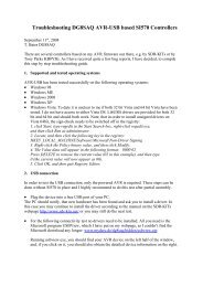
<strong>SDR</strong>-<strong>Kit</strong>s.net <strong>DG8SAQ</strong> USB-<strong>VNWA</strong> 1.1 & 1.2 <strong>Assembly</strong> <strong>Manual</strong> 1.2cFinal <strong>Assembly</strong>Fig 7: Audio Settings ScreenOnce the USB-controlled <strong>VNWA</strong> has been fully tested, the USB_<strong>VNWA</strong> Interface PCB isfitted in the Enclosure.Two connections cables are required to connect USB-<strong>VNWA</strong> PCB to the <strong>VNWA</strong> PCB after fittingin the enclosure.Cable 1:Dsub connection cable[ ] A short cable needs to be made up consisting of the D9 IDC Male connector to the D9 IDCFemale connector. The length of the cable is 5cm. Fig 6 shows typical assembly for the<strong>SDR</strong>-<strong>Kit</strong>s ready drilled enclosure where VNA and USB-<strong>VNWA</strong> Interface PCBs are mountedwith the copper sides facing at a distance of 8.1mm.[ ] Reduce the 10 core flat cable provided to 9 cores using scissors.[ ] Identify the “stripe” denoting pin 1 on top left corner of the D9sub Male connector. whenlooking at the pins. Position the flat cable in this connector so the blue core is on the side(pin1) (see fig 6).[ ] Place connector in a Vice and whilst holding connector cable squarely aligned, press the clamponto the male connector by operating the Vice, until the rear clamp clicks in place.<strong>SDR</strong>-<strong>Kit</strong>s.net © 2009 by Jan Verduyn G0BBL <strong>SDR</strong>-<strong>Kit</strong>s & Thomas Baier <strong>DG8SAQ</strong> Page 17 of 23
<strong>SDR</strong>-<strong>Kit</strong>s.net <strong>DG8SAQ</strong> USB-<strong>VNWA</strong> 1.1 & 1.2 <strong>Assembly</strong> <strong>Manual</strong> 1.2c[ ] Identify pin 1 (top right corner) of the D9 Female connector when looking at the front holes.Position the flat cable in this connector so the blue core is on the side (pin1) (see fig 6)[ ] Place connector in a Vice and whilst holding connector cable squarely aligned, press the clamponto the female connector by operating the Vice until you hear the clamp clicks in place.Fig 6. D9sub IDC Connection cable assembled to suit<strong>SDR</strong>-<strong>Kit</strong>s ready drilled Enclosure. Distance between connectors is 25 - 30mmCable 2:Stereo audio cable – with 3.5mm stereo plugs at either end[ ] Cut 2 length of 7cm wire (not provided) and solder between the two stereo plugsprovided. Check with an ohm meter. Perfectionists may use screened cable however thisthis is not necessary. This short cable plugs into audio sockets of the two PCBs.Only after the USB-controlled <strong>VNWA</strong> has been fully tested, the USB_<strong>VNWA</strong> Interface PCB isfitted in the Enclosure.Instructions to be provided in the next version of the <strong>VNWA</strong> <strong>Assembly</strong> <strong>Manual</strong>Note it is recommended that the Printed Circuit board is directly soldered in thehorizontal zintec coated metal chassis. Use a 40W or 50W Soldering iron with a big<strong>SDR</strong>-<strong>Kit</strong>s.net © 2009 by Jan Verduyn G0BBL <strong>SDR</strong>-<strong>Kit</strong>s & Thomas Baier <strong>DG8SAQ</strong> Page 18 of 23
<strong>SDR</strong>-<strong>Kit</strong>s.net <strong>DG8SAQ</strong> USB-<strong>VNWA</strong> 1.1 & 1.2 <strong>Assembly</strong> <strong>Manual</strong> 1.2ctip and first remove the blue/grey zintec coating with a small wirebrush or a smallhobby knife.This completes USB_<strong>VNWA</strong> <strong>Kit</strong> assembly6. USB-<strong>VNWA</strong> FaultfindingPlease consult the <strong>DG8SAQ</strong> USB-<strong>VNWA</strong> Helpfile.• USB Not recognized - Is <strong>DG8SAQ</strong> Driver properly installed?USB Enumeration consists of 3 stages: a) detection of USB Hub, b) detection of Atmega88Controller, and c) detection of PCM2900 Audio Codec.Please consult the <strong>DG8SAQ</strong> USB-<strong>VNWA</strong> Helpfile. “USB Troubleshooting Guide”• Are 12 MHz or 6 MHz Crystals Oscillating? Check with Scope with x10 Probe• Audio sockets connected with 3.5mm audio stereo cable?• Is the Soundcard in use by another application? CDROM etc• Is another USB device using the <strong>DG8SAQ</strong> driver connected to the Personal Computer ? (forexample Softrock Radio with QRP2000 Synthesizer)<strong>SDR</strong>-<strong>Kit</strong>s.net © 2009 by Jan Verduyn G0BBL <strong>SDR</strong>-<strong>Kit</strong>s & Thomas Baier <strong>DG8SAQ</strong> Page 19 of 23
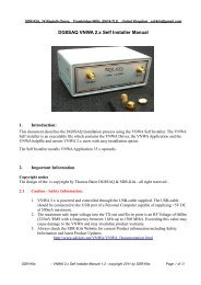
<strong>SDR</strong>-<strong>Kit</strong>s.net <strong>DG8SAQ</strong> USB-<strong>VNWA</strong> 1.1 & 1.2 <strong>Assembly</strong> <strong>Manual</strong> 1.2cAPPENDIX 1 – USB-<strong>VNWA</strong> Interface - Component ValuesC16 100n J26 3pins R18 22RC17 100n L1 400mA choke R19 1K5C18 10u L2 400mA choke R20 1MC19 10u L3 400mA choke R21 68RC20 1u L4 400mA choke R22 68RC21 1u Q1 IRLML6401 R23 10kC22 1u I1 28 p socket R26 1K5C23 1u R27 10KC24 100n U1 LE33 R28 0RC25 100n U2 TUSB2036 R29 100RC26 100n U3 LE33 R30 100RC27 27p U4 PCM2900 R31 100RC28 15p X1 6 MHz Crystal R32 100RC29 100n X2 12 MHz Crystal R33 100RC31 1n R34 1kC32 100n R35 22RC33 100n R36 22RC34 100n R37 10kC35 1n R38 680RC36 1u R39 47RC37 100n R40 680RC38 100n R41 0RR42 omitAPPENDIX 2 – USB-<strong>VNWA</strong> Component Placing V1.1 PCB<strong>SDR</strong>-<strong>Kit</strong>s.net © 2009 by Jan Verduyn G0BBL <strong>SDR</strong>-<strong>Kit</strong>s & Thomas Baier <strong>DG8SAQ</strong> Page 20 of 23
<strong>SDR</strong>-<strong>Kit</strong>s.net <strong>DG8SAQ</strong> USB-<strong>VNWA</strong> 1.1 & 1.2 <strong>Assembly</strong> <strong>Manual</strong> 1.2c<strong>SDR</strong>-<strong>Kit</strong>s.net © 2009 by Jan Verduyn G0BBL <strong>SDR</strong>-<strong>Kit</strong>s & Thomas Baier <strong>DG8SAQ</strong> Page 21 of 23
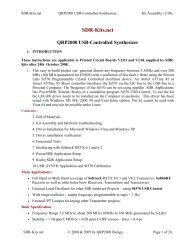
<strong>SDR</strong>-<strong>Kit</strong>s.net <strong>DG8SAQ</strong> USB-<strong>VNWA</strong> 1.1 & 1.2 <strong>Assembly</strong> <strong>Manual</strong> 1.2cAppendix 3 – USB-<strong>VNWA</strong> Component Placing V1.2 Component placing(c = D2 and D3 cathode - + = black strip on Tantalum Capacitor<strong>SDR</strong>-<strong>Kit</strong>s.net © 2009 by Jan Verduyn G0BBL <strong>SDR</strong>-<strong>Kit</strong>s & Thomas Baier <strong>DG8SAQ</strong> Page 22 of 23
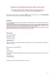
<strong>SDR</strong>-<strong>Kit</strong>s.net <strong>DG8SAQ</strong> USB-<strong>VNWA</strong> 1.1 & 1.2 <strong>Assembly</strong> <strong>Manual</strong> 1.2cAPPENDIX 4<strong>DG8SAQ</strong> USB-<strong>VNWA</strong> 1.1 & 1.2 Circuit DiagramsThis Appendix is supplied to <strong>Kit</strong> builders with the <strong>Kit</strong> parts who haveagreed with the <strong>SDR</strong>-<strong>Kit</strong> Terms and Conditions<strong>SDR</strong>-<strong>Kit</strong>s.net © 2009 by Jan Verduyn G0BBL <strong>SDR</strong>-<strong>Kit</strong>s & Thomas Baier <strong>DG8SAQ</strong> Page 23 of 23